Corken 91 Installation, Operation & Maintenance Manual
Hide thumbs
Also See for 91:
- Installation, operation & maintenance manual (96 pages) ,
- Installation, operation & maintenance manual (100 pages)
Table of Contents
Advertisement
ORIGINAL INSTRUCTIONS
Installation, Operation
& Maintenance Manual
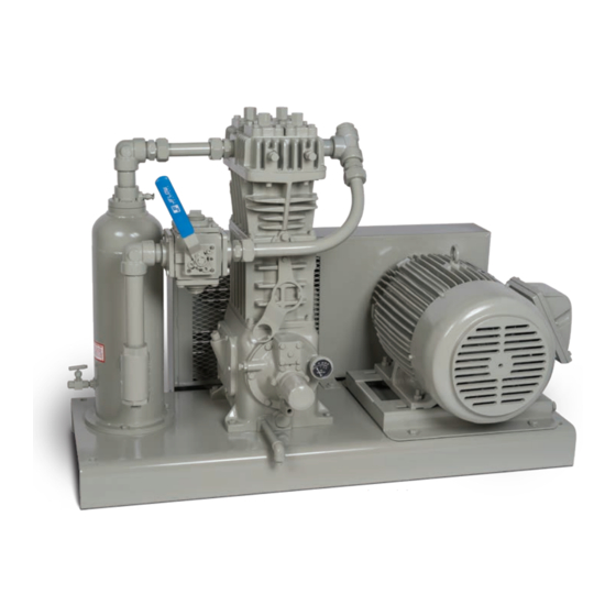
D- and T-Style Model 91 Compressors
Model T91 Compressor
with 103 Mounting
Warning: (1) Periodic inspection and maintenance of Corken products is essential. (2) Inspection, maintenance and installation of
Corken products must be made only by experienced, trained and qualified personnel. (3) Maintenance, use and installation of Corken
products must comply with Corken instructions, applicable laws and safety standards. (4) Transfer of toxic, dangerous, flammable or
explosive substances using Corken products is at user's risk and equipment should be operated only by qualified personnel according
to applicable laws and safety standards.
Solutions beyond products...
Bare D91 Compressor
IE107A
Advertisement
Table of Contents

Subscribe to Our Youtube Channel
Related Manuals for Corken 91


Summary of Contents for Corken 91
- Page 1 Warning: (1) Periodic inspection and maintenance of Corken products is essential. (2) Inspection, maintenance and installation of Corken products must be made only by experienced, trained and qualified personnel. (3) Maintenance, use and installation of Corken products must comply with Corken instructions, applicable laws and safety standards. (4) Transfer of toxic, dangerous, flammable or explosive substances using Corken products is at user’s risk and equipment should be operated only by qualified personnel according...
- Page 2 Corken One Year Warranty CORKEN, INC. warrants that its products will be free from defects in material and workmanship for a period of one year from date of installation, provided that the warranty shall not extend beyond twenty-four (24) months from the date of shipment from CORKEN.
-
Page 3: Table Of Contents
Table of Contents Chapter 1—Introduction . . . . . . . . . . . . . . . . . . . . . . . . . . . . . . . . . . . . . . . . . . . . . . . . . . . . . . . . . . . . . . . . . . . . . . . . 4 1.1 Construction Features . -
Page 4: Chapter 1-Introduction
Pressure-lubricated crankcase with filter: Self-reversing oil pump ensures proper lubrication regardless of directional rotation to main and connecting rod bearings. Standard 10-micron filter ensures long-lasting bearing life (not available on Model 91). Registered trademark of TTI Group Ltd. Construction Details—Model FT91 Compressor... -
Page 5: Construction Features
Cutaway of is a vertical single-stage, single-acting reciprocating crosshead guide compressor designed to handle flammable gases like LPG and toxic gases such as ammonia. Corken compressors can handle these potentially dangerous Cutaway of gases because the LPG/NH is confined in the... -
Page 6: Running Gear
(compressor, baseplate, motor, etc.). For a model 91, the baseplate should be secured to the foundation using 1/2" diameter x 12" long “J” bolts. NOTE: Always use all anchor holes . -
Page 7: Liquid Traps
To prevent the entry of liquid into the compressor, a liquid Concrete trap is always used on liquefied gas applications. Corken Ground level foundation offers three liquid trap options for removing liquids in the gas stream (see figure 2.4A). -
Page 8: Driver And Flywheel
— can draw This design is standard on Corken's 109A and 107A moist air into the motor. The moist air will condense compressor mountings. -
Page 9: Oils To Avoid
Corken compressors. The minimum Viscosity Index critical nature of the services where these compressors for oils used in Corken compressors is 95 (VI is a are used, selecting the appropriate high quality oil is unit-less number). This is particularly important when the most economical choice. -
Page 10: Crankcase Oil Recommendations
• Remove and drain the oil filter or replace with a new from a lubrication standpoint. Never use a detergent one (part number 4225). NOTE: The Corken model 91 oil in a compressor in ammonia service. Ammonia will compressor does not use an oil filter. -
Page 11: Oil Change Intervals
-58°F (-50°C) Royal Purple Uni-Temp 68 -51°F (-46°C) Consult Corken for oil recommendations in very hot climates—ambient temperatures consistently above 100°F (38°C). Oil type: C=Conventional, S=Synthetic, B=Conventional/Synthetic blend Information available from oil manufacturers at the time of publication. Mobil SHC oils are synthetic oils which require that the crankcase be flushed of residual mineral oil. -
Page 12: Crankcase Oil Recommendations (Synthetic Food Grade Oils)
CompressorGuard 68 NOTES: Consult Corken for Oil Recommendations in very hot climates—ambient temperatures consistently above 100ºF (38ºC) Information stated by oil manufacturers at the time of publication. See oil manufacturer's product data sheets for additional details. 2 .6 .9 Oil Analysis 2 .6 . -
Page 13: Relief Valves
The set point should follow these guidelines: An relief valve must be installed at the compressor discharge. On Corken's 107-style mountings, a relief valve • Less than the compressor’s maximum working should be fitted in the piping between the compressor pressure. -
Page 14: Chapter 3-Start Up
How To Align the Sheave to the Flywheel on starting the compressor! Failure to do so may result Corken's YouTube channel. in a costly (or dangerous) mistake . The flywheel is mounted on the shaft via a split, tapered Before Starting the Compressor bushing and three bolts (refer to figure 3.2A). -
Page 15: Chapter 4-Routine Maintenance Chart
5. Check all mounting shims, cylinder and piping 18. Verify that all valves are open or closed as required. supports to ensure that no undue twisting forces exist 19. Double-check all of the above. on the compressor. After Starting Compressor 6. -
Page 16: Chapter 5-Routine Service And Repair Procedures
Chapter 5—Routine Service and Valve Holddown Assemblies: Depending on the model of compressor, the valve holddown assembly has all or a Repair Procedures combination of the following (Spec 9 shown below): CAUTION: Always relieve pressure in the unit Unloader cap before attempting any repairs . -
Page 17: Heads
NOTE: The spec 3 suction valves for a model 91 are pre-set so no adjustments to the liquid relief pressure are necessary. 3. Replace the holddown screw and tighten to the torque value listed in Appendix B. -
Page 18: Pistons
Figure 5.5A: Packing adjusting nuts. Piston Rod 5 .6 Cylinder and Packing Figure 5.4A: Piston cross section model sizes 91 through 491 7. Reinstall the piston platform with the same thickness If the compressor is properly maintained, the cylinder of shims as before, BUT DO NOT REINSTALL THE is rarely replaced. -
Page 19: Model D91 (D-Style) Compressor
. Push in each one completely before adding the next ring . Corken's compressor is a precision piece of equipment with very close tolerances so treat it with care and never 1. Start at the bottom of the packing cartridge and insert force parts in or out. -
Page 20: Model T91 (T-Style) Compressor
Upper packing set (Spec A or B): 8. Retainer ring Female NOTE: Make sure the new packing set is in the 7. Washer packing proper orientation . Refer to the parts details listed ring in Appendix E while following the instructions below . Install the male, V-ring, and female packing one at a 6. - Page 21 3. Locate the cartridge holddown screw on top of the 1. Retainer ring crosshead guide and packing barrel. Remove the Male packing cartridge holddown screw, spacer, and O-ring. ring 2. Washer 4. Reach through the opening behind the inspection/ 3. Spring nameplate on the side of the crosshead guide with a V-ring up screw driver and lightly pry up on the adjusting screw...
- Page 22 Spec H only: Spec F only: 1. Before inserting the packing assembly, insert the oil 1. Starting at the top of the packing cartridge, insert all wiper ring through the top of the packing cartridge and parts in the following order: lay loose until it is time to slide the packing cartridge 7.
-
Page 23: Bearing Replacement For Crankcase And Connecting Rod
5 . 7 Bearing Replacement for the holes do not align, press out and insert a new one. Bore the wrist pin bushing I.D. as indicated Crankcase and Connecting Rod in Appendix E. See parts details for connecting rod assembly. Over boring the bushing can lead to Before starting these instructions, refer the parts details premature failure of the wrist pin bushing. -
Page 24: Replacing Crankcase Roller Bearings
If corrosion or pitting is Following a few simple procedures greatly minimize the present, the roller bearings should be replaced. When risk of corrosion and damage. Corken recommends replacing roller bearings, always replace the entire the following: bearing, not just the cup or the cone. -
Page 25: Model Number Identification Code And Available Options
Appendix A—Model Number Identification Code and Available Options D91 Single-stage with NPT and FD91 ASME Class 300 RF Flanged Connections (D-Style) Model Number FD91 Base Model Number D91 (NPT) Base X X X X X X X X X X (ASME Class 300 RF Flange) Double Inlet... - Page 26 Appendix A—Model Number Identification Code and Available Options T91 Single-stage with NPT and FT91 ASME Class 300 RF Flanged Connections (T-Style) Model Number FT91 Base Model Number T91 (NPT) Base X X X X X X X X X X (ASME Class 300 RF Flange) Triple Inlet...
-
Page 27: Specifications
Appendix B—Specifications for All Models 91 Applications Equipment Type and Options Single-acting, vertical, reciprocating piston type vapor compressor Bulk transfer Tank evacuation Single packed rod Vapor recovery Gas scavenging NPT or Class 300 RF connections Features and Benefits Self-lubricating piston rings:... - Page 28 Appendix B—Specifications for All Models 91 Material Specifications Part Standard Material Head, Cylinder Ductile iron ASTM A536 Crosshead guide crankcase, flywheel, bearing carrier Gray iron ASTM A48, Class 30 Flange Ductile iron ASTM A536 Valve seat and bumper 17-4 PH stainless steel...
- Page 29 Appendix B—Specifications for All Models 91 Clearances and Dimensions for Single-Acting Models 0.020 “X” piston clearance figure 5.4A and 5.4B 0.044 0.001 Clearance from connecting rod bearing to crankshaft journal 0.0025 0.0006 Clearance from wrist pin to wrist pin bushing 0.0011...
-
Page 30: Compressor Selection
Appendix C—Compressor Selection 103 Mounting Compressor Mounting Selections Discharge pressure gauge Suction 103 Mounting pressure gauge • Steel baseplate Enclosed steel beltguard • V-belt drive Optional motor • Adjustable driver slide base • Enclosed steel beltguard • Suction and discharge pressure gauges Standard 107 Items •... -
Page 31: Outline Dimensions
Appendix D—Outline Dimensions Model D91 All dimensions are in inches (millimeters). - Page 32 Appendix D—Outline Dimensions Model FD91 All dimensions are in inches (millimeters).
- Page 33 Appendix D—Outline Dimensions Model T91 All dimensions are in inches (millimeters).
- Page 34 Appendix D—Outline Dimensions Model FT91 All dimensions are in inches (millimeters).
- Page 35 This page is intentionally blank.
-
Page 36: Parts Details
Appendix E—Parts Details for 91 and F91 Head and Valve Assembly D91 and T91 Head Assembly Valve Holddown Assemblies Suction Suction Suction Discharge Spec. 3 Spec. 4 Spec. 9 All Specs. FD91 and FT91 Head Assembly Valve Assemblies Suction Valve Spec. - Page 37 Appendix E—Parts Details for 91 and F91 Head and Valve Assembly Head and Valve Bill of Materials Part No . Description Qty . Part No . Description Qty . No . No . 2374 Head (model 91) Discharge valve plate...
- Page 38 Appendix E—Parts Details for 91 and F91 Equalization Tube Assembly Model 91 Tube Assembly—Bill of Materials Standard Non Coated Compressor Part No . Description Qty . No . 2388-1 Tube elbow (3/4T x 1/2P) Tube (3/4 x 0.035 304 3434-1...
- Page 39 Appendix E—Parts Details for 91 and F91 Head and Valve Assembly Piston—Bill of Materials Piston Diameter 3" (7 .62 cm) Part No . Description Qty . No . 7002-010TP100A Screw (socket head) 7207-010A Lock washer 1983 Head (iron) 1983C Head, coated (iron)
- Page 40 Appendix E—Parts Details for 91 and F91 D-Style Packing Assembly Packing Set Orientation Spec A Spec B (V-ring up) (V-ring down) Retainer ring grooves Cutaway of packing cartridge V-ring CAUTION: Always relieve pressure in the unit before attempting any repairs.
- Page 41 Appendix E—Parts Details for 91 and F91 D-Style Packing Assembly Spec. A Spec. B Material Code Buna-N V-ring Neoprene ®c down Viton ®c Packing—Bill of Materials PTFE Part No . Description Qty . No . 4940 Crosshead guide 4940-X Crosshead guide assembly...
- Page 42 Appendix E—Parts Details for 91 and F91 T-Style Packing Assembly Packing Set Orientation Spec G Spec F or H (V-ring up) (V-ring down) Retainer ring grooves Cutaway of packing cartridge Material Code Buna-N Neoprene ®c Viton ®c Packing—Bill of Materials PTFE Part No .
- Page 43 Appendix E—Parts Details for 91 and F91 T-Style Packing Assembly Spec. F & G Spec. H Retainer ring grooves V-ring down V-ring Spec. G & H Spec. F V-ring down V-ring CAUTION: Always relieve pressure in the unit before attempting any repairs.
- Page 44 Appendix E—Parts Details for 91 and F91 Connecting Rod Assembly Connecting Rod—Bill of Materials Qty . per Part No . Description No . Compressor Crosshead assembly 1132-X3 (D-Style) Crosshead assembly 1132-X7 (T-Style) 1498 Retainer ring 2505 Wrist pin 1846-X Wrist pin bushing...
- Page 45 Appendix E—Parts Details for 91 and F91 Flywheel Assembly Compressor shaft Flywheel—Bill of Materials Back Side Part No . Description Qty . No . 3271 Flywheel (14" O.D., 2 groove) Hub with three bolts and H SF-1.125 lockwashers Assembly Assembly Name...
- Page 46 Appendix E—Parts Details for 91 and F91 Crankcase Assembly...
- Page 47 Appendix E—Parts Details for 91 and F91 Crankcase Assembly Packing—Bill of Materials Part No . Description Qty . No . 3259 Oil seal 1450 Groove pin (1/8" x 1") Hex head (3/8"–16 x 3/4", 7001-037NC075A grade 5) 3260 Bearing carrier...
-
Page 48: Compressor Foundation Design Considerations
85 dBa at three feet. size necessitates the same type of mounting as the other large compressors. Noise testing is not available from the Corken factory. It would not be a reliable indicator of noise generated in the 3. Horizontal Compressors: Corken’s horizontal field once all the variables are established. - Page 49 Sometimes they work and other times they do not. Vibration isolating Small Corken vertical compressors (models 91, 151, 191, springs generally do not work and can actually magnify 291, 351, 391 and 491) do fine with the baseplate mounted the problem.
- Page 50 Specifications for Baseplate and Skid Mountings Formed Steel Baseplate Specifications 1. Baseplate thickness should be at least 3/8 inches (1 cm). 2. Maximum height of baseplate is 4 inches (10 cm). 3. Maximum width should not exceed 26 inches (66 cm). 4.
- Page 51 Structural Steel Skid Specifications 1. You may use top plates as needed; however, the compressor must be placed directly over the main beams. See illustrations 10, 11, and 12 on the following pages. 2. Forklift slots are acceptable. 3. Acceptable types of construction are C-section beams, I-beams or wide-flange I-beams. a.
- Page 52 Illustration 1 Foundation—Ground Level Your concrete foundation should be 8 to 10 inches deep and larger than the compressor baseplate. Length and width should be 4 inches longer and wider. Proper depth is necessary for adequate bolting and stability. The foundation should also be Baseplate should be Concrete foundation a maximum of 4"...
- Page 53 Grouting the baseplate to a maximum of 4" high the concrete foundation is highly recommended small Concrete compressors (91, 151, 191, 291, 351, foundation Ground level 391, and 491) and is required for the large compressors (591, 691, 791, 891, and HG600).
- Page 54 Illustration 7 Mounting Baseplate—Concrete and Rubber Mounts Rubber mounts pads have Baseplate should not be suspended mixed results and generally are not recommended. At times they can magnify the vibration. The baseplate should not be suspended in the air . Baseplate should be a maximum of 4"...
- Page 55 Fixed mounting at the compressor’s point center of gravity Installing mounts at the compressor’s center of gravity is effective on smaller compressors (models 91, 151, 191, 291, 351, 391, and 491). Suspended mounting Illustration 10 Mounting Baseplate—Concrete and Steel Mounting Base...
- Page 56 Illustration 12 Mounting Baseplate—Concrete and Steel Mounting Base Cross beams and main beams should be mounted ush to Mount the compressor baseplate concrete foundation on the main beams or channels of the steel mounting base. This will Baseplate should be give support to the long sides of a maximum of 4"...
-
Page 57: Troubleshooting
Appendix G—Troubleshooting In most cases, problems with your Corken gas compressor compressors along with a list of possible causes. If you can be solved quite simply. This chart lists some of the are having a problem which is not listed, or if you cannot more frequent problems that occur with reciprocating find the source of the problem, consult the factory. - Page 60 Solutions beyond products... CORKEN, INC. • A Unit of IDEX Corporation 9201 North I-35 Service Road, Oklahoma City, OK. 73131 Phone (405) 946-5576 • Fax (405) 948-7343 Website: www.corken.com E-mail: cocsalesdept@idexcorp.com @CorkenInc Printed in the U.S.A. February 2022...
Need help?
Do you have a question about the 91 and is the answer not in the manual?
Questions and answers