Corken 91 Installation, Operation & Maintenance Manual
Plain style compressors for liquid
transfer-vapor recovery
Hide thumbs
Also See for 91:
- Installation, operation & maintenance manual (96 pages) ,
- Installation, operation & maintenance manual (60 pages)
Table of Contents
Advertisement
ORIGINAL INSTRUCTIONS
Installation, Operation
& Maintenance Manual
Plain Style Compressors for Liquid
Transfer-Vapor Recovery
Warning: (1) Periodic inspection and maintenance of Corken products is essential. (2) Inspection, maintenance and installation of
Corken products must be made only by experienced, trained and qualified personnel. (3) Maintenance, use and installation of Corken
products must comply with Corken instructions, applicable laws and safety standards. (4) Transfer of toxic, dangerous, flammable or
explosive substances using Corken products is at user's risk and equipment should be operated only by qualified personnel according
to applicable laws and safety standards.
Solutions beyond products...
Model 491-107
IE101K
Advertisement
Table of Contents

Related Manuals for Corken 91


Summary of Contents for Corken 91
- Page 1 Warning: (1) Periodic inspection and maintenance of Corken products is essential. (2) Inspection, maintenance and installation of Corken products must be made only by experienced, trained and qualified personnel. (3) Maintenance, use and installation of Corken products must comply with Corken instructions, applicable laws and safety standards. (4) Transfer of toxic, dangerous, flammable or explosive substances using Corken products is at user’s risk and equipment should be operated only by qualified personnel according...
- Page 2 Corken One Year Warranty CORKEN, INC. warrants that its products will be free from defects in material and workmanship for a period of one year from date of installation, provided that the warranty shall not extend beyond twenty-four (24) months from the date of shipment from CORKEN.
-
Page 3: Table Of Contents
Model 91 and F91 ........ -
Page 4: Chapter 1—Introduction
Pressure-lubricated crankcase with filter: Self-reversing oil pump ensures proper lubrication regardless of directional rotation to main and connecting rod bearings. Standard 10-micron filter ensures long-lasting bearing life (not available on Model 91). Registered trademark of TTI Group Ltd. Construction Details—Model F291 Compressor... -
Page 5: Liquid Transfer By Vapor Differential Pressure
Differential Pressure and then discharging into the tank being unloaded. This procedure slightly decreases the storage tank Corken LPG/NH compressors are designed to transfer pressure and increases the pressure in the other tank, liquefied gases such as butane/propane mixtures thereby causing the liquid to flow. -
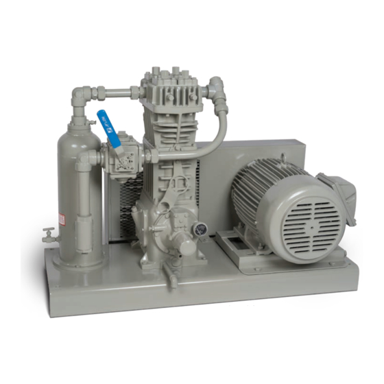
Page 6: Compressor Construction Features
With the exception of the small size model 91 compressor, and the atmosphere. A typical liquid transfer-vapor all compressor crankcases are lubricated by an automotive recovery compressor package is shown in figure 1.3A. - Page 7 Spacers Suction valve Valve plate post Discharge valve Suction valve Figure 1.3B: Pressure lubrication system (not available on Model 91). seat bumper Piston rod packing is used to seal the gas in the Valve gasket Valve gasket compression chamber and prevent crankcase oil from entering the compressor cylinder.
-
Page 8: Chapter 2—Installing Your Corken Compressor
(compressor, baseplate, motor, Baseplate should etc.). For Models 91, 291, 491, and 691, the baseplate be a maximum of 4" high should be secured to the foundation using 1/2" diameter Concrete x 12"... - Page 9 Back check valve Hydrostatic relief valve Relief valve 4-Way valve Vapor line to rail car (inbound bulk transport) Bury or insulate in cold climate areas Vapor line to liquid phase Vapor line to truck Vapor line to gas phase in storage tank trailer or tank in storage tank (local transport)
- Page 10 Back check valve Hydrostatic releif valve Relief valve 4-Way valve Vapor line rail car (in-bound bulk transfer) Bury or insulate in cold climate areas Vapor line to gas phase in storage Vapor line to liquid phase in storage 4-way Valve Operation Valve Position Service to Perform...
-
Page 11: Liquid Traps
Corken’s most sophisticated trap provides the most Corken offers three types of liquid traps for removal of thorough liquid separation. This trap is larger and is liquids in the gas stream (see figure 2.4A). The simplest is ASME code stamped. -
Page 12: Driver Installation / Flywheels
No motor manufacturer will guarantee their explosion proof or totally enclosed Corken gas compressors are used for a wide variety of (TEFC) motor against damage from moisture. gases in a multitude of operating conditions. They are... - Page 13 Given the relatively preferred for Corken compressors. small volume of oil used in the crankcase of a Corken Oil with a low viscosity index tends to thin out as the oil compressor, and the critical nature of the services temperature increases.
-
Page 14: Relief Valves
NEVER be used in Corken compressors. If motor to maintain clean, undiluted oil. Each time the oil is oil is used in a Corken compressor, it should have an changed, the oil filter (Corken part number 4225) should API Service of SJ or better . Multigrade motor oils such also be changed. -
Page 15: Truck Mounted Compressors
2 .8 Truck Mounted Compressors Corken compressors may be mounted on trucks to perform liquid transfer operations as described in section 1.1. The compressor should be mounted so the inspection plate is accessible for packing adjustment. The compressor must be protected against liquid as explained in section 2.4 and a relief valve must be installed in the discharge piping before the first downstream shutoff valve. -
Page 16: Chapter 3—Starting Up Your Corken Compressor
Visual inspection often will indicate if the belts are properly aligned, but use of a square is the best method. Corken compressor models 291 through 891 are equipped with an automatically reversible gear type oil The flywheel is mounted on the shaft via a split, tapered... -
Page 17: Startup Check List
91, proceed to section 3.4). It is essential to ensure 5. Check all mounting shims, cylinder and piping the pumping system is primed and the oil pressure is supports to ensure that no undue twisting forces exist properly adjusted in order to assure smooth operation. -
Page 18: Chapter 4—Routine Maintenance Chart
It is possible, of course, that the on models 91, 291, 491, 691 and 891 compressors. Since pressure gauge itself is faulty. more than one suction valve arrangement is available for... - Page 19 2. Adjusting screw and discharge opening in the head. NOTE: The spec 3. Relief ball spring 3 suction valves for a model 91 and 291 compressor are pre-set so no adjustments to liquid relief pressure 4. Relief ball are necessary.
-
Page 20: Heads
4. Piston rings and expanders may then be easily signs of wear or damage. Valve caps sealed by flat removed and replaced. Corken recommends replacing metals gaskets should be reinstalled with new gaskets. expanders whenever rings are replaced. To determine if rings should be replaced, measure the radial 7. -
Page 21: Pistons
6. Before installing the new piston, measure the thickness 13. Reinstall the head (see section 5.2) and follow standard of the existing shims. For Models 91, 291, and 491, the startup procedure. (Note: Some compressors may shims are placed between the thrust washer and piston have self-locking nuts without roll pins.) -
Page 22: Piston Rod Packing Adjustment
15. Replace the previously removed valves. Best results will be obtained if new valve gaskets are used. 16. Follow standard startup procedures. 5 .5 Piston Rod Packing Adjustment Piston rod packing should be adjusted or replaced ( Y ) ( Y ) whenever leakage becomes noticeable. - Page 23 Disassembly of Packing Workmanship: 1. Depressurize and open the compressor. Your Corken compressor is a precision piece of equipment 2. Remove head, pistons and cylinder. with very close tolerances. Treat it as such. Never beat on it to get parts in or out.
- Page 24 Model 891 Compressor 8. Install packing installation cone part number 4005 over the threaded end of the piston rod. (Refer to Appendix E for packing assembly details) 9. Carefully slip the packing cartridge over the piston rod; Disassembly of Packing (D-Style) otherwise, you may damage the lips of the packing rings.
-
Page 25: Bearing Replacement For Crankcase And Connecting Rod
5 . 7 . 1 Wrist Pin Bushing Replacement 3. Segmented packing: 1. To replace the wrist pin bushing, remove the retainer NOTE: The instructions below are for packing rings that position the wrist pin in the crosshead. specification “J” . Depending on the packing specification used in your compressor, the order of 2. -
Page 26: Oil Pump Inspection
Figure 5.7.3: Bearing carrier replacement. pump shaft slot is aligned with the pin in the crankshaft. 2. Inspect the gears in the oil pump for corrosion or Make sure to install the bearing carrier gasket so the oil pitting and replace if necessary. passage hole is not blocked (see figure 5.7.3). -
Page 27: Chapter 6—Extended Storage Procedures
Following a few simple procedures will greatly minimize 5. Plug all openings to prevent entry of insects and the risk of corrosion and damage. Corken recommends moisture. (The cylinders may also be protected by the the following precautions to protect the compressor... -
Page 28: Gasket Sets
6 .2 Gasket Sets Model 491 Gasket Set (1481-X6A) Part No . Description Model 91 Gasket Set (2526-XA) 1418 Valve gasket (aluminum) Part No . Description 1480 Center headbolt gasket (steel) 2-235A O-ring (Buna-N) 1488 Inspection plate gasket 2526 Crankcase gasket... - Page 29 Model 891 Gasket Set (3970-X1A) Part No . Description 1281 Filter screen screw gasket 1761 Crankcase gasket 2-036A O-ring (Buna-N) 2-231A O-ring (Buna-N) 2-238A O-ring (Buna-N) 2114 Valve gasket (aluminum) 2131 Bearing carrier gasket 4127 Lubricator gasket 1760 Inspection plate gasket 2-031A O-ring (Buna-N) 2-228A...
-
Page 30: A. Model Number Identification Code And Available Options
Appendix A—Model Number Identification Code and Available Options Reciprocating Vertical Compressors (Plain Style) LPG and Anhydrous Ammonia Models Model Number Base Model # Plain Style Base X X X X X X X X X X Inlet 3/4" NPT 3/4" NPT 1-1/4"... - Page 31 Appendix A—Model Number Identification Code and Available Options Reciprocating Vertical Compressors (D-Style) Double-acting, Single-stage Models Model Number Base Model # D891 FD891 D-Style Base X X X X X X X X X X Inlet 2" weld 2" Class 300 RF (Double Outlet 2"...
-
Page 32: B. Specifications
Appendix B—Specifications for Vertical Single-Acting Models 91–691 Equipment Type and Options Applications Single-acting, vertical, reciprocating piston type vapor compressor Bulk transfer Tank evacuation Single packed rod Vapor recovery Gas scavenging NPT or Class 300 RF connections Features and Benefits Self-lubricating piston rings:... - Page 33 Appendix B—Specifications for Vertical Single-Acting Models 91–691 Material Specifications Part Model Standard Material Head, Cylinder Ductile iron ASTM A536 Crosshead guide crankcase, flywheel, bearing carrier Gray iron ASTM A48, Class 30 Flange Ductile iron ASTM A536 91, 291 17-4 PH stainless steel...
- Page 34 Appendix B—Specifications for Vertical Single-Acting Models 91–891 Bolt Torque Values (in ft•lb) Model Connecting rod bolt Bearing carrier Bearing cover Crankcase inspection plate Crosshead guide Cylinder to head Valve cover plate bolt — — Valve holddown screw Piston locknut Piston screw Valve cap with gaskets —...
- Page 35 Appendix B—Specifications for Vertical Single and Double-Acting Models 91–891 Clearances and Dimensions for Single-Acting Models Model (M crankcase) 0.020 0.020 0.000 0.020 0.025 “X” piston clearance figure 5.4A and 5.4B 0.044 0.044 0.024 0.044 0.040 Clearance from connecting rod bearing to 0.001...
- Page 36 Appendix B—Specifications for Vertical Double-Acting Model D891/FD891 Equipment Type and Options Applications Double-acting, vertical, reciprocating piston type vapor compressor Bulk transfer LTVR and scavenger Double packed rod Truck, tank, applications railcar, barge Slip-on weld connections or Class 300 RF flanges unloading Emergency evacuation...
- Page 37 Appendix B—Specifications for Vertical Double-Acting Model D891/FD891 Material Specifications Part Standard Material Head, cylinder, and cylinder cap Ductile iron ASTM A536 Crosshead guide Gray iron ASTM A48, Class 30 Crankcase, flywheel Gray iron ASTM A48, Class 30 Bearing carrier Gray iron ASTM A48, Class 30 Flange ASTM A36 carbon steel (D891 only) Valve seat, bumper...
-
Page 38: C. Compressor Selection
Appendix C—Compressor Selection Compressor Mounting Selections Suction & discharge Standard 107 Items pressure gauges Relief valve connection Interconnecting piping • Steel baseplate • 40 Micron strainer • V-belt drive • Non-lube 4-way valve Non-lube, full port, • Adjustable driver side base •... - Page 39 Driver sheaves: 91 - 2 belts; 291, 491 - 3 belts; 691 - 4 belts. The piping sizes shown are considered minimum. If the length exceeds 100 ft., use the next larger size.
- Page 40 Driver sheaves: 91 - 2 belts; 291, 491 - 3 belts; 691 - 4 belts. The piping sizes shown are considered minimum. If the length exceeds 100 ft., use the next larger size.
- Page 41 Driver sheaves: 91 - 2 belts; 291, 491 - 3 belts; 691 - 4 belts. The piping sizes shown are considered minimum. If the length exceeds 100 ft., use the next larger size.
-
Page 42: D. Outline Dimensions
Appendix D—Outline Dimensions Appendix D—Outline Dimensions Models 91–691 and F91–F691 Bare with Flywheel Inlet Outlet Model 1-13/16 2-3/8 3-11/16 13/32 6-1/4 3-7/8 25-5/16 22-11/16 91, F91 (46.0) (60.3) (93.7) (10.3) (15.9) (158.8) (98.4) (642.9) (127.0) (576.3) 3-3/8 4-1/8 3-11/16 7/16... - Page 43 Appendix D—Outline Dimensions Appendix D—Outline Dimensions Models 91 with -107 or -107A Mounting (Model -107A Shown Below) All dimensions are in inches (millimeters).
- Page 44 Appendix D—Outline Dimensions Model 291 with 107 Mounting (Motor Frames Up to 215T) All dimensions are in inches (millimeters).
- Page 45 Appendix D—Outline Dimensions Model 291 with 107 Mounting (Motor Frames 254T and Up) All dimensions are in inches (millimeters).
- Page 46 Appendix D—Outline Dimensions Model 491 with 107 Mounting All dimensions are in inches (millimeters).
- Page 47 Appendix D—Outline Dimensions Model 691 with 107 Mounting All dimensions are in inches (millimeters).
- Page 48 Appendix D—Outline Dimensions Models 91–691 with -109 or -109A Mounting (Model -109A Shown Below) Model 1-3/16 5-1/4 13-5/16 31-1/2 1-1/2 31-3/16 91-109, -109A — (30.2) (133.4) (304.8) (338.1) (800.1) (38.1) (381.0) (863.6) (792.2) 15-3/4 39-1/2 1-1/2 30-7/8 291-109, -109A —...
- Page 49 Appendix D—Outline Dimensions Model D891 Bare with Flywheel 5-7/16 5-7/16 (139) (139) Suction valve unloaders (optional) Inlet 2" Discharge slip-on 2" slip-on weld ange weld ange 1/4"-18 NPT for drain-both sides (1,092) 35-5/8 (905) 21.2 (539) 24-7/16 diameter (621) 2-1/8 (54) 8-1/4 (210) Crankcase...
- Page 50 Appendix D—Outline Dimensions Model FD891 Bare with Flywheel (152) (152) Suction Discharge pressure pressure gauge gauge (optional) (optional) Inlet: Outlet: 2" Class 2" Class 300 RF 300 RF ange ange Suction valve unloaders (optional) Compressor wrench Crankcase oil gauge 35-5/8 (905) 21.2 43-3/16...
- Page 51 Appendix D—Outline Dimensions Model D891 with 103 Mounting All dimensions are in inches (millimeters).
- Page 52 Appendix D—Outline Dimensions Model FD891 with 103 Mounting All dimensions are in inches (millimeters).
- Page 53 Appendix D—Outline Dimensions Model FD891 with 107 Mounting All dimensions are in inches (millimeters).
- Page 54 Appendix D—Outline Dimensions Model D891 with 107B Mounting All dimensions are in inches (millimeters).
- Page 55 Appendix D—Outline Dimensions Model FD891 with 107B Mounting All dimensions are in inches (millimeters).
- Page 56 Appendix D—Outline Dimensions Model D891 with 109B Mounting All dimensions are in inches (millimeters).
-
Page 58: E. Parts Details
Appendix E—Parts Details for 91 and F91 Head and Valve Assembly 91 Head Assembly Valve Holddown Assemblies Suction Suction Discharge Spec 3 Spec 4 All Specs F91 Head Assembly Valve Assemblies Suction Valve Spec 3 Suction Valve Discharge Valve CAUTION: Always relieve pressure in the... - Page 59 Appendix E—Parts Details for 91 and F91 Head and Valve Assembly Head and Valve Bill of Materials Part No . Description Qty . No . 2374 Head (model 91) 2374-X Head assembly (model 91, spec 3) 2374-X1 Head assembly (model 91, spec 4)
- Page 60 Appendix E—Parts Details for 91 and F91 Head and Valve Assembly Piston—Bill of Materials Piston Diameter 3" (7 .62 cm) Part No . Description Qty . No . 7002-010TP100A Screw (socket head) 7207-010A Lock washer 1983 Head (iron) 1775 Ring expander...
- Page 61 Appendix E—Parts Details for 91 and F91 Packing Assembly Packing—Bill of Materials Part No . Description Qty . No . 2242 Cylinder 2-235_ O-ring for cylinder 5000-137 Retainer ring 1012 Washer 1628 Packing spring 1714 Packing box washer 1453-1 Male packing ring...
- Page 62 Appendix E—Parts Details for 91 and F91 Connecting Rod Assembly Connecting Rod—Bill of Materials Qty . per Part No . Description No . Compressor 1132-X2 Crosshead assembly 1498 Retainer ring 2505 Wrist pin 1846-X a, b Wrist pin bushing 1599...
- Page 63 Appendix E—Parts Details for 91 and F91 Flywheel Assembly Back Side Flywheel—Bill of Materials Part No . Description Qty . No . 3271 Flywheel (14" O.D., 2 groove) Hub with three bolts and H SF-1.125 lockwashers Assembly Number Assembly Name...
- Page 64 Appendix E—Parts Details for 91 and F91 Crankcase Assembly...
- Page 65 Appendix E—Parts Details for 91 and F91 Crankcase Assembly Packing—Bill of Materials Part No . Description Qty . No . 3259 Oil seal 1450 Groove pin (1/8" x 1") 7001-037NC075A Hex head (3/8"–16 x 3/4", grade 5) 3260 Bearing carrier...
- Page 66 Appendix E—Parts Details for 291 and F291 Head and Valve Assembly 291 Head Assembly Valve Holddown Assemblies Suction Suction Discharge Spec 3 Spec 4 All Specs F291 Head Assembly Valve Assemblies Details Suction Valve Spec 3 Suction Valve Discharge Valve Spec 4 All Specs CAUTION: Always relieve pressure in the...
- Page 67 Appendix E—Parts Details for 291 and F291 Head and Valve Assembly Head and Valve Bill of Materials Part No . Description Qty . No . 2912 Head (model 291) Head assembly 2912-X1 (model 291, spec 3) Head assembly 2912-X2 (model 291, spec 4) Head 4300 (model F291, Class 300 RF flange)
- Page 68 Appendix E—Parts Details for 291 and F291 Piston Assembly Piston—Bill of Materials Piston Diameter 3" (7 .62 cm) Part No . Description Qty . No . 7002-010TP100A Screw (socket head) 7207-010A Lock washer 1983 Head (iron) 1775 Ring expander 1772 Piston ring 1482 Locknut...
- Page 69 Appendix E—Parts Details for 291 and F291 Packing Assembly Packing—Bill of Materials Part No . Description Qty . No . 2913-1 Cylinder 2-235_ O-ring (cylinder) 5000-137 Retainer ring 1012 Washer 1628 Packing spring 1714 Packing box washer 1453-1 Male packing ring 1454 Packing 1452-1...
- Page 70 Appendix E—Parts Details for 291 and F291 Connecting Rod Assembly Connecting Rod—Bill of Materials Qty . per Part No . Description No . Compressor 1132-X2 Crosshead assembly 1498 Retainer ring 2505 Wrist pin 1846-X a, b Wrist pin bushing 1599 Bolt 1889-X Connecting rod assembly...
- Page 71 Appendix E—Parts Details for 291 and F291 Flywheel Assembly Back Side Flywheel—Bill of Materials Part No . Description Qty . No . 2549 Flywheel (16" O.D., 3 groove) Hub with three bolts and H SF-1.250 lockwashers Assembly Number Assembly Name Flywheel assembly (flywheel, hub, 2549-X1 and three bolts)—standard...
- Page 72 Appendix E—Parts Details for 291 and F291 Crankcase Assembly 17 (Assembly) 25 24 39 (assembly) 46 9 43 (assembly)
- Page 73 Appendix E—Parts Details for 291 and F291 Crankcase Assembly Packing Assembly Bill of Materials Part No . Description Qty . Part No . Description Qty . No . No . 2-228A O-ring (Buna-N, pump cover) 1278 Oil seal 4222-X Oil filter assembly 7001-037NC075A Bolt (hex head, 3/8"-16 x 3/4") 2957...
- Page 74 Appendix E—Parts Details for 491 and F491 Head and Valve Assembly 491 Head Assembly Valve Holddown Assemblies Suction Suction Discharge Spec 3 Spec 4 All Specs Suction Discharge F491 Head Assembly Suction Valve Assemblies Suction Valve Spec 3 Discharge Suction Valve Discharge Valve Spec 4 All Specs...
- Page 75 Appendix E—Parts Details for 491 and F491 Head and Valve Assembly Head and Valve Bill of Materials Part No . Description Qty . Valve Assembly No . Assembly Name No . No . 3712 Head (model 491, ductile iron) 101. 2438-X Suction valve assembly—spec 4 Head...
- Page 76 Appendix E—Parts Details for 491 and F491 Piston Assembly Piston—Bill of Materials Piston Diameter 4" (10 . 1 6 cm) Part No . Description Qty . No . 7002-025TP125A Screw (socket head) 7207-025A Lock washer 1985 Head (iron) 1776 Ring expander 1773 Piston ring 1482...
- Page 77 Appendix E—Parts Details for 491 and F491 Packing Assembly Packing—Bill of Materials Part No . Description Qty . No . 3713 Cylinder (491 with O-ring) 2-243_ O-ring (cylinder) 5000-137 Retainer ring 1012 Washer 1628 Packing spring 1714 Packing box washer 1453-1 Male packing ring 1454...
- Page 78 Appendix E—Parts Details for 491 and F491 Connecting Rod Assembly Connecting Rod—Bill of Materials Qty . per Part No . Description No . Compressor 1384-X Crosshead assembly 1498 Retainer ring 1496 Wrist pin 1495-X a, b Wrist pin bushing 1492 Bolt 1490-X Connecting rod assembly...
- Page 79 Appendix E—Parts Details for 491 and F491 Flywheel Assembly Back Side Flywheel—Bill of Materials Part No . Description Qty . No . 2549 Flywheel (16" O.D., 3 groove) Hub with three bolts and H SF-1.375 lockwashers Assembly Number Assembly Name Flywheel assembly (flywheel, hub, 2549-X and three bolts)—standard...
- Page 80 Appendix E—Parts Details for 491 and F491 Crankcase Assembly 25 24 39 (assembly) 46 9 43 (assembly)
- Page 81 Appendix E—Parts Details for 491 and F491 Crankcase Assembly Packing Assembly Bill of Materials Part No . Description Qty . Part No . Description Qty . No . No . 2-228A O-ring (Buna-N, pump cover) 4438 Oil seal 7001-037NC075A Bolt (hex head, 3/8"-16 x 3/4") 4222-X Oil filter assembly (external) 2-1.
- Page 82 Appendix E—Parts Details for 691 and F691 Head and Valve Assembly 691 Head Assembly Valve Holddown Assemblies Suction Suction Discharge Spec 3 Spec 4 All Specs F691 Head Assembly Valve Assemblies Suction Valve Spec 3 Suction Valve Discharge Valve Spec 4 All Specs CAUTION: Always relieve pressure in the unit before attempting any repairs.
- Page 83 Appendix E—Parts Details for 691 and F691 Head and Valve Assembly Head and Valve Bill of Materials Part No . Description Qty . Valve Assembly No . Assembly Name No . No . 3458 Head (model 691) 101. 3948-2X Suction valve assembly—spec 3 Head 102.
- Page 84 Appendix E—Parts Details for 691 and F691 Piston Assembly Piston—Bill of Materials Piston Diameter 4 .5" (11 .43 cm) Part No . Description Qty . No . 7002-025TP125A Screw (socket head) 7207-025A Lock washer 1987 Head, iron 1740 Ring expander 1739 Piston ring 1482...
- Page 85 Appendix E—Parts Details for 691 and F691 Packing Assembly Packing—Bill of Materials Part No . Description Qty . No . 3457 Cylinder (model 691) 2-247_ O-ring (cylinder) 1749-X Cartridge holddown screw 5000-175 Retainer ring 1731 Packing spring 1728 Packing washer 1724 Male packing ring 1725-2...
- Page 86 Appendix E—Parts Details for 691 and F691 Connecting Rod Assembly Connecting Rod—Bill of Materials Part No . Qty . per Description No . Compressor Spec M Only 3544-X4 Crosshead assembly 3590 Retainer ring 3540 Wrist pin 3541-X Wrist pin bushing a, c 1726 Bolt...
- Page 87 Appendix E—Parts Details for 691 and F691 Flywheel Assembly Back Side Flywheel—Bill of Materials Part No . Description Qty . No . 1762 Flywheel (19.5" O.D., 4 groove) Hub with three bolts and H E-2.125 lockwashers Assembly Number Assembly Name Flywheel assembly (flywheel, hub, 1762-X and three bolts)—standard...
- Page 88 Appendix E—Parts Details for 691 and F691 Crankcase Assembly Inside of Bearing Carrier (Includes all parts shown except #50 and #51) Oil Passage Hole Important! Line up hole in gasket with oil passage hole. Pump Cover Oil/Filter Adapter Pumpside of adapter shown for proper orientation of cover and location of pump cover pin.
- Page 89 Appendix E—Parts Details for 691 and F691 Crankcase Assembly Packing—Bill of Materials Part No . Description Qty . Part No . Description Qty . No . No . 2851 Spring guide 1737 Bearing cone 2852 Oil pump spring 3638-1 Spacer 1284 Crankshaft orifice 3219...
- Page 90 Appendix E—Parts Details for D891 and FD891 Head and Valve Assembly 891 Head Valve Holddown Valve Holddown Assembly (4-1/2") Assembly (4-1/2") Suction Discharge D891 D891 cover cover plate plate FD891 FD891 cover cover plate plate CAUTION: Always relieve pressure in the unit before attempting any repairs.
- Page 91 Appendix E—Parts Details for D891 and FD891 Piston Piston—Bill of Materials Piston Diameter 4 .5" (11 .43 cm) Part No . Description Qty . No . 7002-025TP100A Screw (orlo, gr. 8, torque to 8 ft•lbs) 3927 Piston cap 2902 Shim washer (thick) req.
- Page 92 Appendix E—Parts Details for D891 and FD891 Crosshead Guide D891 Cylinder FD891 Cylinder Valve openings Valve openings Valve openings Valve openings Crosshead Guide—Bill of Materials Part No . Description Qty . No . 3922 Cylinder (model D891) Packing barrels Cylinder and cartridges 4851 (model FD891, Class 300 RF flange)
- Page 93 Appendix E—Parts Details for D891 and FD891 Packing Packing—Bill of Materials Specification “J” Part No . Description Qty . No . 3926 Packing barrel (4-1/2") 2-238_ O-ring a, c 3906 Crush gasket Packing cup (Not included in 3817 3810-X1 packing set) 2-036_ O-ring (cup) a, d...
- Page 94 Appendix E—Parts Details for D891 and FD891 Connecting Rod Assembly Connecting Rod—Bill of Materials Qty . per Part No . Description No . Compressor 3544-X3 Crosshead assembly 3590 Retainer ring 3540 Wrist pin 3541-X a, c Wrist pin bushing 1726 Bolt 3785-X1 Connecting rod assembly...
- Page 95 Appendix E—Parts Details for D891 and FD891 Flywheel Assembly Back Side Flywheel—Bill of Materials Part No . Description Qty . No . 3852 Flywheel (21.2" O.D., 5 groove) Hub with three bolts and H J-2.125 lockwashers Assembly Number Assembly Name Flywheel assembly (flywheel, hub, 3852-X and three bolts)
- Page 96 Appendix E—Parts Details for D891 and FD891 Crankcase Assembly Inside of Bearing Carrier (Includes all parts shown except #50 and #51) Oil Passage Hole Important! Line up hole in gasket with oil passage hole. Pump Cover Oil/Filter Adapter Pumpside of adapter shown for proper orientation of cover and location of pump cover pin.
- Page 97 Appendix E—Parts Details for D891 and FD891 Crankcase Assembly Packing Assembly Bill of Materials Part No . Description Qty . Part No . Description Qty . No . No . 2851 Spring guide 1737 Bearing cone 2852 Oil pump spring 3638-1 Spacer 1284...
-
Page 98: F. Troubleshooting
Appendix F—Troubleshooting In most cases, problems with your Corken gas compressor compressors along with a list of possible causes. If you can be solved quite simply. This chart lists some of the are having a problem which is not listed, or if you cannot more frequent problems that occur with reciprocating find the source of the problem, consult the factory. - Page 100 Solutions beyond products... CORKEN, INC. • A Unit of IDEX Corporation 3805 NW 36th Street, Oklahoma City, OK 73112 Phone (405) 946-5576 • Fax (405) 948-7343 Visit our website at www.corken.com or e-mail us at cocsalesdept@idexcorp.com @CorkenInc Printed in the U.S.A.
Need help?
Do you have a question about the 91 and is the answer not in the manual?
Questions and answers