Table of Contents
Advertisement
ORIGINAL INSTRUCTIONS
Installation, Operation
& Maintenance Manual
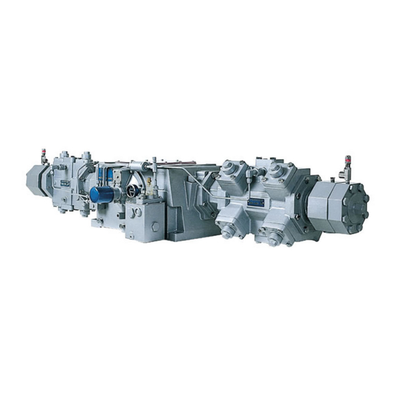
Plain & T-Style Double-Acting Gas Compressors
Models HG601, HG602, THG601 & THG602 Series
Model HG601EE
(Plain style)
Warning: (1) Periodic inspection and maintenance of Corken products is essential. (2) Inspection, maintenance and installation of
Corken products must be made only by experienced, trained and qualified personnel. (3) Maintenance, use and installation of Corken
products must comply with Corken instructions, applicable laws and safety standards. (4) Transfer of toxic, dangerous, flammable or
explosive substances using Corken products is at user's risk and equipment should be operated only by qualified personnel according
to applicable laws and safety standards.
Model THG602BE
(T-style)
Solutions beyond products...
IJ100F
Advertisement
Table of Contents

Subscribe to Our Youtube Channel
Related Manuals for Corken HG601 Series


Summary of Contents for Corken HG601 Series
- Page 1 Warning: (1) Periodic inspection and maintenance of Corken products is essential. (2) Inspection, maintenance and installation of Corken products must be made only by experienced, trained and qualified personnel. (3) Maintenance, use and installation of Corken products must comply with Corken instructions, applicable laws and safety standards. (4) Transfer of toxic, dangerous, flammable or explosive substances using Corken products is at user’s risk and equipment should be operated only by qualified personnel according...
- Page 2 Corken One Year Warranty CORKEN, INC. warrants that its products will be free from defects in material and workmanship for a period of one year from date of installation, provided that the warranty shall not extend beyond twenty-four (24) months from the date of shipment from CORKEN.
-
Page 3: Table Of Contents
Table of Contents Chapter 1—Introduction . . . . . . . . . . . . . . . . . . . . . . . . . . . . . . . . . . . . . . . . . . . . . . . . . . . . . . . . . . . . . . . . . . . . . . . . 4 Chapter 2—Installation of the Compressor . -
Page 4: Chapter 1-Introduction
Corken's horizontal compressor is a double-acting reciprocating compressor; however, when an optional blank valve is used, the compressor is single acting. Corken horizontal compressors have a large number of configurations to fit individual requirements. They are manufactured as single stage- or two-stage units. - Page 5 Flywheel Crankshaft journal, connecting rod bearings, wrist pins, and crossheads: Pressure lubricated by an oil pump with oil ltered by a 10-micron spin on lter. Inner oil wiper ring set Inner packing set Oil de ector ring Middle packing set Outer packing set Inner distance piece (Barrier 1)
-
Page 6: Chapter 2-Installation Of The Compressor
2 .3 Piping consult Corken. Check local safety regulations and building codes to assure installation will meet local safety standards. Piping design and installation is as important as the foundation for trouble-free compressor operation. -
Page 7: Liquid Trap
Install, use, and maintain this equipment according to side of the compressor from liquid entry. This may be Corken instructions and all applicable federal, state, and done by installing a check valve on the discharge side of local laws and codes. -
Page 8: Driver Installation And Flywheels
If the compressor is equipped with a liquid trap not NOTE: No motor manufacturer will guarantee their manufactured by Corken, make sure it is adequately explosion proof or totally enclosed (TEFC) motor sized; otherwise, it may not be able to remove the liquid against damage from moisture . - Page 9 Corken compressors. The minimum Viscosity Index for are used, selecting the appropriate high quality oil is oils used in Corken compressors is 95 (VI is a unit-less the most economical choice. It will help ensure the number). This is particularly important when operating dependability and longevity of the compressor.
- Page 10 -58°F (-50°C) Royal Purple Uni-Temp 68 -51°F (-46°C) Consult Corken for oil recommendations in very hot climates—ambient temperatures consistently above 100°F (38°C). Oil type: C=Conventional, S=Synthetic, B=Conventional/Synthetic blend Information available from oil manufacturers at the time of publication. Mobil SHC oils are synthetic oils which require that the crankcase be flushed of residual mineral oil.
- Page 11 Each Compressor cylinders operate at higher temperatures time the oil is changed, the oil filter (Corken part number than the crankcase, so oils used in this service often have 4225) should also be changed.
-
Page 12: Relief Valves
These oils typically also have properties that prevent corrosion and carbon buildup in the cylinders and valves. Contact Corken is assistance is needed in selecting a For all applications, shutdown/alarm sensors (switches suitable cylinder lubricating oil. Oil manufacturers are or transmitters) provide worthwhile protection that may often a good source for this information as well. -
Page 13: Chapter 3-Starting Up The Compressor
Chapter 3—Starting Up the Rotate unit manually to ensure running gear functions properly. Replace the crankcase inspection plate and Compressor proceed with startup. The initial operation of the compressor is the most critical 3 .2 Flywheel and V-belt Alignment time it will ever face. READ ALL OF CHAPTER TWO BEFORE PROCEEDING TO THE STARTUP CHECKLIST. -
Page 14: Crankcase Oil Pressure Adjustment
NOTE: 1) When using five individual V-belts (5V or 5VX), 1/4 to 3/8 inches (6.4 to 9.5 mm) of movement is normal. 2) When using five banded V-belts, movement will be much less due to the stiffness of the banded V-belt design. Figure 3.2C The oil pressure should be about 20 psi (1.4 bars) Set Screw... -
Page 15: Compressor Speed And Rotation Direction
3 .6 Force Feed Cylinder Rotation Direction Lubrication (Lubed models only) The lubrication system of the Corken horizontal An external lubricator is bolted directly to the crankcase compressor is designed to operate at a minimum of 400 and is driven by a chain inside the crankcase at 80% RPM. -
Page 16: Variable Clearance Heads (Vch)
3 . 7 Variable Clearance Heads (VCH) 8. Check V-belt tension and alignment. Check drive alignment on direct drive units. Variable clearance head (VCH) assemblies (outboard) 9. Rotate unit by hand. Check flywheel for wobble or play. allow adjustment of the compressor when operating conditions change. -
Page 17: Chapter 4-Routine Maintenance Chart
Chapter 4—Routine Maintenance Chart Item to Check Daily Weekly Monthly Yearly Months Crankcase oil pressure Compressor discharge pressure Overall visual check Crankcase oil level Drain liquid from accumulation points Drain distance pieces Clean cooling surfaces on compressor and intercooler (if any) Lubricator supply tank level (if any) Check belts for correct tension Inspect valve assemblies... -
Page 18: Heads
Valve Inspection and/or Replacement replaced. Replacement is usually preferable although repair parts are available. If valve plates are replaced, Before removing and inspecting the valves, begin by seats should also be lapped until they are perfectly depressurizing and purging (if necessary) the unit and smooth. -
Page 19: Piston Rings And Piston Ring Expander Replacement
Appendix B. particularly under high temperature conditions. 5 .4 Pistons CORKEN uses one of the best PTFE ring formulations available. The normal life expectancy is approximately While reading the following instructions, refer to 2,200 hours of continuous service within recommended Appendix D for parts details . -
Page 20: Cylinder Replacement
“X” at the outboard end of the piston as (Corken #3905) over piston rod threads. This shown in the Appendix B. If this measurement does will aid and protect packing during installation. - Page 21 Cleanliness: head bolts that attach the packing cartridge cap to the adapter. It is not normally necessary to Sealing a reciprocating piston rod is a very difficult task. remove the adapter from the crankcase in order to In order to create the best seal possible between the disassemble or reassemble the packing.
- Page 22 b. Install the oil wiper ring set, packing washer and d. Install a purge packing cup with O-ring and biased inner retainer ring into the crankcase side of the packing set (tangent-tangent with springs toward packing cartridge body. crankcase [sTT]) into cylinder side of packing cartridge body.
- Page 23 If the packing components are not easily removable, it may be necessary to use Corken Packing Removal 3. Refer to Appendix D and identify the correct model Tool 4789-X. Referring to figure 5.6A, orient the...
- Page 24 10. Inner Packing: Remove the purge packing cup, Step 1 segmented packing, oil wiper cup, oil wiper ring set, etc. from the cylinder side of the packing cartridge adapter. Assembly of Packing—T-style Compressor Packing removal Models THG601 and THG602 tool (4789-X) Lever 1.
- Page 25 Step 1 Step 3 Packing assembly Packing assembly tool (4794-X) tool (4794-X) Slotted clamp Inner packing set End plate Packing cartridge Purge packing cup adapter End plate Biased packing set (TTs) Figure 5.6C: Packing assembly Figure 5.6E : Packing assembly Step 2 Step 4 Packing assembly...
-
Page 26: Bearing Replacement For Crankcase And Connecting Rod
5. Middle Packing i. Install the packing cartridge cap in the adapter. Be sure the mark previously made on the packing a. Install packing cup with O-ring. Install segmented cartridge cap is oriented up because the packing packing set (tangent, tangent) with pin side towards cartridge cap can only be installed in one position. - Page 27 Oil seal Bearing cover Shim Bearing cup Crankcase Bearing cone Drive pin Crankshaft Bearing cone Flywheel key Bearing cup Bearing carrier gasket Bearing carrier Spacer Drive sprocket Link pin Make sure this hole is aligned with the oil-passage hole on the bearing carrier. Backside of bearing carrier Align slot with the pin located...
- Page 28 Crankcase inspection plate: Backside of Fill crankcase with oil through oil lter adapter this opening. Pump shaft bushing Oil suction Align pin with slot on pump shaft adapter. Oil lter O-ring Spring Pump shaft adapter Align slot with Spring guide the pin at the end of Oil lter adapter the crankshaft.
-
Page 29: Oil Pump Inspection
Appendix B. Following a few simple procedures will greatly minimize the risk of the unit becoming corroded and damaged. Corken recommends the following precautions to protect 5 .8 Oil Pump Inspection the compressor during storage: If the compressor operates for a prolonged period with 1. -
Page 30: Gasket Sets
6 .2 Gasket Sets 6 .3 Crankcase and Cylinder Kit Options THG Series Gasket Set Cylinder Description Crankcase Options (frame only) Size 3582-T8SE2 8" Standard head (PTFE, steel) Model Number Lubricator 3582-T8SD2 8" Standard head (Viton , steel) ®1 HG600XXM Not included 3582-T8AE2 8"... -
Page 31: Chapter 7-Safety
2. Corken gas compressors are not to be used for / cleaning operations: pumping liquids. a. Fire protective clothing for compressors used on 3. Corken gas compressors are not to be used with the flammable gases following process gases: b. Hard hat a. - Page 32 startup, clogged oil filters or valve malfunction can result in oil starvation and subsequent damage to the compressor. 16. Safe lifting, transporting, and handling: a. Connect a lifting apparatus, such as a hoist, forklift or sling to the lifting eye(s) on the crankcase of the compressor.
-
Page 34: Model Number Identification Code And Available Options
Appendix A—Model Number Identification Code and Available Options Industrial Horizontal Single Cylinder Compressors Model Number Air Cooled—Single Cylinder Base Model # Plain Style Base X X X X X X X X X X X HG601AX HG601BX HG601CX HG601DX HG601EX HG601FX (Single Cylinder size... - Page 35 Appendix A—Model Number Identification Code and Available Options Reciprocating Vertical Compressors (D-Style) Double-acting, Single-stage Models Model Number Air Cooled—Two Cylinders Base Model # Plain Style Base X X X X X X X X X X X HG601AA HG601BB HG601CC HG601DD HG601EE HG601FF...
- Page 36 Appendix A—Model Number Identification Code and Available Options Reciprocating Horizontal Models (Plain & T-Style) Two-stage (Two Cylinder) Model Number Air Cooled—Two Cylinders Plain Style Base Model # Base X X X X X X X X X X X HG602AB HG602AC HG602AD HG602BC...
- Page 37 Appendix A—Model Number Identification Code and Available Options Continued Reciprocating Horizontal Models (Plain & T-Style) Two-stage (Two Cylinder) Model Number Air Cooled—Two Cylinders Base Model # Plain Style Base X X X X X X X X X X X HG602AB HG602AC HG602AD...
- Page 38 Appendix A—Model Number Identification Code and Available Options Reciprocating Horizontal Models (Plain and T-Style) Two-stage (Two Cylinder) Model Number Air Cooled—Two Cylinders Base Model # Plain Style Base X X X X X X X X X X X HG602BE HG602BF HG602CD HG602CE...
- Page 39 Appendix A—Model Number Identification Code and Available Options Reciprocating Horizontal Models (Plain and T-Style) Two-stage (Two Cylinder) Model Number Air Cooled—Two Cylinders Base Model # Plain Style Base X X X X X X X X X X X HG602DE HG602DF HG602EF (Single...
- Page 40 Appendix A—Model Number Identification Code and Available Options LPG Horizontal Two Cylinder, Single-stage Compressors Model Number Plain Style T-Style Base Model # Plain Style Base X X X X X X X X X X X HG601AA HG601BB THG601AA THG601BB (Single Cylinder size 8"...
-
Page 41: Specifications
Appendix B—Specifications for HG600/THG600 Series Operating Specifications Cylinder Data Cylinder Code Description Cylinder Bore in. (mm) 8.0 (203.2) 6.0 (152.4) 5.0 (127) 4.0 (101.6) 3.25 (82.6) 2.75 (69.9) Maximum allowable working 1,815 (125.1) 330 (22.8) 385 (26.5) 825 (56.9) 1,100 (75.8) 1,320 (91.0) pressure psia (bar g) Piston ring radial thickness... - Page 42 Appendix B—Specifications for HG600/THG600 Series Single-stage Horizontal Compressors Single Cylinder HG601AX HG601BX HG601CX HG601DX HG601EX HG601FX Models THG601AX THG601BX THG601CX THG601DX THG601EX THG601FX Size 8" 6" 5" 4" 3.25" 2.75" Displacement cfm (m /hr) 400 rpm 68.8 (116.9) 38.4 (65.2) 26.4 (44.9) 16.8 (28.5) 10.8 (18.3)
- Page 43 Appendix B—Specifications for HG600/THG600 Series Machine mass The machine mass varies with the compressor model and is shown in the following tables: Horizontal Horizontal Horizontal Horizontal Machine Machine Machine Machine Compressor Compressor Compressor Compressor Mass (kg .) Mass (kg .) Mass (kg .) Mass (kg .) Model...
- Page 44 Appendix B—Specifications for HG600/THG600 Series Material Specifications Part Model No . Standard Material Optional Material Crankcase Ductile iron ASTM A536, Grade 80-55-06 Adapters Ductile iron ASTM A536, Grade 65-45-12 Cylinders Ductile iron ASTM A536, Grade 65-45-12 Cylinder heads (adjustable and standard) All Ductile iron ASTM A536, Grade 65-45-12 Valve caps Ductile iron ASTM A536, Grade 65-45-12...
- Page 45 Appendix B—Specifications for HG600/THG600 Series Bolt Torque Values (in ft•lb) Cylinder Size 2 .75" 3 .25" 4" 5" 6" 8" Connection rod bolt Bearing carrier Bearing cover Crankcase inspection plate Adapter to crankcase or distance piece Distance piece to crankcase Cylinder to adapter Valve cover plate bolt Valve holddown screw...
- Page 46 Appendix B—Specifications for HG600/THG600 Series Piston Clearance—Bottom Dead Center (3 .25" cylinder shown) Top of packing Adapter box cartridge Bottom of piston Cylinder Piston Clearance—Top Dead Center (3 .25" cylinder shown) Adapter Top of piston cap Bottom of head Cylinder Shim washer Piston body X and Y Dimension–Inches (mm)
-
Page 47: Outline Dimensions
Appendix C—Outline Dimensions HG601 Series—Plain Style Single Cylinder 2.125 shaft 2.124 0.5" square keyway 5.53 0.94 (140) 10.10 (24) (257) 3.75 (95) 7.13 (181) 3.38 9.81 (86) (249) 25.45 (646) Adjustable heads 4X 0.88 (22) mtg. holes Lubricator (optional) C1 (adjustable head) 22.18... - Page 48 Appendix C—Outline Dimensions HG601 Series—Plain Style Double Cylinder 2.125 shaft 2.124 0.5" square keyway 5.53 0.94 3.75 (140) (24) (95) 10.10 (257) 7.13 (181) 9.81 (249) 25.45 3.38 (646) (86) Adjustable heads 4X 0.88 (22) mtg. holes Lubricator (optional) C1 (adjustable heads)
- Page 49 Appendix C—Outline Dimensions THG601 Series—T-Style Single Cylinder 2.125 shaft 2.124 0.5" square keyway 5.52 (140) 0.94 3.75 10.10 (24) (95) (257) 7.13 (181) 9.81 (249) 25.45 3.38 (646) (86) Adjustable head 4X 0.88 (22) mtg. holes Lubricator (optional) C1 (adjustable head) 22.18 C (standard head) (563)
- Page 50 Appendix C—Outline Dimensions THG601 Series—T-Style Double Cylinder 2.125 shaft 2.124 0.5" square keyway 0.94 5.53 3.75 (24) (140) (95) 10.10 (257) 7.13 (181) 25.45 (646) Adjustable 9.81 (249) head Adjustable head C1 (adjustable heads) C1 (adjustable heads) C (standard heads) C (standard heads) 6.69 (170)
-
Page 51: Parts Details
Appendix D—Cylinder Head Assembly Details (HG600/THG600 Series) 2 . 7 5" Cylinder Head Adapter (see packing assembly for details) Torque to 65 ft.-lbs. Cylinder—Bill of Materials Qty . per Qty . per Part No . Description Part No . Description No . - Page 52 Appendix D—Cylinder Head Assembly Details (HG600/THG600 Series) 3 .25", 4", and 5" Cylinder Head Adapter (see packing assembly for details) Torque to 65 ft.-lbs. Torque to 65 ft.-lbs. Cylinder—Bill of Materials Cylinder Size Qty . per 3 .25" 4" 5" Description No .
- Page 53 Appendix D—Cylinder Head Assembly Details (HG600/THG600 Series) 6" and 8" Cylinder Head Adapter (see packing assembly for details) Torque to 65 ft.-lbs. Cylinder—Bill of Materials Torque to 65 ft.-lbs. Cylinder Size Qty . per 6" 8" Description No . Cylinder Part No .
- Page 54 Appendix D—Valve Holddown Assembly Details (HG600/THG600 Series) Valve Holddown Assembly (2 . 7 5" only) Valve Holddown Assembly (3 .25", 4", 5", 6", & 8" only) Suction Discharge Suction Discharge Cylinder Diameter Ref . 2 .75" 3 .25" 4" Description No .
- Page 55 Appendix D—Valve Holddown Assembly Details (HG600/THG600 Series) Suction Valve with Unloader Unloader Piston Assembly (3 .25", 4", 5", 6", & 8" only) Details Apply Loctite #290 when assembling See gure A Important: Note seal direction Figure A Material Code Buna-N ®f Neoprene ®f...
- Page 56 Appendix D—Valve Assembly Details (HG600/THG600 Series) 2 . 7 5" Valve 3 .25" Valve Suction Discharge Suction Discharge Cylinder Diameter Ref . 2 .75" 3 .25" 4" 5" Description No . Qty . per Qty . per Qty . per Qty .
- Page 57 Appendix D—Valve Assembly Details (HG600/THG600 Series) 4", 5", 6" Valve 8" Valve Suction Discharge Suction Discharge 6" Only 6" Only Cylinder Diameter 6" 6" 8" 8" Ref . Description (15+ psi suction pressure) (0 to 15 psi suction pressure) (15+ psi suction pressure) (0 to 15 psi suction pressure) No .
- Page 58 Appendix D—Piston Assembly Details (HG600/THG600 Series) 2 . 7 5", 3 .25", 4", 5", and 6" Piston Sizes Piston rod (see connecting rod assembly details for more information) NOTE: See Appendix B for piston clearance specifications. 8" Piston Size Piston rod (see connecting rod assembly for more information) NOTE: See Appendix B for piston clearance...
- Page 59 Appendix D—Piston Assembly Details (HG600/THG600 Series) Piston Assembly—Bill of Materials Cylinder Diameter Ref . Description 2 .75" 3 .25" 4" No . Part No . Qty . Part No . Qty . Part No . Qty . 4365-X1 (light) Piston assembly (iron) 3889-X1 3525-X1 4292-X1 (heavy)
- Page 60 Appendix D—Packing Assembly Details for HG600 Series (Plain Style) 2 . 7 5" Standard Packing Specification NOTE: Cover the end of the piston rod with packing cone (part #3905) before installing packing. For lubricated compressors, the lubricating quill located on the adapter must be removed before packing cartridge can be removed.
- Page 61 Appendix D—Packing Assembly Details for HG600 Series (Plain Style) 2 . 7 5" Purge Packing Specification NOTE: Cover the end of the piston rod with packing cone (part #3905) before installing packing. For lubricated compressors, the lubricating quill located on 65 ft.
- Page 62 Appendix D—Packing Assembly Details for HG600 Series (Plain Style) 3 .25" and 4" Standard Packing Specification NOTE: Cover the end of the piston rod with packing cone (part #3905) before installing packing. For lubricated compressors, the lubricating quill located on the adapter must be removed before packing cartridge can be removed.
- Page 63 Appendix D—Packing Assembly Details for HG600 Series (Plain Style) 3 .25" and 4" Purge Packing Specification O-ring locations NOTE: Cover the end of the piston rod with packing cone (part #3905) before installing packing. For lubricated compressors, the lubricating quill located on the adapter must be removed before packing cartridge can be removed.
- Page 64 Appendix D—Packing Assembly Details for HG600 Series (Plain Style) 5" Standard Packing Specification O-ring locations NOTE: Cover the end of the piston rod with packing cone (part #3905) before installing packing. For lubricated compressors, the lubricating quill located on the adapter must be removed before packing cartridge can be removed. 65 ft.
- Page 65 Appendix D—Packing Assembly Details for HG600 Series (Plain Style) 5" Purge Packing Specification O-ring locations NOTE: Cover the end of the piston rod with packing cone (part #3905) before installing packing. For lubricated compressors, the lubricating quill located on the adapter must be removed before packing cartridge can be removed. 65 ft.
- Page 66 Appendix D—Packing Assembly Details for HG600 Series (Plain Style) 6" and 8" Standard Packing Specification NOTE: Cover the end of the piston rod with packing cone (part #3905) before O-ring locations installing packing. For lubricated compressors, the lubricating quill located on the adapter must be removed before packing cartridge can be removed.
- Page 67 Appendix D—Packing Assembly Details for HG600 Series (Plain Style) 6" and 8" Purge Packing Specification O-ring locations NOTE: Cover the end of the piston rod with packing cone (part #3905) before installing packing. For lubricated compressors, the lubricating quill located on the adapter must be removed before packing cartridge can be removed.
- Page 68 Appendix D—Packing Assembly Details for HG600 Series (Plain Style) Inner Oil Wiper Ring Sets 1. Standard Specification Part number 3816 Oil wiper ring set (Radial, Radial) Crankcase Cylinder Side Side Radial Cut Align pin with Radial Cut (with pin) hole on backside. (without pin) 2.
- Page 69 Appendix D—Packing Assembly Details for HG600 Series (Plain Style) Outer Packing Details for Standard and Purge Packing Specifications 1. Purge Specification Part number 4273 Biased Segmented Packing Set (Tangent, Tangent with springs toward crankcase—sTT) Crankcase Cylinder Side Side O-ring Purge Packing Cup Backup Ring Tangent Cut Align pin with...
- Page 70 Appendix D—Packing Assembly Details for THG600 Series (T-Style) 2 . 7 5" Pad Packing Specification O-ring locations for adapter NOTE: Cover the end of the piston rod 3 (65 ft•lb) with packing cone (part #3905) before installing packing. For lubricated compressors, the lubricating quill located on the adapter must be removed before packing cartridge can be removed.
- Page 71 Appendix D—Packing Assembly Details for THG600 Series (T-Style) 3 .25" and 4" Pad Packing Specification NOTE: Cover the end of the piston O-ring locations rod with packing cone (part #3905) 3 (65 ft•lb) before installing packing. For lubricated compressors, the lubricating quill located on the adapter must be removed before packing cartridge can be removed.
- Page 72 Appendix D—Packing Assembly Details for THG600 Series (T-Style) 5" Pad Packing Specification O-ring locations NOTE: Cover the end of the piston rod with 3 (65 ft•lb) packing cone (part #3905) before installing packing. For lubricated compressors, the lubricating quill located on the adapter must be removed before packing cartridge can be removed.
- Page 73 Appendix D—Packing Assembly Details for THG600 Series (T-Style) 6" and 8" Pad Packing Specification NOTE: Cover the end of the piston rod with O-ring locations packing cone (part #3905) before installing 3 (65 ft•lb) packing. For lubricated compressors, the lubricating quill located on the adapter must be removed before packing cartridge can be removed.
- Page 74 Appendix D—Packing Assembly Details for THG600 Series (T-Style) Inner Oil Wiper Ring Set Pad Specification Inner Oil Wiper Ring Set (Radial, Radial) Part number 3816 Crankcase Cylinder Side Side Radial Cut Align pin with Radial Cut Wiper Ring Cup (with pin) (without pin) (not included) hole on backside.
- Page 75 Appendix D—Packing Assembly Details for THG600 Series (T-Style) Outer Packing Details 1. Pad Specification Segmented Packing Set (Tangent, Tangent) Part number 3814 Crankcase Cylinder Side Side Packing Cup Purge Packing Spacer O-ring Tangent Cut Align pin with Tangent Cut (not included) (not included) (not included) (with pin)
- Page 76 Appendix D—Connecting Rod Assembly Details for HG600/THG600 Series Connecting Rod Assembly—Bill of Materials Part No . Description Qty . No . 3536-X Connecting rod assembly 1727 Connecting rod nut 3542 Connecting rod bearing (pair) 1726 Connecting rod bolt 3541 Wrist pin bushing 3590 Wrist pin retainer ring 3544-X1...
- Page 77 Appendix D—Single Cylinder Assembly Details for HG600/THG600 Series Crankcase CAUTION: Always relieve pressure in the unit before attempting any repairs. WARNING Bill of Materials Cylinder Diameter 2.75" 3.25" 4" 5" 6" 6" 8" 8" Ref . Part Number Description Piston Material No .
- Page 78 Appendix D—Crankcase Assembly Details for HG600/THG600 Series Breather cap and ball details Cross section of bearing carrier shows lubrication tubing used to lubricate the crossheads. Note: Oil transfer tubing mounts inside the crankcase. Optional lubricator available (see lubricator assembly details for more information) CAUTION: Always relieve pressure in the unit before attempting any repairs.
- Page 79 Appendix D—Crankcase Assembly Details for HG600/THG600 Series Crankcase Assembly—Bill of Materials Part No . Description Qty . Part No . Description Qty . No . No . 3538 Crankcase 3874 Access cover gasket Crankcase assembly—HG600M 3875 Access cover 3538-X1 (without external lubricator) 3289 Pipe plug (1/4 NPT flush seal) Crankcase assembly—HG600L...
- Page 80 Appendix D—Bearing Carrier Assembly Details for HG600/THG600 Series CAUTION: Always relieve pressure in the unit before attempting any repairs. WARNING Align pin with slot on pump shaft adapter. Align slot with the pin at the end of the crankshaft. Backside of bearing carrier Cross section of bearing carrier shows...
- Page 81 Appendix D—Crankshaft Assembly Details for HG600/THG600 Series Crankcase (see crankcase assembly for more information) CAUTION: Always relieve pressure in the unit before attempting any repairs. WARNING Crankcase Assembly—Bill of Materials Part No . Description Qty . Part No . Description Qty .
- Page 82 Appendix D—Lubricator Assembly Details for HG600/THG600 Series Single cylinder divider CAUTION: Always relieve pressure in the unit before attempting any repairs. WARNING Crankcase Assembly—Bill of Materials Part No . Description Qty . Part No . Description Qty . No . No .
- Page 83 Appendix D—3870-X1 External Oil Cooler Assembly Details for HG600/THG600 Series (Inlet) 4 (Outlet) Oil lter Oil lter adapter Oil pressure guage 3870-X1 External Oil Cooler Assembly—Bill of Materials Part No . Description Qty . Part No . Description Qty . No .
- Page 84 Appendix D—Flywheel Assembly Details for HG600/THG600 Series Flywheel—Bill of Materials Back Side Part No . Description Qty . No . 3852 Flywheel (21.2" O.D., 5 V-grooves) Hub with three bolts and H J-2.125 lockwashers Assembly Number Assembly Name Flywheel assembly (flywheel, hub, 3852-X and three bolts) Front Side...
-
Page 85: Troubleshooting
If interstage pressure is too high: • Second stage valves may be broken or leaking. General In most cases problems with a CORKEN gas compressor • Second stage piston rings may be worn. can be solved quite simply. The table below lists some of... - Page 86 Appendix E—Troubleshooting Ref . Possible Causes What To Do No . Wire size too small for length or run Replace with correct size Voltage, phase, and frequency must coincide with motor Wrong power characteristics nameplate. Consult with power company. Wrong size of heaters in starter Check and replace according to manufacturer’s instructions Compressor overloading Reduce speed...
- Page 88 Solutions beyond products... CORKEN, INC. • A Unit of IDEX Corporation 9201 North I-35 Service Road, Oklahoma City, OK. 73131 Phone (405) 946-5576 • Fax (405) 948-7343 Website: www.corken.com E-mail: cocsalesdept@idexcorp.com @CorkenInc Printed in the U.S.A. March 2020...
Need help?
Do you have a question about the HG601 Series and is the answer not in the manual?
Questions and answers