Corken D Series Installation, Operation & Maintenance Manual

Corken D Series Installation, Operation & Maintenance Manual

Double-acting gas compressors

Advertisement

ORIGINAL INSTRUCTIONS
IJ110H
Installation, Operation
& Maintenance Manual
D and T-Style Double-Acting Gas Compressors
All Models 791 and 891
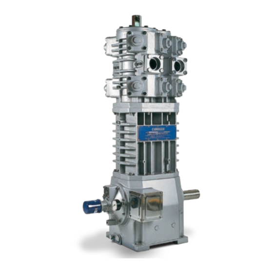
Model FD891
Compressor
Model D791
Model FT891
Compressor
Compressor
Warning: (1) Periodic inspection and maintenance of Corken products is essential. (2) Inspection, maintenance and installation of Corken products must be made only
by experienced, trained and qualified personnel. (3) Maintenance, use and installation of Corken products must comply with Corken instructions, applicable laws and
safety standards. (4) Transfer of toxic, dangerous, flammable or explosive substances using Corken products is at user's risk and equipment should be operated only
by qualified personnel according to applicable laws and safety standards.
Solutions beyond products...

Advertisement

Table of Contents
loading
Need help?

Need help?

Do you have a question about the D Series and is the answer not in the manual?

Questions and answers

Martin Litzenberger
May 16, 2025

Have a customer that has a corkin compressor using on R22 and says the compressor is frosting (Plese see image) What could be the problem?

User image 6827751979dec

Subscribe to Our Youtube Channel

Summary of Contents for Corken D Series

  • Page 1 (3) Maintenance, use and installation of Corken products must comply with Corken instructions, applicable laws and safety standards. (4) Transfer of toxic, dangerous, flammable or explosive substances using Corken products is at user’s risk and equipment should be operated only by qualified personnel according to applicable laws and safety standards.
  • Page 2 Corken One Year Warranty CORKEN warrants that its products will be free from defects in material and workmanship for a period of one year from date of installation, provided that the warranty shall not extend beyond twenty-four (24) months from the date of shipment from CORKEN.
  • Page 3: Table Of Contents

    Table of Contents Chapter 1—Features and Benefits . . . . . . . . . . . . . . . . . . . . . . . . . . . . . . . . . . . . . . . . . . . . . . . . . . . . . . . . . . . . . . . 4 Chapter 2—Installation .
  • Page 4: Chapter 1-Features And Benefits

    Chapter 1—Features and Benefits High-efficiency PEEK valves: Offer quiet operation and increase durability in process gas applications. Ductile iron construction: Maximum thermal shock endurance for cylinder and head. Upper packing (Segmented) Self-lubricating PTFE piston rings: Multiple material options provide the most cost-effective operation of compressors for non-lube service.
  • Page 5: Chapter 2-Installation

    Since Corken’s compressors typically handle toxic and flammable gases, they should be located outdoors in Figure 2.2: Recommended foundation details for Corken compressors. a well ventilated area. To ensure the compressor is accessible from all sides and has unrestricted air flow...
  • Page 6: Liquid Trap

    In most cases, piping should be at least the same interwoven wire designed to remove fine liquid mists. The diameter as the suction nozzle on the compressor. ASME code trap comes standard on Corken’s 107B and 109B mountings. If a restrictive device such as a valve, pressure regulator, or back-check valve is to be installed in the compressor’s...
  • Page 7: Driver Installation And Flywheels

    Considering the relatively NOTE: Never operate a reciprocating compressor without small volume of oil used in Corken compressors, and the a flywheel. Severe torsional imbalances will result causing critical nature of the services where these compressors are used, selecting the appropriate high quality oil is vibration and an unusually high horsepower requirement.
  • Page 8 -58°F (-50°C) Royal Purple Uni-Temp 68 -51°F (-46°C) Consult Corken for oil recommendations in very hot climates—ambient temperatures consistently above 100°F (38°C). Oil type: C=Conventional, S=Synthetic, B=Conventional/Synthetic blend Information available from oil manufacturers at the time of publication. Mobil SHC oils are synthetic oils which require that the crankcase be flushed of residual mineral oil.
  • Page 9 For the purpose of selecting a suitable crankcase oil for Contact Corken if additional assistance is needed when a Corken compressor, normal and heavy service are selecting a crankcase oil.
  • Page 10 Each than the crankcase, so oils used in this service often time the oil is changed, the oil filter (Corken part number have a higher viscosity than the crankcase oil. A viscosity 4225) should also be changed.
  • Page 11: Purging, Padding, Venting, And Draining Of Distance Pieces

    Draining of Distance Pieces gas and local regulations, the purge gas should be vented to a safe release area, flare, compressor’s inlet, With Corken’s compressor the distance piece is key to or treatment facility. leakage control and oil-free compression. It is integral with the crosshead guide.
  • Page 12: Relief Valves

    With parts as necessary. Replace the access cover and fill Corken’s 107 mountings, a relief valve should be fitted the crankcase with the appropriate amount of lubricant in the piping between the compressor discharge and the through the opening behind the nameplate.
  • Page 13: Crankcase Oil Pressure Adjustment

    3 .3 Crankcase Oil Pressure Adjustment Corken’s compressors are equipped with an automatically reversible gear type oil pump. Before starting the compressor, check and fill the crankcase with the proper amount of lubricating oil. Make sure the pumping system is primed and the oil pressure is properly adjusted.
  • Page 14: Startup Check List

    3 .4 Startup Check List After Starting Compressor 1. Verify and note oil pressure. Shut down and NOTE: Before starting the compressor, verify each correct any problems immediately the pressure is item on the list below! not within specification. Failure to do so may result in a costly (or dangerous) 2.
  • Page 15: Chapter 4-Routine Maintenance Chart

    If routine maintenance is performed as listed in chapter assembly is broken, it should be replaced. See parts four, repair service on Corken’s gas compressor is details for valve assemblies in Appendix D for a complete generally limited to replacing valves or piston rings.
  • Page 16: Heads/Cylinder Cap

    5. After the piston is removed, the piston rings and expanders can be easily removed and replaced. 7. Check bolts and valve holddown screws after first Corken recommends replacing expanders whenever week of operation and re-torque if necessary. See rings are replaced. To determine if the piston rings Appendix B for torque values.
  • Page 17: Piston Replacement

    5 .4 Piston Replacement 5 .5 Piston Rod Packing Adjustment 1. To replace the pistons, depressurize the compressor and purge if necessary. On T-Style compressors the piston rod packing should be adjusted or replaced when leakage is prevalent. 2. Remove the cylinder cap and cylinder head (see Adjust packing by tightening packing nuts as shown in section 5.2).
  • Page 18 Workmanship: a. Clean and lightly oil the packing area inside the packing cartridge. Corken’s compressors are a precision piece of equipment with very close tolerances so treat them with care and b. Insert the oil deflector ring through the bottom never hammer parts in or out of the compressor.
  • Page 19 a. Clean the segmented packing cups and the area 7. To remove the lower V-ring packing set, remove the inside the packing barrel. adjusting screw at the bottom of the packing cartridge followed by the washers, packing spring, and old b.
  • Page 20: Bearing Replacement For Crankcase And Connecting Rod

    Insert a female packing ring followed by four 8. Install and tighten holddown screws with Corken’s V-rings and one male packing ring. NOTE: Insert special compressor wrench. packing rings and V-rings one at a time . Refer 9. Install packing barrels. NOTE: Align the pin on one of...
  • Page 21 5 . 7 .2 Replacing Connecting Rod Bearings 3. In order to check the crankshaft endplay, the oil pump must be removed (see section 5.8). Connecting rod bearings are easily replaced by removing the semicircular bearings. Make sure the indentations 4.
  • Page 22: Oil Pump Inspection

    5 .8 Oil Pump Inspection 6. Insert the shaft adapter so it engages the drive pin. If the compressor operates for a prolonged period with 7. Next, insert the spring, spring guide, and oil pump dirty or contaminated crankcase oil, damage to the oil assembly.
  • Page 23: Gasket Sets

    5 .9 Gasket Sets Repair Kit Part Type 3969-X1A D791 (Buna-N and Aluminum) 3969-X1B2 D791 (Neoprene and Steel) ®1 3969-X1D D791 (Viton and Aluminum) ®1 3969-X1D2 D791 (Viton and Steel) ®1 3969-X1E2 D791 (PTFE and Steel) 3969-X2A T791 (Buna-N and Aluminum) 3969-X2A2 T791 (Buna-N and Iron-Compressor Part) 3969-X2B T791 (Neoprene...
  • Page 24: Model Number Identification Code And Available Options

    Appendix A—Model Number Identification Code and Available Options Double Acting, Two Stage, Double Packed (D-Style 791) Model Number Air Cooled Base Model Base X X X X X X X X X X D791 Inlet 2" weld Outlet 2" weld Intercooler connection 2"...
  • Page 25 Appendix A—Model Number Identification Code and Available Options Double Acting, Two Stage, Triple Packed (T-Style 791) Model Number Air Cooled Base Model Base X X X X X X X X X X T791 Inlet 2" weld Double Packed Outlet 2"...
  • Page 26 Appendix A—Model Number Identification Code and Available Options Double Acting, Single Stage, Double Packed (D-Style 891) Model Number Air Cooled Base Model Base X X X X X X X X X X FD891 Inlet 2" ASME Class 300 RF flange Outlet 2"...
  • Page 27 Appendix A—Model Number Identification Code and Available Options Double Acting, Single Stage, Triple Packed (T-Style 891) Model Number Air Cooled Base Model Base X X X X X X X X X X FT891 Inlet 2" ASME Class 300 RF flange Outlet 2"...
  • Page 28: Specifications

    Appendix B—Specifications Equipment Type and Options Double-acting, vertical, reciprocating piston type compressor Two-stage (model 791) and single stage (model 891) designs Double packed rod (models D791, D891, and FD891); triple packed rod (models T791, T891, and FT891) 2" Slip-on weld connections (model 791 only) 2"...
  • Page 29 Appendix B—Specifications Operating Specifications Specification All Models 791 All Models 891 Bore of cylinder, inches (mm) first stage 6 (152.4) 4.5 (113) second stage 3.25 (82.5) — Stroke, inches (mm) 4.0 (101.6) 4.0 (101.6) Piston displacement, cfm (m /hr) minimum @ 400 RPM 51.2 (87.0) 56.6 (96.2) maximum @ 900 RPM...
  • Page 30: Outline Dimensions

    Appendix C—Outline Dimensions Model D791 (Two Stage) Bare Compressor with Flywheel Adjustable head 4 (102) 2-9/16 (65) Suction valve unloaders (optional) 1st stage inlet 2nd stage outlet (2" weld 1st stage inlet 1st stage outlet (2" weld 1/4" NPT drain Compressor wrench Compressor...
  • Page 31 Appendix C—Outline Dimensions Model D891 (Single Stage) Bare with Flywheel (152) (152) Discharge Suction pressure pressure gauge gauge (optional) (optional) Inlet: 2" Class 300 RF Outlet: 2" Class 300 RF Suction valve unloaders (optional) Compressor 43-3/16 wrench Compressor (1,097) wrench Crankcase 35-5/8 oil gauge...
  • Page 32 Appendix C—Outline Dimensions Model T791 (Two Stage) Bare Compressor with Flywheel 4 (10) 2-9/16 (7) Adjustable head Suction valve unloaders (optional) 2nd stage 1st stage outlet (2" inlet (2" 1st stage 1st stage inlet (2" outlet (2" 43-5/8 1/4" NPT 1/4"...
  • Page 33 Appendix C—Outline Dimensions Model FT891 (Single Stage) Bare Compressor with Flywheel (152) (152) Suction Discharge pressure pressure gauge gauge (optional) (optional) Inlet: 2" Outlet: 2" Class 300 RF Class 300 RF Pressurization tube (Spec “F” packing only) Outlet: 2" Suction valve Class 300 RF unloaders (optional)
  • Page 34: Parts Details

    Appendix D—Head and Valve Holddown Assembly Details for All Models 791 Head First Stage Holddown Assembly (6" Cylinder) First Stage Holddown Assembly (6" Cylinder) Suction (Standard) Suction (Standard) Spec 4P and 4PL Spec 9P and 9PL Discharge (All Specs) gure A CAUTION: Always relieve pressure in the unit before attempting any repairs.
  • Page 35 Appendix D—Head and Valve Holddown Assembly Details for All Models 791 First Stage Valve Assembly (6" Cylinder) Second Stage Valve Assembly (3-1/4" Cylinder) Suction Discharge Suction Discharge Part No . Description Qty . Part No . Description Qty . No . No .
  • Page 36 Appendix D—Head & Valve Assembly Parts Details for All Flanged Models 891 Head Valve Holddown Assembly (4-1/2" Cylinder) Suction Suction Discharge (Specs 4P, 4PL) (Specs 9P, 9PL) (All Specs) Figure B Unloader Assembly Part Details Part Numbers Apply Loctite #290 when assembling 1910 2619-X...
  • Page 37 Appendix D—Piston Assembly Details for All Models 791 and Flange 891 Piston Assembly Bill of Materials Part No . Ref . All Models 791 All Models 791 All Models Description No . 1st Stage 2nd Stage 891 3925-X1 Piston 3879-X1 (6") 3884-X1 (3-1/4")
  • Page 38 Appendix E—D791 and D891 Packing Assembly Details Specification “J” Specification “K” Radial Radial Tangent Tangent Radial Radial Tangent Tangent Upper Upper Segmented Segmented Packing Packing Radial Radial Tangent Tangent Tangent Tangent Tangent Tangent V-ring Packing Direction Lower Packing Lower Packing Specification Specification “J”...
  • Page 39 Appendix E—D791 and D891 Packing Assembly Details Packing Assembly Bill of Materials Specification “R” Qty . per Part No . Description No . Compressor Packing barrel (3-1/4" cylinder) 3886 (791 second stage) Packing barrel (6" cylinder) (791 3887 first stage) Packing barrel (4-1/2"...
  • Page 40 Appendix D—Packing Assembly Details for Models T791 and FT891 Specification “G” Specification “H” Radial Radial Tangent Tangent Radial Radial Tangent Tangent Upper Upper Radial Radial Segmented Segmented Tangent Tangent Packing Packing Tangent Tangent Tangent Tangent V-ring Packing Direction Middle Packing Middle Packing Speci cation Speci cation...
  • Page 41 Appendix D—Packing Assembly Details for Models T791 and FT891 Packing Assembly Bill of Materials Specification “F” Qty . per Part No . Description No . Compressor 3886 Packing barrel (3-1/4", 791 2nd stage) 3887 Packing barrel (6", 791 1st stage) 3926 Packing barrel (4-1/2", 891 only) 2-228__...
  • Page 42 Appendix D—Crosshead Guide Parts Details for Model D791 Crosshead Guide Bill of Materials Qty . per Part No . Description No . Compressor 3866 Cylinder Valve openings 3442 Pipe plug (1/4" NPT) 1st stage inlet 2-258__ O-ring for cylinder (1st stage) 2-236__ O-ring for cylinder (2nd stage) Bolt (1/2"–13 x 1-3/4"...
  • Page 43 Appendix D—Crosshead Guide Parts Details for Model T791 Crosshead Guide Bill of Materials Qty . per Valve openings Part No . Description No . Compressor 1st stage 7 6, 6A 3866 Cylinder inlet Pipe plug (1/4" NPT, Specs G 3442 16/14 and H/F) 2-258__...
  • Page 44 Appendix D—Crosshead Guide Parts Details for Model FD891 Crosshead Guide Bill of Materials Qty . per Part No . Description No . Compressor 4851 Cylinder (Class 300 RF flange) 3442 Pipe plug (1/4” NPT) 10/8 Valve openings 2-246__ O-ring for cylinder 2405-1 Crosshead guide Inlet...
  • Page 45 Appendix D—Crosshead Guide Parts Details for Model FT891 Crosshead Guide Bill of Materials Qty . per Part No . Description Valve openings No . Compressor 4851 Cylinder (Class 300 RF flange) Inlet 3442 Pipe plug (1/4" NPT) 2-246__ O-ring for cylinder Outlet 1716-4X Crosshead guide...
  • Page 46 Appendix D—Connecting Rod and Crosshead Assemblies Parts Details for All Models Connecting Rod—Bill of Materials Qty . per Part No . Description No . Compressor Crosshead assembly 3544-X3 (D791, FD891) Crosshead assembly 3544-X9 (T791, FT891) 3590 Retainer ring 3540 Wrist pin 3541-X Wrist pin bushing 1726...
  • Page 47 Appendix D—Flywheel Assembly Parts Details for All Models Flywheel—Bill of Materials Back Side Part No . Description Qty . No . Flywheel (5V21.2" O.D., 3852 5 V-groove) Hub with three bolts and H J-2.125 lockwashers 3503 Assembly Number Assembly Name Flywheel assembly 3852-X (flywheel, hub, key, and three bolts)
  • Page 48 Appendix D—Crankcase Assembly Parts Details for All Models 64,64A 23 24 55 NOTE: Includes all parts within this bracket except part numbers 51 and 52. Back Side of Bearing Carrier Back Side of Oil Filter Adapter Oil Passage Hole Back side of adapter shows NOTE: Oil passage hole must proper orientation of cover and line up with hole in gasket!
  • Page 49 Appendix D—Crankcase Assembly Parts Details for All Models Crankcase Assembly Bill of Materials Part No . Description Qty . Part No . Description Qty . No . No . 1737 Bearing cone 1291 Adjusting screw locknut 3638-1 Spacer, without lubricator 1292 Relief valve spring 1284...
  • Page 50: Troubleshooting

    Appendix E—Troubleshooting In most cases, problems with a Corken compressor can be solved quite simply. This chart lists some of the more frequent problems that occur with reciprocating compressors along with a list of possible causes. If there is a problem not listed below, or if the source of the problem cannot be identified, consult the factory.
  • Page 51: Extended Storage Procedures

    Appendix F—Extended Storage Procedures Performing a few simple procedures greatly minimizes the risk of the compressor becoming corroded and damaged. The following precautions will protect it from corrosion during storage: 1. Drain the oil from the crankcase and refill it with a rust inhibiting oil.
  • Page 52 Solutions beyond products... 9201 North I-35 Service Road, Oklahoma City, OK. 73131 U.S.A. Phone (405) 946-5576 • Fax (405) 948-7343 Website: www.corken.com E-mail: cocsalesdept@idexcorp.com @CorkenInc Printed in the U.S.A. September 2022...

This manual is also suitable for:

T seriesD791Fd891Ft891

Table of Contents