Table of Contents
Advertisement
Quick Links
Installation, Operation
& Maintenance Manual
D and T-Style Double-Acting Gas Compressors
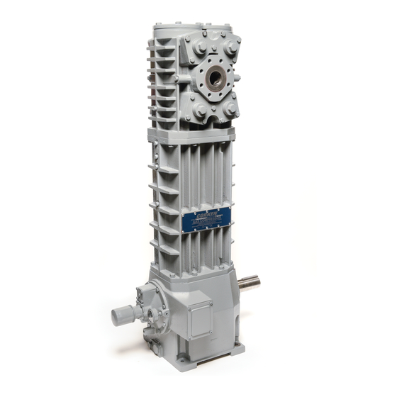
Model D891
Compressor Package
Warning: (1) Periodic inspection and maintenance of Corken products is essential. (2) Inspection, maintenance and installation of Corken products must be made
only by experienced, trained and qualified personnel. (3) Maintenance, use and installation of Corken products must comply with Corken instructions, applicable laws
and safety standards (such as NFPA Pamphlet 58 for LP-Gas and ANSI K61.1-1972 for Anhydrous Ammonia). (4) Transfer of toxic, dangerous, flammable or explosive
substances using Corken products is at user's risk and equipment should be operated only by qualified personnel according to applicable laws and safety standards.
Models D791, T791, D891 and T891
Model T891
Compressor
IJ110E
Advertisement
Table of Contents

Related Manuals for Corken D791


Summary of Contents for Corken D791
- Page 1 (such as NFPA Pamphlet 58 for LP-Gas and ANSI K61.1-1972 for Anhydrous Ammonia). (4) Transfer of toxic, dangerous, flammable or explosive substances using Corken products is at user’s risk and equipment should be operated only by qualified personnel according to applicable laws and safety standards.
- Page 2 Corken One Year Limited Warranty Corken, Inc. warrants that its products will be free from defects in material and workmanship for a period of 12 months following date of purchase from Corken. Corken products which fail within the warranty period due to defects in material or workmanship will be repaired or replaced at Corken’s option, when returned freight prepaid to: Corken,...
-
Page 3: Table Of Contents
CHAPTER 2—STARTING UP YOUR CORKEN COMPRESSOR ........ -
Page 4: Features And Benefits
Features and Benefits High-efficiency valves: Corken valves offer quiet operation and high durability in oil-free gas applications. Ductile iron construction: All cylinders and heads are ductile iron for maximum thermal shock endurance. Upper packing (Segmented) Self-lubricating PTFE piston rings: Corken provides a variety of state-of-the-art piston ring designs to provide the most cost-effective operation of compressors for non-lube service. -
Page 5: Chapter 1-Installing Your Corken Compressor
Corken. Check local safety regulations and building codes to assure installation will meet local safety standards. Corken compressors handling toxic or flammable gases such as LPG/NH should be located outdoors in 3/4″... -
Page 6: Liquid Trap
For vapor recovery applications, be certain to install Corken’s liquid trap provides the most thorough liquid a check valve on vapor lines discharging to the liquid separation (see figure 1.4) and is ASME code stamped. space of the tank. It contains two level switches, one for alarm and one for shutdown. -
Page 7: Purging, Padding, Venting And Draining Of Distance Pieces
The key to leakage control and oil-free operation of also the side with the spring. Corken compressors is the distance piece. The distance piece is integral with the crosshead guide and forms Moisture, oil, or condensate can be removed from the the upper portion of it. -
Page 8: Relief Valves
Corken offers Purge Kits which include the necessary devices should be selected to meet local code regulator, valves, fittings, etc. Consult the factory or see requirements. Shutdown/alarm devices typically used on Important Instruction, item number IE210, for details. Corken compressors are as follows: Padding (Buffering): Low Oil Pressure Switch—shuts down the unit if... -
Page 9: Chapter 2-Starting Up Your Corken Compressor
(see figure 2.2A). These bolts should be tightened in an even and progressive manner to the Your Corken compressor is equipped with an automatically specified torque values listed below. There must be a reversible gear type oil pump. It is essential to ensure... -
Page 10: Startup Check List
The oil pressure should be about 20 psi (1.4 bars) minimum 10. Rotate unit by hand and make certain there is no for normal service. If the compressor discharge pressure wobble or play. is above 200 psi (14.8 bars), the oil pressure must be 11. -
Page 11: Chapter 3-Routine Maintenance Chart
Chapter 3—Routine Maintenance Chart Item to Check Daily Weekly Monthly Yearly Months Crankcase oil pressure Compressor discharge pressure Overall visual check Crankcase oil level Drain liquid from accumulation points Drain distance pieces Clean cooling surfaces on compressor and intercooler (if any) Lubricator supply tank level (if any) Check belts for correct tension Inspect valve assemblies... -
Page 12: Chapter 4-Routine Service And Repair Procedures
Disassembly If routine maintenance is performed as listed in chapter 3, repair service on your Corken gas compressor is 1. Unscrew the valve cap and remove the O-ring. generally limited to replacing valves or piston rings. When it comes time to order replacement parts, be sure 2. -
Page 13: Heads
15. Replace the previously removed valves. Best results will be obtained if new valve gaskets are used. 5. Piston rings and expanders may then be easily removed and replaced. Corken recommends replacing 16. Follow standard startup procedures. expanders whenever rings are replaced. To determine if... -
Page 14: Piston Rod Packing Adjustment
4.6.1 Model D791 and D891 Compressors (D-Style) a hone to smooth the cylinder bore and then polish it On Models D791 and D891, there is one set of V-ring to the value shown in Appendix B. If more than .005 of... - Page 15 4. Remove the four socket head screws that hold the a. Clean the segmented packing cups and the area packing box cartridge to the barrel. inside the packing barrel. 5. Remove segmented packing and cups from barrel. b. Insert the segmented packing cups, segmented packing pairs and backup rings one at a time in 6.
- Page 16 Assembly of Packing (T-Style) e. Lastly, push in on the washer and insert the third retainer ring. 1. Replace packing as required. The segmented packing and cups are located in the packing barrel while the f. Install two O-rings on the packing box cartridge as V-ring packing is located in the packing box cartridge.
-
Page 17: Bearing Replacement For Crankcase And Connecting Rod
4.7 Bearing Replacement for 4. Make sure the lubrication hole in the bushing matches the oil passage in the connecting rod. If the holes do Crankcase and Connecting Rod not align, drill out the bushing through the connecting rod lubricant passage with a long drill. Bore the wrist 1. -
Page 18: Oil Pump Inspection
4.7.3 Replacing Crankcase Roller Bearings add more shims, but make sure not to over shim. (Appendix B lists the proper crankshaft endplay). When To inspect the roller bearings, remove the flywheel from the crankshaft can be rotated freely by hand with the crankshaft and then remove the bearing carrier and proper endplay, the rest of the compressor may be crankshaft from the crankcase. -
Page 19: Chapter 5-Extended Storage Procedures
Following a few simple procedures will greatly minimize the slot in the shaft adapter. the risk of the unit becoming corroded and damaged. Corken recommends the following precautions to protect 8. Install the pump cover so the pin on the case the compressor during storage: is in the opening on the oil pump assembly as shown in figure 4.8. -
Page 20: Vertical Double-Acting Model Number Identification Code
Standard Coating *Must select Protective Coating Option "W" when selecting valve option "4C", or "9C" for the D791 (a) 1 = up to 200 psi or 2 = above 200 psi (discharge pressure) (b) 1 = 30 to 70 psi or 2 = 71 to 150 psi or 3 = 151 to 500 psi (discharge pressure) NA = Not Available NC = No Charge Option Registered trademarks of the DuPont company. - Page 21 Appendix A—Industrial Vertical Double Acting Model Number Identification Code (T-Style) MODEL NUMBER BASE MODEL NUMBER T791 T891 BASE X X X X X X X X X X Inlet 2" weld 2" weld Outlet 2" weld 2" weld Intercooler connection 2"...
-
Page 22: Vertical Double-Acting Specifications
Appendix B—Vertical Double-Acting Specifications Equipment Type & Options Double-acting, vertical, reciprocating piston type compressor Two-stage configuration (model 791 only) Double packed rod (models D791 & D891); triple packed rod (models T791 & T891) Slip-on weld connections Features & Benefits Self-lubricating piston rings:... - Page 23 Appendix B—Vertical Double-Acting Specifications Specifications and Performance Specification D791 D891 T791 T891 Bore of cylinder, inches (mm) first stage 6 (152.4) 4.5 (113) 6 (152.4) 4.5 (113) second stage 3.25 (82.5) — 3.25 (82.5) — Stroke, inches (mm) 4.0 (101.6) 4.0 (101.6)
-
Page 24: Outline Dimensions
Appendix C—Outline Dimensions Model D791 (Two Stage) Bare Compressor with Flywheel Adjustable head 4 (10.2) 2-9/16 (6.5) Suction valve unloaders (optional) 1st stage inlet 2nd stage outlet (2" weld 1st stage inlet 1st stage (2" weld flange) flange) (2" weld flange) outlet (2"... - Page 25 Appendix C—Outline Dimensions Model D891 (Single Stage) Bare with Flywheel Suction 5-1/2" 5-1/2" valve unloaders (13.9) (13.9) (optional) Inlet Inlet (2" weld Outlet (2" weld flange) pressure flange) gauge Inlet Outlet pressure (2" weld guage flange) 1/4" NPT drain 43-1/4" Crankcase heater (109.9) (optional)
- Page 26 Appendix C—Outline Dimensions Model D891 (Single Stage) with 103 Mounting...
- Page 27 Appendix C—Outline Dimensions Model D891 (Single Stage) with 107B Mounting...
- Page 28 Appendix C—Outline Dimensions Model D891 (Single Stage) with 109B Mounting...
- Page 29 Appendix C—Outline Dimensions Model T791 (Two Stage) Bare Compressor with Flywheel 4 (10) 2-9/16 (7) Adjustable head Suction valve unloaders (optional) 2nd stage 1st stage outlet (2″ inlet (2″ 1st stage weld flange) weld flange) 1st stage inlet (2″ outlet (2″ weld flange) weld flange) 1/4″...
- Page 30 Appendix C—Outline Dimensions Model T891 (Single Stage) Bare Compressor with Flywheel Suction valve 5-7/16 5-7/16 unloaders (13.9) (13.9) (optional) Inlet Inlet Outlet (2″ (2″ weld flange) (2″ weld flange) weld flange) 1/4″ upper distance piece 1/4″ NPT 51-1/4 lower (130.1) distance piece 5-5/8...
- Page 31 Appendix C—Outline Dimensions Model T891 (Single Stage) with 103 Mounting...
-
Page 32: Troubleshooting
Appendix D—Troubleshooting In most cases, problems with your Corken gas compressor compressors along with a list of possible causes. If you can be solved quite simply. This chart lists some of the are having a problem which is not listed, or if you cannot more frequent problems that occur with reciprocating find the source of the problem, consult the factory. -
Page 34: Assembly Details
Appendix E—D791 and T791 Head and Valve Holddown Assembly Details Head First Stage Holddown Assembly (6") First Stage Holddown Assembly (6") Suction with Unloader Suction (Standard) Discharge gure A CAUTION: Always relieve pressure in the unit before attempting any repairs. - Page 35 Appendix E—D791 and T791 Head and Valve Holddown Assembly Details First Stage Valve Assembly (6") Second Stage Valve Assembly (3-1/4") Suction Discharge Suction Discharge Part No. Description Part No. Description 3665 Adjusting screw nut 3690 Spring 2-127 O-ring 3689-X Unloader assembly (3-1/4")
- Page 36 Appendix E—D891 and T891 Head and Valve Holddown Assembly Details Head Holddown Assembly (4-1/2") Holddown Assembly (4-1/2") Suction with Unloader Suction (Standard) Discharge gure A CAUTION: Always relieve pressure in the unit before attempting any repairs. Unloader Assembly Part Details Valve Assemblies (4-1/2") Suction Valve Discharge Valve...
- Page 37 Appendix E—D891 and T891 Head and Valve Holddown Assembly Details Compressor Head and Valve Bill of Materials Part No. Description Part No. Description 3923 Cylinder cap 2714-1 Valve cap 3924 Cylinder head (4-1/2") 3569 Valve cage 2-246 O-ring 3733-X Discharge valve assembly (4-1/2") Bolt (1/2 - 13 x 1-1/2"...
- Page 38 Appendix E—D791, T791, D891 and T891 Piston Assembly Details Piston Assembly Bill of Materials Part No. Ref. D/T791 2nd Description D/T791 1st Stage D/T891 Stage 3879-X1 (6") 3925-X1 (4-1/2") 3884-X1 (3-1/4") Screw, orlo gr. 8 7002-025-TP100A 7002-010-TP100A 7002-025-TP100A (torque to 8 ft•lbs)
- Page 39 Appendix E—D791, T791, D891 and T891 Connecting Rod and Crosshead Assembly Details Connecting Rod and Crosshead Assembly Bill of Materials Part No. Description 3544-X3 Crosshead assembly (D791, D891) 3544-X9 Crosshead assembly (T791, T891) Crosshead assembly—coated piston rod 3544-X10 (T791, T891)
- Page 40 Appendix E—D791 and D891 Packing Assembly Details Specification “J” Specification “K” Radial Radial Tangent Tangent Radial Radial Tangent Tangent Upper Upper Segmented Segmented Packing Packing Radial Radial Tangent Tangent Tangent Tangent Tangent Tangent V-ring Packing Direction Lower Packing Lower Packing...
- Page 41 Appendix E—D791 and D891 Packing Assembly Details Packing Assembly Bill of Materials Specification “R” Part No. Description 3886 Packing barrel (3-1/4")(791 second stage) 3887 Packing barrel (6")(791 first stage) 3926 Packing barrel (4-1/2")(891 only) 3906 Crush gasket Packing cup (Not included in 3810-X1...
- Page 42 Appendix E—T791 and T891 Packing Assembly Details Specification “G” Specification “H” Radial Radial Tangent Tangent Radial Radial Tangent Tangent Upper Upper Radial Radial Segmented Segmented Tangent Tangent Packing Packing Tangent Tangent Tangent Tangent V-ring Packing Direction Middle Packing Middle Packing Specification Specification Middle...
- Page 43 Appendix E—T791 and T891 Packing Assembly Details Packing Assembly Bill of Materials Specification “F” Part No. Description 3886 Packing barrel (3-1/4")(791 second stage) 3887 Packing barrel (6")(791 first stage) 3926 Packing barrel (4-1/2")(891 only) 3906 Crush gasket Packing cup (Not included in 3810-X1 3817 packing set) a,c,d...
- Page 44 Appendix E—D791 Crosshead Guide Assembly Details Crosshead Guide Bill of Materials Part No. Description 3866 Cylinder 3442 Pipe plug (1/4" NPT) 1054 Drain valve (lubricated models) 1071 Nipple (1/4" x close) 2-258_ a O-ring for cylinder (1st stage) 5-1. 2-236_ a O-ring for cylinder (2nd stage) Bolt (1/2"...
- Page 45 Appendix E—D891 Crosshead Guide Assembly Details Crosshead Guide Bill of Materials Part No. Description 3922 Cylinder 3442 Pipe plug (1/4" NPT) 1054 Drain valve (lubricated models) 1071 Nipple (1/4" x close) 2-246_ a O-ring for cylinder Bolt (1/2"- 13 x 1-3/4" hex head 7001-050NC175A gr 5) 3793-2S...
- Page 46 Appendix E—T791 Crosshead Guide Assembly Details Crosshead Guide Bill of Materials Part No. Description 3866 Cylinder 3442 Pipe plug (1/4" NPT) 1054 Drain valve (lubricated models) 1071 Nipple (1/4" x close) 2-258_ a O-ring for cylinder (1st stage) 5-1. 2-236_ a O-ring for cylinder (2nd stage) Bolt (1/2"...
- Page 47 Appendix E—T891 Crosshead Guide Assembly Details Crosshead Guide Bill of Materials Part No. Description 3922 Cylinder 3442 Pipe plug (1/4" NPT) 1054 Drain valve (lubricated models) 1071 Nipple (1/4" x close) 2-246_ a O-ring for cylinder Bolt (1/2" 13 x 1-3/4" hex head 7001-050NC175A gr 5) 3793-2S...
- Page 48 Appendix E—Crankcase Assembly Details 63 (Pipe plug on under side of crankcase is not shown) Inside of Bearing Carrier Oil Passage Hole Important! Line up hole in gasket with oil passage hole. Pump Cover Oil/Filter Adapter Pumpside of adapter shown for (Includes all parts shown proper orientation of cover and except #52 and #53)
- Page 49 Appendix E—Crankcase Assembly Details Crankcase Assembly Bill of Materials Part No. Description Part No. Description 1737 Bearing cone 3219 Pump shaft adapter 2-112_ c 3638 Spacer O-ring 2805-X a 3635 Drive sprocket Pump shaft bushing 1284 Crankshaft orifice 1629 Pipe plug (1/16 NPT fl. seal) 2135 Drive pin 1736...
- Page 50 Appendix E—Flywheel Assembly Details Back Side Front Side Flywheel Assembly Bill of Materials Assembly Assembly Name Number Flywheel assembly (flywheel, hub, 3852-X and three bolts) 3852 Flywheel: 21.2" O.D., 5 groove Hub with three bolts and H J-2.125 lockwashers...
- Page 52 Solutions beyond products... CORKEN, INC. • A Unit of IDEX Corporation 3805 NW 36th Street, Oklahoma City, OK 73112 Phone (405) 946-5576 • Fax (405) 948-7343 Visit our website at www.corken.com or e-mail us at cocsalesdept@idexcorp.com @CorkenInc Printed in the U.S.A.
Need help?
Do you have a question about the D791 and is the answer not in the manual?
Questions and answers