Table of Contents
Advertisement
Installation, Operation
& Maintenance Manual
Liquid Transfer-Vapor Recovery Compressors
Warning: (1) Periodic inspection and maintenance of Corken products is essential. (2) Inspection, maintenance and installation of Corken
products must be made only by experienced, trained and qualified personnel. (3) Maintenance, use and installation of Corken products
must comply with Corken instructions, applicable laws and safety standards (such as NFPA Pamphlet 58 for LP-Gas and ANSI K61.1-1972
for Anhydrous Ammonia). (4) Transfer of toxic, dangerous, flammable or explosive substances using Corken products is at user's risk and
equipment should be operated only by qualified personnel according to applicable laws and safety standards.
IE101H
Advertisement
Table of Contents

Related Manuals for Corken F291


Summary of Contents for Corken F291
- Page 1 (3) Maintenance, use and installation of Corken products must comply with Corken instructions, applicable laws and safety standards (such as NFPA Pamphlet 58 for LP-Gas and ANSI K61.1-1972 for Anhydrous Ammonia). (4) Transfer of toxic, dangerous, flammable or explosive substances using Corken products is at user’s risk and...
- Page 2 Corken One Year Limited Warranty Corken, Inc. warrants that its products will be free from defects in material and workmanship for a period of 12 months following date of purchase from Corken. Corken products which fail within the warranty period due to defects in material or workmanship will be repaired or replaced at Corken’s option, when returned freight prepaid to Corken,...
-
Page 3: Table Of Contents
ChApter 3—stArting up YOur COrKen COmpressOr ........pAge... -
Page 4: Chapter 1-Introduction
Compressors are available in either threaded NPT, ANSI, or dIN flanged connections. high-efficiency valves: Corken valves offer quiet operation and high durability in oil-free gas applications. Specially designed suction valves which tolerate small amounts of condensate are used in liquid transfer- vapor recovery compressors. -
Page 5: Liquid Transfer By Vapor Differential Pressure
After the liquid has been transferred, the four-way control valve (or alternate valve manifolding) is reversed so that the vapors are Corken LPG/NH compressors are designed to drawn from the tank just unloaded and discharged into transfer liquefied gases such as butane/propane the receiving tank. -
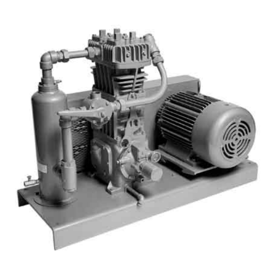
Page 6: Compressor Construction Features
Construction features Figure 1.3A: 107-Style Compressor Mounting The Corken liquid transfer-vapor recovery compressor Corken gas compressors are mounted on oil lubricated is a vertical single-stage, single-acting reciprocating crankcases that remain at atmospheric pressure. compressor designed to handle flammable gases like LPG Crankshafts are supported by heavy-duty roller bearings and toxic gases such as ammonia. - Page 7 PTFE V-rings sandwiched between a male and female packing ring and held in place by a spring (see figure 1.3C). The typical Corken compressor valve consists of a seat, Suction Valve Spec 3 bumper, one or more spring/s and one or more valve/s Gasket discs or plates as shown in figure 1.3d.
-
Page 8: Chapter 2-Installing Your Corken Compressor
On ALL mOdeLs as corrosive environments, arctic conditions, etc., consult 8” min. Corken. Check local safety regulations and building codes 1/2” “J” bOLts to assure installation will meet local safety standards. 12” LOng Corken compressors handling toxic or flammable gases such... - Page 9 Care must be taken if a restrictive device such as a valve, A tank car unloading riser should have two liquid hoses pressure regulator, or back-check valve is to be installed connected to the car liquid valves. If only one liquid hose in the compressor’s suction line.
-
Page 10: Liquid Traps
On liquefied gas applications, a liquid trap must be used to prevent the entry of liquid into the compressor. Corken offers three types of liquid traps for removal of entrained liquids. The simplest is a mechanical float trap (see figure 2.4A). As the liquid enters the trap the gas velocity is greatly reduced, which allows the entrained liquid to drop out. - Page 11 (see figure 2.4b). The automatic trap replaces the float with electrical float switches. If the liquid level should rise too of other than Corken manufacture, make sure it is high, the level switch will open and disconnect the power of adequate size to thoroughly remove any liquid entrained in the suction stream.
-
Page 12: Driver Installation / Flywheels
These gases react with the detergent and cause the crankcase oil to become Corken compressors are may be mounted on trucks to corrosive and contaminated. Figures 2.6A and 2.6b show perform liquid transfer operations as described in section recommended oil viscosities and crankcase capacities. -
Page 13: Shutdown/Alarm Devices
All electronic devices Figure 2.8B: U-joint Drive for Compressor should be selected to meet local code requirements. Shutdown/alarm devices typically used on Corken compressors are: Low Oil Pressure Switch: Shuts down the unit if crankcase oil pressure falls below 12 psi due to oil pump failure or low oil level in crankcase. -
Page 14: Chapter 3-Starting Up Your Corken Compressor
These bolts should be tightened in an even and progressive manner until torqued as specified Corken compressor models 291 through 891 are below. There must be a gap between the bushing flange equipped with an automatically reversible gear type oil and the flywheel when installation is complete. -
Page 15: Startup Checklist
remove the pressure gauge. restart the compressor 8. Check V-belt tension and alignment. Check drive and run it until oil comes out of the pressure gauge alignment on direct drive units. opening. reinstall the gauge. 9. rotate unit by hand. Check flywheel for wobble or play. The oil pressure should be about 20 psi (1.4 bars) minimum 10. -
Page 16: Chapter 4-Routine Maintenance Chart
Chapter 4—routine maintenance Chart item to Check daily Weekly monthly Yearly months Crankcase oil pressure Compressor discharge pressure Overall visual check Crankcase oil level drain liquid from accumulation points drain distance pieces Clean cooling surfaces on compressor and intercooler (if any) Lubricator supply tank level (if any) Check belts for correct tension Inspect valve assemblies... -
Page 17: Chapter 5-Routine Service And Repair Procedures
1. Valve cap If routine maintenance is performed as listed in chapter 2. Valve cap O-ring 4, repair service on your Corken gas compressor is generally limited to replacing valves or piston rings. 3. Holddown screw When it comes time to order replacement parts, be sure to consult the part details appendix in the back of this 4. - Page 18 disassembly the holddown screw has been secured with an impact wrench at the factory, you will probably need to wait to 1. unscrew the valve cap and remove O-ring. remove the holddown screw until after the cover plate has been removed. At this point in time, the holddown 2.
-
Page 19: Head
5.3A by pinching two loose bolts together. 4. Piston rings and expanders may then be easily removed and replaced. Corken recommends replacing expanders whenever rings are replaced. To determine if rings should be replaced, measure the radial thickness and compare it to the chart in Appendix C. -
Page 20: Piston Rod Packing Adjustment
Workmanship: your Corken compressor is a precision piece of equipment with very close tolerances. Treat it as such. Never beat on it to get parts in or out. - Page 21 3. Loosen adjusting screw and remove retainer ring, 2. Slightly thread in adjusting screw. washers, packing spring and old packing from 3. Install packing rings including male and female crosshead guide. packing rings, one at a time, as shown in Appendix H Assembly of packing or I.
-
Page 22: Bearing Replacement For Crankcase And Connecting Rod
4. Insert a packing washer, packing spring and another removing the head, cylinder, piston, crosshead guide packing washer. and crosshead assembly. 5. Push down on washer and insert retainer ring. 2. drain the crankcase and remove the inspection plate(s). 6. Oil piston rod and replace cartridge O-ring. 3. -
Page 23: Oil Pump Inspection
Figure 5.6.3A: Bearing Carrier Replacement 5.8 Oil pump inspection present, the roller bearings should be replaced. When replacing roller bearings, always replace the entire bearing, not just the cup or the cone. If the compressor operates for a prolonged period with dirty or contaminated crankcase oil, damage to the oil 1. -
Page 24: Servicing The Four-Way Valve
1. remove the hex nut, indicator plate and handle from the rotor shaft. unlike older units, new Corken compressors mounted in 2. remove the four hex head bolts and the cap from the the –107 arrangement are being supplied with a non-lube body. -
Page 25: Chapter 6-Extended Storage Procedures
5.9d. Following a few simple procedures will greatly minimize the risk of the unit becoming corroded and damaged. Corken recommends the following precautions to protect the compressor during storage: 1. -
Page 26: Repair Kits And Gasket Sets
Appendix A—repair Kits and gasket sets Compressor repair Kits part number 3549-x1 3550-x1 3551-x1 3552-x1 3552-x2 5578-x2A model number 90J3, 91J3 290K3, 291m3 490K3, 491m3 690K3, 690p3 690m3, 691m3 891m3 Suction valve assembly 3483-1X 3483-1X (2) 2532-1X 3948-X (2) 3948-X (2) 3732-X discharge valve assembly 3485-X... -
Page 27: A. Repair Kits And Gasket Sets
Appendix A—repair Kits and gasket sets (continued) model 491 gasket set (1481-x6A) model 691 gasket set (1744-x3A) part part description Quantity description Quantity number number 1418 Valve gasket, aluminum 1760 Inspection plate gasket 1480 Center headbolt gasket - steel 2-031A O-ring, buna-N 1488 Inspection plate gasket... -
Page 28: Model Number And Mounting Identification Code
Inlet 3/4" NPT 3/4" NPT 1-1/4" NPT 2" NPT Outlet 3/4" NPT 3/4" NPT 1-1/4" NPT 1-1/2" NPT base Model F291 F491 F691 Inlet 3/4" ANSI 3/4" ANSI 1-1/4" ANSI 2" ANSI Outlet 3/4" ANSI 3/4" ANSI 1-1/4" ANSI 2"... - Page 29 Appendix b vertical double-Acting model number identification Code model number base Model Number d891 base x x x x x x x x x x Inlet Connection 2" Weld Outlet Connection 2" Weld Ship Weight (lb) Packing Packing arranged for padding of distance piece Standard Arrangement Crankcase...
-
Page 30: Operating And Material Specifications, Bolt Torque Values, Clearance And Dimensions
Appendix C—vertical single-Acting specifications models 91–691 equipment type & Options Applications Single-acting, vertical, reciprocating piston type vapor compressor bulk transfer Single packed rod Vapor recovery Tank evacuation NPT or 300# ANSI connections Gas scavenging features and benefits Self-lubricating piston rings: Non-lubricated operation to minimize oil in gas NPT or 300# ANSI connections: Versatility for your application... - Page 31 Appendix C—vertical single-Acting specifications models 91–691 material specifications part model standard material Optional material Head, Cylinder ductile iron ASTM A536 None Crosshead guide crankcase, flywheel, Gray iron ASTM A48, Class 30 None bearing carrier Flange ductile iron ASTM A536 Steel weld flange 91, 291 17-4 PH stainless steel Valve seat &...
- Page 32 Appendix C—vertical single-Acting specifications bolt torque values valve Crank- valve hold- piston valve Cap valve Cap Conn. case Cyl. to Cover down Lock piston torque torque bearing bearing inspec x-head head plate screw screw bolt Carrier Cover plate guide (1.2) bolt torque torque...
- Page 33 Appendix C—vertical single-Acting specifications Clearances and dimensions 691/d891 (M crankcase) **Clearance: “X” piston figure 5.4A & 0.020 0.020 0.000/0.020 0.000/0.015 5.4b 0.044 0.044 0.024/0.044 0.012/0.027 Clearance: connecting rod bearing to 0.0005 0.0005 0.0005 0.0019 crankshaft journal 0.0025 0.0025 0.0025 0.0035 Clearance: wrist pin to wrist pin 0.0009 0.0009...
- Page 34 Appendix C—vertical double-Acting specifications model d891 equipment type & Options Applications double-acting, vertical, reciprocating piston type vapor compressor bulk transfer Truck, tank, railcar, barge unloading double packed rod LTVr and scavenger applications Slip-on weld connections Emergency evacuation features and benefits Self-lubricating piston rings: Non-lubricated operation to minimize oil in gas Multiple materials and configurations: Versatility for your application...
- Page 35 Appendix C—vertical double-Acting specifications model d891 material specifications part standard material Optional material Head, cylinder ductile iron ASTM A536 distance piece Crosshead guide Gray iron ASTM A48, Class 30 Crankcase, flywheel bearing carrier Flange ASTM A36 carbon steel Valve seat, bumper 17-7 PH stainless steel Valve plate 410 stainless steel...
-
Page 36: Mounting Selections
Appendix d—Compressor selection Compressor mounting selections Inlet pressure gauge Outlet pressure gauge standard 107 items Steel baseplate V-belt drive Adjustable driver slide base Enclosed steel belt guard Inlet and outlet pressure gauges NEMA 7 liquid level 40 Micron strainer switch Non-lube 4-way valve (107A only) Interconnecting piping... -
Page 37: Butane
Appendix d—Compressor selection butane Compressor selection table driver horsepower Liquid Liquid transfer transfer & Without residual residual driver sheave size vapor vapor Capacity displacement Compressor pitch diameter (inches) recovery recovery piping size service model 1,750 rpm 1,450 rpm 100°f 80°f 100°f 80°f vapor Liquid... -
Page 38: Propane
Appendix d—Compressor selection propane Compressor selection table driver horsepower Liquid Liquid transfer transfer & Without residual residual driver sheave size vapor vapor Capacity displacement Compressor pitch diameter (inches) recovery recovery piping size service model 1,750 rpm 1,450 rpm 100°f 80°f 100°f 80°f vapor Liquid... -
Page 39: Ammonia
Appendix d—Compressor selection Ammonia Compressor selection table driver horsepower Liquid Liquid transfer transfer & Without residual residual driver sheave size vapor vapor Capacity displacement Compressor pitch diameter (inches) recovery recovery piping size service model 1,750 rpm 1,450 rpm 100°f 80°f 100°f 80°f vapor Liquid... -
Page 40: Outline Dimensions
— 19-1/8 ANSI (16.1) (17.6) (9.7) (49.5) (5.4) (1.27) (48.5) Optional flywheel * 91, 291, 491, 691 only Optional flanges: 1-1/4", 1-1/2" NPT, 1-1/4", 1-1/2" or 2" Weld ** F91, F291, F491, F691 only *** With extended crankshaft option only... - Page 41 Appendix e—Outline dimensions models 91–691 with 103 mounting Outline dimensions—inches (Centimeters) model 27-1/2 1-1/4 5-1/4 91-103 (30.4) (38.1) (69.8) (76.2) (3.1) (7.6) (13.34) 31-1/2 1-1/4 291-103 (30.5) (38.1) (80.0) (86.4) (3.2) (7.6) (12.7) 37-1/2 1-1/4 5-1/4 491-103 (38.1) (45.7) (95.3) (101.6) (3.2) (10.2)
- Page 42 Appendix e—Outline dimensions models 91 with -107 or -107A mounting (model -107A shown below) Inches (Centimeters) * Dimensions apply to -107A mounting only...
- Page 43 Appendix e—Outline dimensions model 291 with -107 or -107A mounting (model -107A shown below) Inches (Centimeters) * Dimensions apply to -107A mounting only...
- Page 44 Appendix e—Outline dimensions model 491 with -107 or -107A mounting (model -107A shown below) Inches (Centimeters) * Dimensions apply to -107A mounting only...
- Page 45 Appendix e—Outline dimensions model 691 with -107 or -107A mounting (model -107A shown below) 1-1/4 in. NPT four way control valve Inches (Centimeters) Outline dimensions—inches (Centimeters) model 8-1/4 49-1/2 19-3/4 1-1/2 43-1/4 5-1/2 691-107, -107A (21.0) (43.1) (126) (50.1) (3.8) (50.8) (132) (110)
- Page 46 Appendix e—Outline dimensions model 91–691 with -109 or -109A mounting (model -109A shown below) Outline dimensions—inches (Centimeters) model 1-3/16 5-1/4 13-5/16 31-1/2 — 1-1/2 31-3/16 5-1/4 91-109, -109A (3.7) (13.4) (30.5) (33.8) (80.0) (3.8) (38.1) (86.4) (79.2) (13.3) — 15-3/4 39-1/2 —...
- Page 47 Appendix e—Outline dimensions model d891 bare with flywheel Suction 5-1/2" 5-1/2" valve unloaders (13.9) (13.9) (optional) Inlet 2" Weld or NPT flange Outlet 2" Weld or NPT flange 1/4" NPT drain 43-1/4" Crankcase heater (109.9) (optional) 35-5/8" (90.4) 24-15/32" (62.1) 21.2"...
- Page 48 Appendix e—Outline dimensions model d891 with 103 mounting Inches (Centimeters)
- Page 49 Appendix e—Outline dimensions model d891 with 107b mounting Inches (Centimeters)
-
Page 50: E. Outline Dimensions
Appendix e—Outline dimensions model d891 with 109b mounting Inches (Centimeters) -
Page 51: Troubleshooting
Appendix f—troubleshooting In most cases, problems with your Corken gas compressor compressors along with a list of possible causes. If you can be solved quite simply. This chart lists some of the are having a problem which is not listed, or if you cannot more frequent problems that occur with reciprocating find the source of the problem, consult the factory. -
Page 52: Model 91 And F91 Parts Details
Appendix g—91 and f91 head and valve Assembly details 91 head Assembly valve holddown Assemblies Suction Suction Discharge Spec 3 Spec 4 All Specs f91 head Assembly valve Assemblies Suction Valve Spec 3 Suction Valve Discharge Valve Spec 4 All Specs... - Page 53 Appendix g—91 and f91 head and valve Assembly details head and valve bill of materials part no. description 2374 Head model 91 2374-X Head assy. for model 91 (spec 3) 2374-X1 Head assy. for model 91 (spec 4) 4302 Head model F91 (ANSI flange) 7001-037 NC100A bolt, 3/8-16 x 1"...
- Page 54 Appendix g—91 and f91 piston Assembly details piston Assembly number 1983-x bill of materials piston diameter 3" (7.62 cm) part no. description 7002-010OC100A Screw, socket head 7207-010A Lock washer 1983 Head, iron 1775 ring expander 1772 Piston ring 1482 Locknut 1483 Lock pin 1984...
- Page 55 Appendix g—91 and f91 packing Assembly details packing Assembly bill of materials part no. description 2242 Cylinder 2-235_ O-ring for cylinder 5000-137 retainer ring 1012 Washer 1628 Packing spring 1714 Packing box washer 1453-1 Male packing ring 1454 Packing ring 1452-1 Female packing ring 2240...
- Page 56 Appendix g—91 and f91 Connecting rod Assembly details Connecting rod Assembly bill of materials part no. description 1132-X2 Crosshead assembly 1498 retainer ring 2505 Wrist pin 1846-X Wrist pin bushing 1599 bolt 1889-1X Connecting rod assembly 1889-1 Connecting rod 1367 Connecting rod bearing 2011 dipper...
- Page 57 Appendix g—91 and f91 flywheel Assembly details Back Side flywheel Assembly bill of materials Assembly number Assembly name Flywheel assembly 3271-X2 (flywheel, hub, and three bolts) Flywheel: 14" O.d., 3271 2 groove Hub with three H SF-1.125 bolts and lockwashers Front Side...
- Page 58 Appendix g—91 and f91 Crankcase Assembly details...
- Page 59 Appendix g—91 and f91 Crankcase Assembly details Crankcase Assembly bill of materials ref no. part no. description 3259 Oil seal 1483 roll pin - 1/8 x 1" 7001-037NC075A Hex head 3/8-16 x 3/4", Gr 5 3260 bearing carrier 2796 breather ball 1279-X O-ring (part of bearing cap assembly) 1279-X...
-
Page 60: Model 291 And F291 Parts Details
Appendix h—291 and f291 head and valve Assembly details 291 head Assembly valve holddown Assemblies Suction Suction Discharge Spec 3 Spec 4 All Specs f291 head Assembly valve Assemblies details Suction Valve Spec 3 Suction Valve Discharge Valve Spec 4... - Page 61 Appendix h—291 and f291 head and valve Assembly details head and valve bill of materials part no. description 2912 Head model 291 2912-X1 Head assy. for model 291 (spec 3) 2912-X2 Head assy. for model 291 (spec 4) 4300 Head model F291 (ANSI flange) 7001-037 NC100A bolt, 3/8-16 x 1"...
- Page 62 Appendix h—291 and f291 piston Assembly details piston Assembly number 1983-x bill of materials piston diameter 3" (7.62 cm) part no. description 7002-010OC100A Screw, socket head 7207-010A Lock washer 1983 Head, iron 1775 ring expander 1772 Piston ring 1482 Locknut...
- Page 63 Appendix h—291 and f291 packing Assembly details packing Assembly bill of materials part no. description 2913-1 Cylinder 2-235_ O-ring for cylinder 5000-137 retainer ring 1012 Washer 1628 Packing spring 1714 Packing box washer 1453-1 Male packing ring 1454 Packing 1452-1...
- Page 64 Appendix h—291 and f291 Connecting rod Assembly details Connecting rod Assembly bill of materials part no. description 1132-X2 Crosshead assembly 1498 retainer ring 2505 Wrist pin 1846-X Wrist pin bushing 1599 bolt 1889-X Connecting rod assembly 1889 Connecting rod 1367...
- Page 65 Appendix h—291 and f291 flywheel Assembly details Back Side flywheel Assembly bill of materials Assembly number Assembly name Flywheel assembly 2549-X1 (flywheel, hub, and three bolts) Flywheel: 16" O.d., 2549 3 groove Hub with three H SF-1.250 bolts and lockwashers...
- Page 66 Appendix h—291 and f291 Crankcase Assembly details 17 (Assembly) 25 24 39 (assembly) 46 9 43 (assembly)
- Page 67 Appendix h—291 and f291 Crankcase Assembly details Crankcase Assembly bill of materials Other Assemblies Assembly part no. description Assembly name number 1278 Oil seal 1279-X breather cap assembly with 1279, 2-111A 7001-037NC075A bolt, 3/8-16 x 3/4, hex head Crankshaft assembly with 1284 (2), 1286, 1341, 1501,...
-
Page 68: Model 490, 491, And F491 Parts Details
Appendix i—490, 491, and f491 head and valve Assembly details 490 and 491 head Assembly valve holddown Assemblies Suction Suction Discharge Spec 3 Spec 4 All Specs Suction Discharge 4 (prior to FZ44188) 491 head Assembly Suction valve Assemblies Suction Valve Discharge Spec 3 Suction Valve... - Page 69 Appendix i—490, 491, and f491 head and valve Assembly details Compressor head and valve bill of materials part no. description valve Assembly no. Assembly name 2914 d Head—ductile iron (491) Suction valve assembly (see ref. no. 2438-X 3712 e 7, 17, 18, 19, 20, 21(2), 22, 23, 24) Head—ductile iron (491) Same as 2438-X but with copper 2438-X1 a...
- Page 70 Appendix i—490, 491, and f491 piston Assembly details piston Assembly number 1985-x bill of materials piston diameter 4" (10.16 cm) part no. description 7002-025OC125A Screw, socket head 7207-025A Lock Washer 1985 Head, iron 1776 ring expander 1773 Piston ring 1482 Locknut 1483 Lock pin...
- Page 71 Appendix i—490, 491, and f491 packing Assembly details packing Assembly bill of materials part no. description Cylinder (491 w/O- 3713 ring) 2-243_ O-ring for cylinder 5000-137 retainer ring 1012 Washer 1628 Packing spring 1714 Packing box washer 1453-1 Male packing ring 1454 Packing ring 1452-1...
- Page 72 Appendix i—490, 491, and f491 Connecting rod Assembly details Connecting rod Assembly bill of materials part no. description 1384-X Crosshead assembly 1498 retainer ring 1496 Wrist pin 1495-X Wrist pin bushing 1492 bolt 1490-X Connecting rod assembly 1490 Connecting rod 1491 Connecting rod bearing 1493...
- Page 73 Appendix i—490, 491, and f491 flywheel Assembly details Back Side flywheel Assembly bill of materials Assembly number Assembly name Flywheel assembly 2549-X (flywheel, hub, and three bolts) Flywheel: 16" O.d., 2549 3 groove Hub with three H SF-1.375 bolts and lockwashers Front Side...
- Page 74 Appendix i—490, 491, and f491 Crankcase Assembly details 25 24 39 (assembly) 46 9 43 (assembly)
- Page 75 Appendix i—490, 491, and f491 Crankcase Assembly details Crankcase Assembly bill of materials part no. description part no. description 4438 Oil seal 2-228_ O-ring (pump cover) 7001-037NC075A Hex head bolt 3/8-16 x 3/4 4222-X Oil filter assembly - external 1629 1/16"...
-
Page 76: Model 691 And F691 Parts Details
Appendix J—691 and f691 head and valve Assembly details 690 head Assembly valve holddown Assemblies Suction Suction Discharge Spec 3 Spec 4 All Specs 11.1 691 head Assembly 11.2 valve Assemblies Suction Valve Spec 3 f691 head Assembly Suction Valve Discharge Valve Spec 4 All Specs... - Page 77 Appendix J—691 and f691 head and valve Assembly details head and valve bill of materials part no. description valve Assembly no. Assembly name 1743 Head (690) Suction valve assembly (spec. 3) 3948-X (includes valve gasket) 3458 Head (691) Same as above but with copper 4299 F691 head 101.
- Page 78 Appendix J—691 and f691 piston Assembly details piston Assembly number 1987-x1 bill of materials piston diameter 4.5" (11.43 cm) part no. description 7002-025TP125A Screw, socket head 7207-025A Lock washer 1987 Head, iron 1740 ring expander 1739 Piston ring 1482 Locknut 1483 Lock pin 1735...
- Page 79 Appendix J—691 and f691 packing Assembly details packing Assembly bill of materials part no. description 3457 Cylinder 2-247_ O-ring for cylinder Cartridge holddown 1749 screw 5000-175 retainer ring 1731 Packing spring 1728 Packing washer 1724 Male packing ring 1725 Packing ring 1723 Female packing ring 2407...
- Page 80 Appendix J—691 and f691 Connecting rod Assembly details Connecting rod Assembly bill of materials part number description spec. K,p spec. m Only Only 1717-X1 3544-X4 Crosshead assy. 1498 3590 retainer ring 1718 3540 Wrist pin 1495-X 3541-X Wrist pin bushing 1726 1726 bolt...
- Page 81 Appendix J—691 and f691 flywheel Assembly details Back Side flywheel Assembly bill of materials Assembly number Assembly name Flywheel assembly 1762-X (flywheel, hub, and three bolts) Flywheel: 19.5" 1762 O.d., 4 groove Hub with three H E-2.125 bolts and lockwashers Front Side...
- Page 82 Appendix J—691 and f691 Crankcase Assembly details Inside of Bearing Carrier Oil Passage Hole Important! Line up hole in gasket with oil passage hole. Pump Cover Oil/Filter Adapter Pumpside of adapter shown for (Includes all parts shown proper orientation of cover and except #52 and #53) location of pump cover pin.
- Page 83 Appendix J—691 and f691 Crankcase Assembly details Crankcase Assembly bill of materials part no. description part no. description 1737 bearing cone 2-112_ O-ring 3638 Spacer 2805-X_ Pump shaft bushing 1629 Pipe plug, 1/16 NPT fl. seal 3635 drive sprocket 1284 Crankshaft orifice 1736 bearing cup...
-
Page 84: Model D891 Parts Details
Appendix K—d891 head and valve Assembly details 891 head valve holddown valve holddown Assembly (4-1/2") Assembly (4-1/2") Suction discharge O-ring Code buna-N ®d Neoprene Compressor head and valve bill of materials valve Assemblies (4-1/2") Suction Discharge part no. description Valve Valve 3923 Cylinder cap... - Page 85 Appendix K—d891 piston Assembly details piston Assembly bill of materials part no. ref. description d891 3925-x1 (4-1/2") 7002-025-TP100A Screw, orlo gr. 8 (torque to 8 ft•lbs) 3927 Piston cap 2902 Shim washer, thick req. 2902-1 Shim washer, thin 1739 Piston rings 1739-2 Alloy 50 rings—opt.
- Page 86 Appendix K—d891 Crosshead guide Assembly details Packing barrels and cartridges (For parts details, see D891 packing on previous pages).
- Page 87 Appendix K—d891 Crosshead guide Assembly details Crosshead guide bill of materials part no. description 3922 Cylinder drain valve (lubricated 1054 models) 1071 Nipple, 1/4" x close 2-246_ O-ring for cylinder 3442 Pipe plug, 1/4" NPT bolt, 1/2" 13 x 1-3/4" 7001-050NC175A hex head gr 5 3793-2S...
- Page 88 Appendix K—d891 packing Assembly details specification “J” specification “K” Radial Radial Tangent Tangent Radial Radial Tangent Tangent Upper Upper Segmented Segmented Packing Packing Radial Radial Tangent Tangent Tangent Tangent Tangent Tangent V-ring Packing Direction Lower Packing Lower Packing Specification Specification “J”...
- Page 89 Appendix K—d891 packing Assembly details packing Assembly bill of materials specification “r” part no. description 3926 Packing barrel (4-1/2") 2-238_ O-ring 3906 Crush gasket Packing cup (Not included in 3810-X1 3817 packing set) 2-036_ Cup O-ring Segmented packing 3810 (radial—tangent) pair Segmented packing 6.1.
- Page 90 Appendix K—d891 Connecting rod Assembly details Connecting rod Assembly bill of materials part no. description 3544-X3 Crosshead assembly 3590 retainer ring 3540 Wrist pin 3541-X Wrist pin bushing 1726 bolt 3785-X Connecting rod assembly 3785 Connecting rod 3542 Connecting rod bearing 1727 Included with connecting rod assembly Torque connecting rod nut to 40 ft.
- Page 91 Appendix K—d891 flywheel Assembly details Back Side flywheel Assembly bill of materials Assembly number Assembly name Flywheel assembly 3852-X (flywheel, hub, and three bolts) Flywheel: 21.2" 3852 O.d., 5 groove Hub with three H J-2.125 bolts and lockwashers Front Side...
- Page 92 Appendix K—d891 Crankcase Assembly details Inside of Bearing Carrier Oil Passage Hole Important! Line up hole in gasket with oil passage hole. Pump Cover Oil/Filter Adapter Pumpside of adapter shown for (Includes all parts shown proper orientation of cover and except #52 and #53) location of pump cover pin.
- Page 93 Appendix K—d891 Crankcase Assembly details Crankcase Assembly bill of materials part no. description part no. description 1737 bearing cone 2-112_ O-ring 3638 Spacer 2805-X Pump shaft bushing 1629 Pipe plug, 1/16 NPT fl. seal 3635 drive sprocket 1284 Crankshaft orifice 1736 bearing cup 2135...
- Page 96 Corken, Inc. • A Unit of IDEX Corporation 3805 N.W. 36th St., Oklahoma City, OK 73112 Phone (405) 946-5576 • Fax (405) 948-7343 Visit our website at http://www.corken.com or e-mail us at info.corken@idexcorp.com Printed in the u.S.A. July 2009...
Need help?
Do you have a question about the F291 and is the answer not in the manual?
Questions and answers