Table of Contents
Advertisement
Quick Links
ORIGINAL INSTRUCTIONS
IE106A
Installation, Operation
& Maintenance Manual
D-Style Two-Stage Gas Compressor
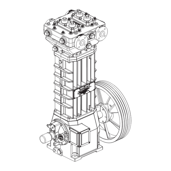
Model WFD551
WFD551 Compressor Shown
Warning: (1) Periodic inspection and maintenance of Corken products is essential. (2) Inspection, maintenance and installation of Corken products must be made only by
experienced, trained and qualified personnel. (3) Maintenance, use and installation of Corken products must comply with Corken instructions, applicable laws and safety
standards (such as NFPA Pamphlet 58 for LP-Gas and ANSI K61.1-1972 for Anhydrous Ammonia). (4) Transfer of toxic, dangerous, flammable or explosive substances
using Corken products is at user's risk and equipment should be operated only by qualified personnel according to applicable laws and safety standards.
Advertisement
Table of Contents

Related Manuals for Corken WFD551


Summary of Contents for Corken WFD551
- Page 1 WFD551 Compressor Shown Warning: (1) Periodic inspection and maintenance of Corken products is essential. (2) Inspection, maintenance and installation of Corken products must be made only by experienced, trained and qualified personnel. (3) Maintenance, use and installation of Corken products must comply with Corken instructions, applicable laws and safety standards (such as NFPA Pamphlet 58 for LP-Gas and ANSI K61.1-1972 for Anhydrous Ammonia).
- Page 2 Corken One Year Limited Warranty Corken, Inc. warrants that its products will be free from defects in material and workmanship for a period of 12 months following date of purchase from Corken. Corken products which fail within the warranty period due to defects in material or workmanship will be repaired or replaced at Corken’s option, when returned freight prepaid to: Corken,...
-
Page 3: Table Of Contents
CHAPTER 2—STARTING UP YOUR CORKEN COMPRESSOR ........ -
Page 4: Compressor Features
With a large selection of enough for it to do compression work, they do not provide design options available, Corken offers the most versatile enough sealing to isolate the compression chamber from line of small gas compressors in the world. -
Page 5: Chapter 1-Installing Your Corken Compressor
Thus, Improper piping installation will result in undesirable Corken cannot guarantee a particular noise level from our transmission of compressor vibration to the piping. compressors. However, noise levels from a properly installed Corken compressor should not exceed 85dBa at three feet. -
Page 6: Driver Installation/Flywheels
Constant Weight - Non-Detergent - R&O Inhibited York, N.Y., 10018. Install, use and maintain this equipment Oil product Ambient Temp. according to Corken instructions and all applicable federal, Exxon® state, and local laws and previously mentioned codes. Other 65° - 100° F laws may apply in different industries and applications. -
Page 7: Purging, Padding, Venting And Draining Of Distance Pieces
The higher pressure should be on the open side of the “V”, which is The key to leakage control and oil-free operation of Corken also the side with the spring. compressors is the distance piece. The distance piece is... -
Page 8: Shutdown/Alarm Devices
Piston rod Piston rod Figure 1.6: Model WFD551 distance piece details. codes and regulations should be checked for specific relief is strongly recommended for all applications. Both valve requirements. Also, relief valves may be required at the High Discharge Temperature switch (HDT) and other points in the compressor’s system piping. - Page 9 Water outlet Pressure equalization connection connection Pressure guage connection Water outlet connection Pressure guage connections Connected to Gas inlet intercooler outlet (first stage inlet) (second stage inlet) Water jackets Gas chambers Water inlet Water inlet Water inlet Connected to Gas outlet intercooler inlet (second stage outlet) (first stage outlet)
-
Page 10: Compressor Cooling
The cylinder has one water jacket while the head has to a portable skid. three water jackets. See Figure 1.9 for details. Chapter 2—Starting Up Your Corken Compressor NOTE: Read this entire chapter, then proceed with when installation is complete. Always check the flywheel the startup checklist. -
Page 11: Crankcase Oil Pressure Adjustment
Adjustment Please verify each item on this list below before starting your compressor! Failure to do so may result Your Corken compressor is equipped with an in a costly (or dangerous) mistake. automatically reversible gear type oil pump. It is... -
Page 12: Chapter 3-Routine Maintenance Chart
2. Observe noise and vibration levels. Correct immediately 7. Verify proper lubrication rate (lubed units only). if excessive. 8. Test each shutdown device and record set points. 3. Verify proper compressor speed. 9. Test or confirm set point on all relief valves. 4. -
Page 13: Chapter 4-Routine Service And Repair Procedures
If routine maintenance is performed as listed in chapter screw by removing each of the four bolts. The 3, repair service on your Corken gas compressor is holddown screw is easily removed with the special generally limited to replacing valves or piston rings. -
Page 14: Reverse Unloader Option
5. To ensure the valve gasket is properly seated, insert To unload a compressor, the reverse unloader holds the the holddown screw and tighten to the value listed compressor valves open approximately ten seconds in Appendix B. or until the compressor and motor reach a normal operating RPM. -
Page 15: Piston Replacement
5. Piston rings and expanders may then be easily 4. Now measure dimension “X”, shown in figure 4.4. If removed and replaced. Corken recommends replacing this measurement does not fall within the tolerances expanders whenever rings are replaced. To determine... -
Page 16: Cylinder Replacement
4.6.1 Cylinder Installation and Alignment Piston must not touch cylinder! To check this clearance, Your Corken compressor is a precision piece of equipment assembly personnel will need to check clearance with with very close tolerances. Treat it as such. Never beat feeler gauges. -
Page 17: Bearing Replacement For Crankcase And Connecting Rod
2. Remove the compressor head, pistons and cylinder. 3. Push down on washer and install retainer ring. 3. Remove the cartridge holddown screw and cage. 4. Install packing installation cone (part number 4005) over the threaded end of the piston rod. 4. - Page 18 the lubrication hole in the bushing matches the oil from the crankshaft and then remove the bearing carrier passage in the connecting rod. and crankshaft from the crankcase. If corrosion or pitting is present, the roller bearings should be replaced. DO NOT MACHINE THE O.D.
-
Page 19: Oil Pump Inspection
Following a few simple procedures will greatly minimize the 3. Check the oil pump shaft bushing in the bearing carrier. risk of the unit becoming corroded and damaged. Corken If the bushing is corroded, pitted or worn, the oil pump recommends the following precautions to protect the shaft bushing should be replaced. -
Page 20: Model Number Identification Code
Appendix A—Model Number Identification Code for WFD551 MODEL NUMBER WFD551 BASE MODEL NUMBER 1" ANSI* BASE X X X X X X X X X X Inlet* 1" ANSI* Outlet* 1" ANSI* Intercooler connection* Ship weight (lbs.) *All ANSI flanges are 300 lb. -
Page 21: Material Specifications
Appendix B—Material Specifications for Model WFD551 Equipment Type & Options Two-stage high pressure design Oil-free design Single distance piece (D-style) has two sets of packing Water cooled cylinder, head and packing 300# ANSI flange connections Material Specifications Part Standard Material... - Page 22 Appendix B—Mechanical Specifications for Model WFD551 Mechanical Specifications Bolt Torque Values Specification All Models 551 Connecting rod bolt 40 ft•lb Bore of cylinder, inches (mm) Bearing carrier 40 ft•lb first stage 4.0 (101.6) Bearing cover 40 ft•lb second stage 2.5 (63.5) Crankcase inspection plate 9 ft•lb...
-
Page 23: Specifications
Appendix B—Mechanical Specifications for Model WFD551 Clearances and Dimensions Description 1st Stage 2nd Stage Clearance: Conrod bearing to crankshaft journal 0.0013/0.0033 Clearance: Wrist pin to wrist pin bushing* (max) 0.001 Cylinder bore diameter (max) 2.515 4.015 Cylinder finish (RMS) Piston ring radial thickness (min) 0.090... -
Page 24: Outline Dimensions
Appendix C—Outline Dimensions Model WFD551 Bare Compressor with Flywheel... - Page 25 Appendix C—Outline Dimensions Model WFD551 with 103 Mounting...
-
Page 26: Troubleshooting
Appendix D—Troubleshooting In most cases, problems with your Corken gas compressor compressors along with a list of possible causes. If you can be solved quite simply. This chart lists some of the are having a problem which is not listed, or if you cannot more frequent problems that occur with reciprocating find the source of the problem, consult the factory. -
Page 27: Assembly Details
Appendix E—Head Assembly Details for Model WFD551 Water outlet connection Water outlet connection (connects tubing to the bottom of the cylinder) Head Assembly Bill of Materials Part No. Description Qty. Part No. Description Qty. 2136 Center head bolt Pipe plug (1/4" NPT) remove for... - Page 28 Appendix E—1st Stage Valve Assembly Details for Model WFD551 1st Stage Suction 1st Stage Suction 1st Stage Discharge (Specification 6P—Reverse Unloader) (Specification 4P—Standard) (All Specifications) Spring down Spring up Head and Valve Assembly Bill of Materials Part No. Description Qty.
- Page 29 Appendix E—2nd Stage Valve Assembly Details for Model WFD551 2nd Stage Suction 2nd Stage Suction 2nd Stage Discharge (Specification 6P—Reverse Unloader) (Specification 4P—Standard) (All Specifications) Spring down Spring up Head and Valve Assembly Bill of Materials Part No. Description Qty.
- Page 30 Appendix E—Valve Assembly Details for Model WFD551 Valve Assemblies—First Stage Valve Assemblies—Second Stage Suction Valve Discharge Valve Suction Valve Discharge Valve Valve Assembly Bill of Materials Valve Assembly Bill of Materials Part No. Description Qty. Part No. Description Qty. 3856-3X2...
- Page 31 Appendix E—Piston Assembly Details for Model WFD551 First Stage Second Stage Piston rod Torque socket head screws and locknut to the value listed in Appendix B. WARNING Piston Assembly Bill of Materials 1st Stage 2nd Stage Piston Assembly No. 1987-X...
- Page 32 Appendix E—Connecting Rod Assembly Details for Model WFD551 Connecting Rod and Crosshead Assembly Bill of Materials Part No. Description 3544-X5 Crosshead assembly Crosshead assembly—coated 3544-X6 piston rod 3590 Retainer ring 1726 Bolt 3785-X1 Connecting rod assembly 3785 Connecting rod 1727...
- Page 33 Appendix E—Packing Assembly Details for Model WFD551 Packing Assembly Bill of Materials Part No. Description V-ring Packing 5000-175 Retainer ring Direction 1728 Washer 1731 Spring Upper Packing 1724 Male packing ring Speci cation “A” 1725 V-ring packing Upper 1723 Female packing ring...
- Page 34 Appendix E—Crosshead Guide Assembly Details for Model WFD551 Backside View of Cylinder 2 (water inlet) Water inlet Crosshead Guide Bill of Materials Part No. Description 5269 Cylinder 2825 Pipe plug (1-1/2" NPT) 2-243_ O-ring 2-247_ O-ring 1749 Cartridge holddown screw...
- Page 35 Appendix E—Flywheel Assembly Details for Model WFD551 Back Side Flywheel Assembly Bill of Materials Assembly Number Assembly Name Flywheel assembly 1762-X (flywheel, hub, and three bolts) Flywheel: 19.5" 1762 O.D., 4 groove Hub with three H E-2.125 bolts and lockwashers...
- Page 36 Appendix E—Crankcase Assembly Details 63 (Pipe plug on under side of crankcase is not shown) Inside of Bearing Carrier Oil Passage Hole Line up hole in gasket with oil passage hole. WARNING Pump Cover Oil/Filter Adapter Pumpside of adapter shown for (Includes all parts shown except #52 and #53) proper orientation of cover and location of pump cover pin.
- Page 37 Appendix E—Crankcase Assembly Details Crankcase Assembly Bill of Materials Part No. Description Part No. Description 2-112A c 1737 Bearing cone O-ring 2805-X a 3638 Spacer Pump shaft bushing 3635 Drive sprocket 1629 Pipe plug (1/16 NPT fl. seal) 1284 Crankshaft orifice 1736 Bearing cup 2135...
- Page 40 Solutions beyond products... CORKEN, INC. • A Unit of IDEX Corporation 9201 North I-35 Service Road, Oklahoma City, OK. 73131 Phone (405) 946-5576 • Fax (405) 948-7343 Visit our website at www.corken.com or e-mail us at cocsalesdept@idexcorp.com @CorkenInc Printed in the U.S.A.
Need help?
Do you have a question about the WFD551 and is the answer not in the manual?
Questions and answers