Table of Contents
Advertisement
Available languages
Available languages
Quick Links
ANS Z21.11.2-2019
ALLEN + ROTH and logo design are
trademarks or registered trademarks
of LF, LLC. All rights reserved.
WARNING: If the information in this manual is not followed exactly, a fire or
explosion may result causing property damage, personal injury, or loss of life.
Do not store or use gasoline or other flammable vapors and liquids in the vicinity of this or any
•
other appliance.
WHAT TO DO IF YOU SMELL GAS:
•
• Do not try to light any appliance.
• Do not touch any electrical switch; do not use any phone in your building.
• Immediately call your gas supplier from a neighbor's phone. Follow the gas supplier's instructions.
• If you cannot reach your gas supplier, call the fire department.
Installation and service must be performed by a qualified installer, service agency, or the gas supplier.
•
This is an unvented gas-fired heater. It uses air (oxygen) from the room in which it is installed.
Provisions for adequate combustion and ventilation air must be provided. Refer to the AIR FOR
COMBUSTION AND VENTILATION section on page 8 of this manual.
This appliance may be installed in an aftermarket, permanently located, manufactured (mobile) home,
where not prohibited by local codes. This appliance is only for use with propane or natural gas. This
appliance is equipped with a simple means to switch between propane and natural gas. Field
conversion by any other means including the use of a kit is not permitted.
Questions, problems, missing parts? Before returning to your retailer, call our customer service
department at 888-534-1578, 9 a.m. - 5 p.m., EST, Monday - Friday.
You could also contact us at support@hhdyn.com or visit www.lowes.com.
HH2202DFS, 220317
welcoming
CAUTION —FOR YOUR SAFETY
!
INSTALLER: Leave this manual with the appliance.
CONSUMER: Retain this manual for future reference.
•
sophisticated
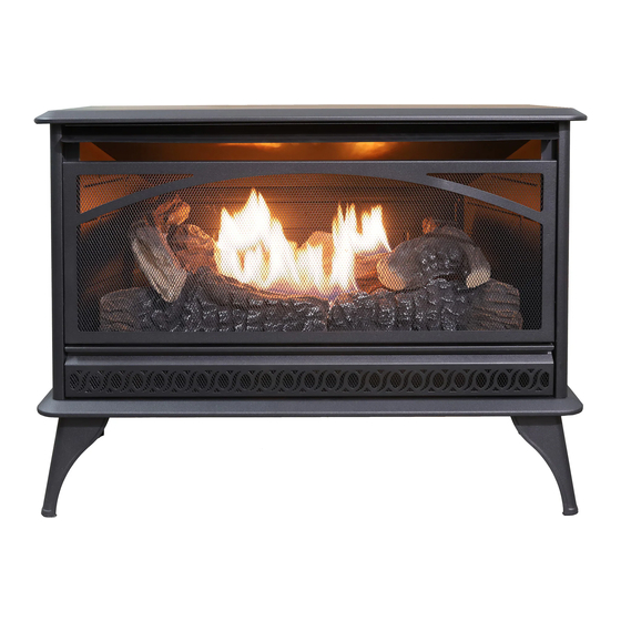
VENT-FREE DUAL FUEL
GAS STOVE HEATER
•
inspiring
ITEM #4976297
MODEL #ARSTDF26I
Español p. 33
Advertisement
Table of Contents

Subscribe to Our Youtube Channel
Summary of Contents for Allen + Roth ARSTDF26I
- Page 1 ITEM #4976297 VENT-FREE DUAL FUEL GAS STOVE HEATER ANS Z21.11.2-2019 MODEL #ARSTDF26I ALLEN + ROTH and logo design are trademarks or registered trademarks CAUTION —FOR YOUR SAFETY Español p. 33 of LF, LLC. All rights reserved. WARNING: If the information in this manual is not followed exactly, a fire or explosion may result causing property damage, personal injury, or loss of life.
-
Page 2: Table Of Contents
Only a qualified installer, service agent, or local gas supplier may install and service this product. ARSTDF26I *For Purpose of Input Adjustment... -
Page 3: Safety Information
Safety Information WARNING WARNING FIRE, EXPOLSION, AND ASPHYXIATION HAZARD Improper adjustment, alteration, service, maintenance, or installation of this heater or its controls can cause death or serious injury. Read the following instructions and precautions in User's Information Manual provided with this heater. - Page 4 Safety Information (cont.) WARNING: • Any safety screen or guard removed for servicing an appliance must be replaced prior to operating the heater. • Any change to this heater or its controls can be dangerous. • Do not use a blower insert, heat exchanger insert or other accessory not approved for use with this heater. •...
- Page 5 Safety Information (cont.) QUALIFIED INSTALLING AGENCY: Only a qualified agency should install and replace gas piping, gas utilization equipment, or accessories, and/or repair and service such equipment. “Qualified agency” means any entity that either in person or through a representative is engaged in and is responsible for: •...
-
Page 6: Product Identification
Product Identification Model: ARSTDF26I DUAL FUEL CAPABILITY The heater is equipped to operate on either propane or natural gas. The heater is shipped from the factory ready for connecting to propane. The heater can easily be changed to natural gas by having your qualified installer follow the instructions on page 17 and the markings on the heater. -
Page 7: General Preparation
General Preparation LOCAL CODES Install and use the heater with care. Follow all local codes. The installation must conform with local codes or, In the absence of local codes, with the latest edition of The National Fuel Gas Code, ANS Z223.1/NFPA 54*. *Available from: American National Standard Institute, Inc. -
Page 8: Preparing For Installation
Preparing for Installation WATER VAPOR IS A BY-PRODUCT OF UNVENTED ROOM HEATERS Gas combustion creates water vapor as a by-product. Unvented room heaters create about one (1) ounce (30 ml) of water for every 1,000 BTUs (0.3 kW) of gas input per hour. An unvented room heater is recommended as a supplemental heat source for a single room rather than as a primary heat source for an entire house. - Page 9 Preparing for Installation (cont.) DETERMINING FRESH-AIR FLOW FOR THE HEATER LOCATION Determining if You Have a Confined or Unconfined Space: Use the below information to determine if you have a confined or unconfined space. Your space includes the room in which you will install the heater plus any other rooms that are directly connected and have doorless passageways or ventilation grills between the rooms.
- Page 10 Preparing for Installation (cont.) If the area in where the heater operates does not meet the required volume for WARNING indoor combustion air, you must provide combustion and ventilation air by one of the methods described in the NATIONAL FUEL GAS CODE, ANS Z223.1/NFPA 54, the INTERNATIONAL FUEL GAS CODE, or applicable local codes.
-
Page 11: Installation
Installation NOTICE: This heater is intended to be used as a supplemental heating source. Use this heater along with your primary heating system. This heater must not be used as a primary heat source. If you have a central heating system, you may run that system’s circulating blower while using this heater. This helps to circulate the heat around your house. - Page 12 Installation (cont.) HEATER CLEARANCES For convenience and efficiency, install the heater with these points in mind: • Provide easy access for operation, inspection and service. • Install the heater in the coldest part of the room. If this heater is installed directly on carpeting, tile, or other combustible material, other than wood flooring, the heater must be installed on a metal or wood panel that extends the heater’s full width and depth.
- Page 13 Installation (cont.) POSITIONING THE HEATER This heater sets on the floor by using the Support Legs included. For convenience and efficiency, install the heater as follows: • In a location with easy access for operation, inspection, and service. • In the coldest part of the room. •...
- Page 14 Installation (cont.) INSTALLING THE HHFAN100 BLOWER (OPTIONAL) Fig. 5—Grounded Three-Prong Receptacle Electrical grounding instructions: This appliance is WARNING equipped with a three-prong (grounding) plug for your protection against shock hazard and should be plugged directly into a properly grounded three-prong receptacle (See Fig. 5). Disconnect heater from the gas supply before installing the fan Fig.
- Page 15 Installation (cont.) INSTALLING THE BLOWER (OPTIONAL) - continued 4. Route wire harness through channel in the back corner of the stove. There are two observation ports on the back of the stove to assist in routing the wire harness. Before securing blower assembly to the stove, put a wire clip on wire harness and snap into the inside of the stove back panel.
- Page 16 Installation (cont.) INSTALLING THE BLOWER (OPTIONAL) - continued Fig. 11—Installing Switch and securing wires 6. Snap Switch into opening in control panel, making sure to position the Auto function on top. Wire clips and a cable tie are provided to help keep the wire harness away from the hot firebox and burner (see Fig.
- Page 17 Installation (cont.) GAS SELECTION INSTRUCTIONS WARNING: This appliance can be used with propane or natural gas. It is shipped from the factory adjusted for use with propane. CAUTION: The knob to the gas selection means shall not be accessed or adjusted while the appliance is in operation.
- Page 18 Installation (cont.) CONNECTING TO A GAS SUPPLY WARNING A qualified service technician must connect heater to gas supply. Follow all local codes. Never connect the heater to private/non-utility gas wells (commonly known as WARNING wellhead gas). CAUTION Never connect the heater directly to the gas supply. This heater requires an external regulator (not supplied).
- Page 19 Installation (cont.) CAUTION Use pipe joint sealant that is resistant to gas (propane or NG). We recommend that you install a sediment trap in a supply line, which traps moisture and contaminants. The sediment trap should be located within reach for cleaning and where it is not likely to freeze. Install it in the piping system between the fuel supply and heater.
- Page 20 Installation (cont.) CHECKING GAS CONNECTIONS After installing or servicing the heater, test all gas piping and connections for leaks. WARNING Immediately correct all leaks. Never use an open flame to check for a leak. Apply a mixture of liquid soap and water WARNING to all joints—bubbles may indicate a leak.
-
Page 21: Log Placement
Log Placement Failure to position the parts in accordance with these diagrams or failure to use only parts WARNING specifically approved with this heater may result in property damage or personal injury. Number of Logs: 5 Check to ensure that no yellow flame comes in CAUTION contact with any log, both after installation and periodically afterwards. -
Page 22: Operation
Operation FOR YOUR SAFETY READ BEFORE LIGHTING If you do not follow these instructions exactly, a fire or explosion may result WARNING causing property damage, personal injury or loss of life. A. This appliance has a pilot that must be lighted by the piezo ignitor. When lighting the pilot, follow these instructions exactly. - Page 23 Operation (cont.) LIGHTING INSTRUCTIONS 1. STOP! Read all the above safety information before proceeding. Fig. 22 Control Knob 2. Open the Lower Access Panel located below the heater screen. Turn the control knob clockwise to the “OFF” position (see Fig. 22). 4.
- Page 24 Operation (cont.) INSPECTING BURNERS Check the pilot flame pattern and burner flame patterns often. PILOT FLAME PATTERN Figure 24 shows a correct pilot flame pattern. Figure 25 shows an incorrect pilot flame pattern. The incorrect pilot flame is not touching the thermocouple. This will cause the thermocouple to cool. When the thermocouple cools, the heater will shut down.
-
Page 25: Care And Maintenance
Care and Maintenance BURNER FLAME PATTERN Figure 26 shows a correct burner flame pattern. Figure 27 shows an incorrect burner flame pattern. The incorrect burner flame pattern shows sporadic, irregular flame tipping. The flame should not be dark or have an orange/reddish tinge. NOTE: When using the heater the first time, the flame will be orange for approximately one hour. - Page 26 Care and Maintenance (cont.) 1. Shut off the heater, including the pilot. Allow the heater to cool for at least 30 minutes. 2. Inspect the burner, pilot, and primary air inlet holes on the orifice holder for dirt and debris (see Fig. 28). 3.
-
Page 27: Troubleshooting Guide
Troubleshooting Guide WARNING If you smell gas, do the following: • Shut off gas suppl . • Do not try to light any appliance. • Do not touch any electrical switch; do not use any phone in your building. • Immediately call your gas supplier from a neighbor’s phone . Follow the gas supplier’s instructions. •... - Page 28 Troubleshooting Guide (cont.) Problem Possible Cause Solution 1. Control knob is not fully pressed in. 1. Press in control knob fully. 2. Control knob is not pressed in 2. After ODS/pilot lights, keep control knob pressed long enough. in 30 seconds. ODS/pilot lights but 3.
- Page 29 Troubleshooting Guide (cont.) Problem Possible Cause Solution White powder 1. When heated, the vapors from 1. Turn heater off when using furniture polish, wax, carpet cleaner or similar products. residue is forming furniture polish, wax, carpet within burner box or cleaners, etc.
-
Page 30: Parts List
Parts List For replacement parts, contact 1-888-534-1578. Vent-Free Gas Stove User’s Manual... -
Page 31: Limited Warranty
WARRANTY KEEP THIS WARRANTY Always specify model and serial numbers when communicating with customer service. We reserve the right to amend these specifications at any time without notice. The only warranty applicable is our standard written warranty. We make no other warranty, expressed or implied. LIMITED WARRANTY VENT-FREE GAS SPACE HEATERS This product is warranted to be free from defects in materials and components and limited labor for (3) THREE years... - Page 32 Printed in China ALLEN + ROTH and logo design are trademarks or registered trademark of LF, LLC. All rights reserved.
- Page 33 DOS COMBUSTIBLES TIPO ESTUFA SIN VENTILACIÓN ANS Z21.11.2-2019 ALLEN+ROTH diseño MODELO #ARSTDF26I logotipo son marcas comerciales o marcas registradas de LF, LLC. PRECAUCIÓN: PARA SU SEGURIDAD Todos los derechos reservados. ADVERTENCIA: Si la información de este manual no se sigue estrictamente, puede producirse un incendio o una explosión que ocasione daños a la propiedad, lesiones personales o la muerte.
- Page 34 El incumplimiento de estas instrucciones puede provocar lesiones personales u ocasionar un peligro de incendio y anulará la garantía. Solo un instalador calificad , agente de servicio o proveedor de gas local puede instalar y dar servicio a este producto. ARSTDF26I N.º de modelo: Máx. Clasificación de e trada 25,408...
- Page 35 Información de seguridad ADVERTENCIA: PELIGRO DE INCENDIO, EXPLOSIÓN Y ASFIXIA El ajuste, la alteración, el servicio, el mantenimiento o la instalación inadecuados de este calentador o sus controles puede causar lesiones graves o la muerte. Lea las siguientes instrucciones y precauciones en el Manual del usuario que se proporciona con este calentador ADVERTENCIA: ENVENENAMIENTO POR MONÓXIDO DE CARBONO:...
- Page 36 Información de seguridad (cont.) ADVERTENCIA: • Antes de hacer funcionar el calentador, debe volver a colocar en su lugar cualquier pantalla o protector de seguridad que haya quitado para realizar el mantenimiento del aparato. • Cualquier cambio en este calentador o sus controles puede ser peligroso. •...
- Page 37 Información de seguridad (cont.) AGENCIA DE INSTALACIÓN CALIFICADA: Solo una agencia calificada debe instalar y eemplazar tuberías de gas, equipos de utilización de gas o accesorios, y/o reparar y dar mantenimiento a dichos equipos. “Agencia calificad ” significa cualquier e tidad que, ya sea en persona o a través de un representante, participa y es responsable de: •...
- Page 38 Identifi ación de producto Modelo: ARSTDF26I Gabinete de la estufa Pantalla Patas de Perilla de soporte Quemador Botón de control encendido CAPACIDAD PARA DOS COMBUSTIBLES El calentador está equipado para funcionar con propano o gas natural. El calentador se envía desde la fábrica listo para conectarlo a propano.
- Page 39 Preparación general CÓDIGOS LOCALES Instale y utilice el calentador con cuidado. Siga todos los códigos locales. La instalación debe cumplir con los códigos locales o, en ausencia de códigos locales, con la última edición de The National Fuel Gas Code, ANS Z223.1/NFPA 54*.
- Page 40 Preparación para la instalación EL VAPOR DE AGUA ES UN SUBPRODUCTO DE LOS CALENTADORES DE HABITACIÓN SIN VENTILACIÓN La combustión de gas crea vapor de agua como un subproducto. Los calentadores de habitación sin ventilación crean aproximadamente una (1) onza (30 ml) de agua por cada 1,000 BTU (0.3 kW) de entrada de gas por hora. Se recomienda un calentador de habitación sin ventilación como fuente de calor suplementaria para una habitación individual, en lugar de como fuente de calor principal para toda una casa.
- Page 41 Preparación para la instalación (cont.) DETERMINACIÓN DEL FLUJO DE AIRE FRESCO PARA LA UBICACIÓN DEL CALENTADOR Cómo determinar si tiene un espacio confinado o no onfinado Utilice la siguiente información para determinar si tiene un espacio confinado o no onfinad . Su espacio incluye la habitación en la que instalará...
- Page 42 Preparación para la instalación (cont.) ADVERTENCIA: Si el área en la que funciona el calentador no cumple con el volumen requerido para el aire de combustión interior, debe proporcionar aire de combustión y ventilación a través de uno de los métodos descritos en el código NATIONAL FUEL GAS CODE, ANS Z223.1/NFPA 54, el código INTERNATIONAL FUEL GASCODE, o los códigos locales correspondientes.
- Page 43 Instalación AVISO: Este calentador está diseñado para usarse como fuente de calor suplementaria. Use este calentador junto con su sistema de calefacción principal. Este calentador no debe utilizarse como fuente de calor principal. Si tiene un sistema de calefacción central, puede hacer funcionar el soplador de circulación de ese sistema mientras usa este calentador.
- Page 44 Instalación (cont.) ESPACIOS LIBRES PARA EL CALENTADOR Para mayor comodidad y eficiencia, instale el cale tador teniendo en cuenta estos puntos: • Proporcione fácil acceso para el funcionamiento, inspección y servicio. • Instale el calentador en la parte más fría de la habitación. Si este calentador se instala directamente sobre alfombras, baldosas u otro material combustible, que no sea un piso de madera, el calentador debe instalarse en un panel de metal o madera que abarque el ancho y la profundidad completos del calentador.
- Page 45 Instalación (cont.) COLOCACIÓN DEL CALENTADOR Este calentador se coloca en el piso utilizando las patas de soporte incluidas. Para mayor comodidad y eficiencia, instale el cale tador de la siguiente manera: • En un lugar con fácil acceso para el funcionamiento, inspección y servicio. •...
- Page 46 Instalación (cont.) Fig. 5—Receptáculo INSTALACIÓN DEL SOPLADOR HHFAN100 (OPCIONAL) de tres clavijas con conexión a tierra ADVERTENCIA: Instrucciones de conexión a tierra eléctrica: Este aparato está equipado con un enchufe de tres clavijas (conexión a tierra) para su protección contra el peligro de descarga eléctrica y debe enchufarse directamente en un receptáculo de tres clavijas correctamente conectado a tierra (consulte la Fig.
- Page 47 Instalación (cont.) INSTALACIÓN DEL SOPLADOR (OPCIONAL) - continuación 4. Pase el arnés de cableado a través del canal en la esquina posterior de la estufa. Hay dos mirillas en la parte posterior de la estufa para ayudar a tender el arnés de cableado. Antes de acoplar el conjunto del soplador a la estufa, coloque una abrazadera para cable en el arnés de cableado y engánchela en el interior del panel posterior de la estufa.
- Page 48 Instalación (cont.) INSTALACIÓN DEL SOPLADOR (OPCIONAL) - continuación Fig. 11—Instalación del interruptor y fijación de los cables 6. Encaje el interruptor en la abertura del panel de control, asegurándose de ubicar la función Auto en la parte superior. Se proporcionan abrazaderas para cables y sujetacables para ayudar a mantener el arnés de cableado alejado de la cámara de combustión caliente y Si el cable es un poco largo, acomode el cable...
- Page 49 Instalación (cont.) INSTRUCCIONES PARA LA SELECCIÓN DE GAS ADVERTENCIA: Este aparato se puede usar con propano o gas natural. Se envía desde la fábrica configu ado para su uso con propano. PRECAUCIÓN: No debe accederse ni ajustarse la perilla de los medios de selección de gas mientras el aparato esté...
- Page 50 Instalación (cont.) CONEXIÓN A UN SUMINISTRO DE GAS Un técnico de servicio calificado debe conectar el calentador al suministro de ADVERTENCIA: gas. Siga todos los códigos locales. Nunca conecte el calentador a pozos de gas privados/no públicos ADVERTENCIA: (comúnmente conocidos como gas en boca de pozo). PRECAUCIÓN: Nunca conecte el calentador directamente al suministro de gas.
- Page 51 Instalación (cont.) PRECAUCIÓN: Utilice sellador para juntas de tubería que sea resistente al gas (propano o GN). Recomendamos instalar una trampa de sedimentos en una línea de suministro, que atrape la humedad y los contaminantes. La trampa de sedimentos debe ubicarse donde sea accesible para la limpieza y donde no es probable que se congele.
- Page 52 Instalación (cont.) VERIFICACIÓN DE LAS CONEXIONES DE GAS ADVERTENCIA: Después de instalar o darle mantenimiento al calentador, pruebe todas las tuberías y conexiones de gas para detectar fugas. Corrija inmediatamente todas las fugas. ADVERTENCIA: Nunca use una llama abierta para verificar si hay fugas. Aplique una mezcla de jabón líquido y agua a todas las juntas;...
- Page 53 Colocación de leños ADVERTENCIA: Si no se colocan las piezas de acuerdo con estos diagramas o no se utilizan únicamente piezas específicame te aprobadas para este calentador, se pueden producir daños a la propiedad o lesiones personales. ADVERTENCIA: Verifique que ninguna llama amarilla Cantidad de leños: 5 entre en contacto con ningún leño, tanto después de la instalación como periódicamente después de ella.
- Page 54 Operación PARA SU SEGURIDAD, LEA ANTES DE ENCENDER Si no sigue estas instrucciones estrictamente, puede producirse un incendio o ADVERTENCIA: una explosión que cause daños a la propiedad, lesiones personales o la muerte. A. Este aparato tiene un piloto que debe encenderse con el encendedor piezoeléctrico. Cuando encienda el piloto, siga estas instruccionesestrictamente.
- Page 55 Funcionamiento (cont.) INSTRUCCIONES DE ENCENDIDO 1. ¡DETÉNGASE! Lea toda la información de seguridad anterior antes de Fig. 22 Perilla de control continuar. 2. Abra el panel de acceso inferior ubicado debajo de la pantalla del calentador. 3. Gire la perilla de control en sentido horario hasta la posición “OFF”...
- Page 56 Funcionamiento (cont.) INSPECCIÓN DE QUEMADORES Revise el patrón de llama del piloto y los patrones de llama del quemador con frecuencia. PATRÓN DE LLAMA DEL PILOTO La Figura 24 muestra un patrón de la llama del piloto correcto. La Figura 25 muestra un patrón de la llama del piloto incorrecto.
- Page 57 Cuidado y mantenimiento PATRÓN DE LLAMA DEL QUEMADOR La Figura 26 muestra un patrón de la llama del quemador correcto. La Figura 27 muestra un patrón de la llama del quemador incorrecto. El patrón de llama incorrecto del quemador muestra una inclinación esporádica e irregular de la llama. La llama no debe ser oscura ni tener un matiz anaranjado/rojizo.
- Page 58 Cuidado y mantenimiento (cont.) 1. Apague el calentador, incluido el piloto. Deje que el calentador se enfríe durante al menos 30 minutos. 2. Inspeccione el quemador, el piloto y los orificios de e trada de aire principales en el soporte del orifici , en busca de suciedad y residuos (consulte la Fig.
- Page 59 Guía de resolución de problemas ADVERTENCIA: Si huele a gas, haga lo siguiente: • Cierre el suministro de gas. • No intente encender ningún aparato. • No toque ningún interruptor eléctrico; no use ningún teléfono en su edifici . • Llame inmediatamente a su proveedor de gas desde el teléfono de un vecino. Siga las instrucciones del proveedor de gas.
- Page 60 Guía de resolución de problemas (cont.) Problema Posible causa Solución El piloto de seguridad 1. La perilla de control no está 1. Presione completamente la perilla de control. con sensor de completamente presionada. 2. Después de que se encienda el piloto de seguridad con sensor disminución de 2.
- Page 61 Guía de resolución de problemas (cont.) Problema Posible causa Solución Se forman residuos de polvo blanco dentro de 1. Cuando se calientan, los vapores de la cera 1. Apague el calentador cuando use cera para muebles, cera, la caja del quemador o para muebles, cera, limpiadores de alfombras, limpiador de alfombras o productos similares.
- Page 62 Lista de piezas Para obtener piezas de repuesto, comuníquese con llamando 1-888-534-1578. Manual del usuario para estufa a gas sin ventilación...
- Page 63 GARANTÍA CONSERVE ESTA GARANTÍA Siempre especifique el modelo y los núme os de serie cuando se comunique con el servicio de atención al cliente. Nos reservamos el derecho de enmendar estas especificaciones en cualquier mome to sin previo aviso. La única garantía aplicable es nuestra garantía estándar por escrito.
- Page 64 Impreso en China ALLEN + ROTH y el diseño del logotipo son marcas comerciales o marcas registradas de LF, LLC. Todos los derechos reservados.
Need help?
Do you have a question about the ARSTDF26I and is the answer not in the manual?
Questions and answers