Table of Contents
Advertisement
Quick Links
Installation and Operation Manual
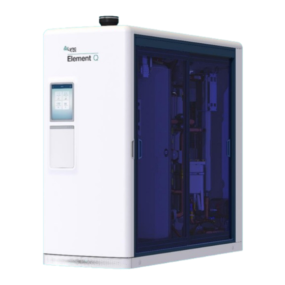
Element Q
This Manual Applies to models:
•
Element Q 100
•
Element Q 80
•
Element Q 60
This manual applies to serial numbers:
21LN0001 and above
Patents Pending
Disclaimer
The information contained in this manual is subject to change without notice
from Lync by Watts, LLC. Lync makes no warranty of any kind with respect to
this material, including, but not limited to, implied warranties of merchantability
and fitness for a particular application. Lync is not liable for errors appearing in
this manual, not for incidental or consequential damages occurring in
connection with the furnishing, performance, or use of these materials.
L-OMM-003_0A • 10/12/2021
®
Lync • 425 W. Everman Pkway, St. 101 • Fort Worth, TX 76134
Technical Support • (800) 433-5654 (ext. 3) • Mon-Fri, 8 am - 5 pm CST
Engineered Solutions
USA: T: (817) 335-9531
© 2021 Lync by Watts, LLC
Advertisement
Table of Contents
Troubleshooting

Related Manuals for Watts Lync Element Q


Summary of Contents for Watts Lync Element Q
- Page 1 Disclaimer The information contained in this manual is subject to change without notice from Lync by Watts, LLC. Lync makes no warranty of any kind with respect to this material, including, but not limited to, implied warranties of merchantability and fitness for a particular application. Lync is not liable for errors appearing in this manual, not for incidental or consequential damages occurring in connection with the furnishing, performance, or use of these materials.
-
Page 2: Table Of Contents
Element Section 1: Safety Precautions Table of Contents SAFETY PRECAUTIONS ........................7 Warnings & Cautions ..........................7 Emergency Shutdown ..........................8 Prolonged Shutdown ..........................8 For Massachusetts Installations ......................... 9 GENERAL INFORMATION ......................11 Safety Considerations ..........................11 Electrical Requirements ........................... 12 Handling and Locating the Element ...................... - Page 3 Element Section 1: Safety Precautions Combining Category IV Vents ........................31 7.3.1 Concentric Vent Connections to the Vent Pipe and Remote Air Inlet Duct ..........32 7.3.2 Concentric Vent Kit Assembly, Installation and Support ................32 Connecting to an Existing Vent System ..................... 33 SECTION II –...
- Page 4 Element Section 1: Safety Precautions 10.1 Edge SC Controller Description ......................... 69 10.2 Welcome Screen and Navigation ......................69 10.3 Menu Structure ............................71 10.3.1 Water Heater ............................73 10.3.2 Unit Anti-Scale ............................74 10.3.3 UV Cold Water and UV Recirculation ......................75 10.3.4 Mixing Valve .............................
- Page 5 Element Section 1: Safety Precautions DIGITEMP JR. MIXING VALVE ....................110 12.1 Description ............................110 12.1.1 Repair ..............................110 12.2 Setup and Programming ........................111 12.2.1 To Create a Passcode: ..........................112 12.2.2 To Unlock the System: ..........................113 12.2.3 System Setup Menu ..........................
- Page 6 Element Section 1: Safety Precautions 16.5.3 Blowdown Valve ............................. 141 16.5.4 Diverter Valve ............................142 APPENDIX..............................144 APPENDIX A. STATUS, FAULT MESSAGES ................... 144 APPENDIX B. DIAGRAMS ........................146 APPENDIX C. USER PERMISSIONS TABLE ................... 155 APPENDIX D. CHANGE LOG ....................... 157 (This page intentionally blank) •...
-
Page 7: Safety Precautions
Element Section 1: Safety Precautions SAFETY PRECAUTIONS 1.1 Warnings & Cautions Installers and operating personnel MUST, at all times, observe all safety regulations. The following warnings and cautions are general and must be given the same attention as specific precautions included in these instructions. In addition to all the requirements included in this AERCO Instruction Manual, the installation of units MUST conform with local building codes, or, in the absence of local codes, ANSI Z223.1 (National Fuel Gas Code Publication No. -
Page 8: Emergency Shutdown
Element Section 1: Safety Precautions CAUTION! Many soaps used for gas pipe leak testing are corrosive to metals. The piping must be rinsed thoroughly with clean water after leak checks have been completed. DO NOT use this heater if any part has been under water. Call a qualified service technician to inspect and replace any part that has been under water. -
Page 9: For Massachusetts Installations
Element Section 1: Safety Precautions 1.4 For Massachusetts Installations Water heater Installations within the Commonwealth of Massachusetts must conform to the following requirements: • Heater must be installed by a plumber or a gas fitter who is licensed within the Commonwealth of Massachusetts. - Page 10 Element Section 1: Safety Precautions 2. Product Approved side wall horizontally vented gas fueled equipment installed in a room or structure separate from the dwelling, building or structure used in whole or in part for residential purposes. (c) MANUFACTURER REQUIREMENTS - GAS EQUIPMENT VENTING SYSTEM PROVIDED. When the manufacturer of Product Approved side wall horizontally vented gas equipment provides a venting system design or venting system components with the equipment, the instructions provided by the manufacturer for installation of the equipment and the venting system shall include:...
-
Page 11: General Information
Element Section 2: General Information 2 GENERAL INFORMATION 2.1 Safety Considerations Follow these WARNINGS and CAUTIONS at all times. Failure to follow these instructions can cause property damage, personal injury, exposure to hazardous materials or death. • Initial startup of all Lync units must be performed by factory-trained personnel so as not to void the warranty. -
Page 12: Electrical Requirements
Element Section 2: General Information 2.2 Electrical Requirements See appliance rating decal for electrical service requirements. The appliance must be electrically supplied and grounded in accordance with the requirements of the authority having jurisdiction or, in the absence of such requirements, with the latest edition of the National Electrical Code ANSI/NFPA No. - Page 13 Element Section 2: General Information Mixing valve Mixed Filter 2 Heating Return Filter 1 Cold Figure 2 - Element Summary Schematic You will notice when opening the front door of Element that the controllers for the various subsystems are all located in front. All wiring is connected to these front panels with external communication and power connections at the rear.
- Page 14 Element Section 2: General Information Figure 3 - Front of unit, door assembly removed • Technical Support • (800) 526-0288 • Mon-Fri, 8 am - 5 pm EST L-OMM-0003_A 10/8/2021 Page 14 of 157...
-
Page 15: Installation
Element Section 3: Installation 3 INSTALLATION 3.1 Description The Element is the first all-in-one, fully engineered water wellness solution that provides safe, reliable domestic hot water through a complete, compact system designed and built by a single source, and operated by a supervisory controller. It integrates water heating, temperature control, and water treatment;... - Page 16 Element Section 3: Installation Input Requirements Natural gas pressure >3.5in W.C. flowing (872 Pa), <14in W.C. static (3487 Pa). Convertible to use LP gas (propane) Electrical service 120VAC, 30A Exhaust venting Use a Category IV PVC, CPVC or ETL, UL, ULC or CSA listed stainless steel or Centrotherm InnoFlue SW Polypropylene vent.
-
Page 17: Receiving And Inspecting The Unit
Element Section 3: Installation Internal and external communications are covered by a separate Element Communications Manual for System Integrators. Refer to that for connections to building automation systems (BAS) or building management systems (BMS). The Edge SC Controller contains a highly sensitive capacitive touchscreen. It continuously checks for user interaction at a high frequency. -
Page 18: Moving The Element
Element Section 3: Installation The unit must be moved with the proper equipment (forklift, pallet jack, etc.) to avoid possible injury to personnel or damage to the shipping container or unit. The shipping carton should be inspected for any damage incurred during transit prior to signing the bill of lading. NOTE: Each unit has a Tip-N-Tell indicator on the outside of the shipping container, which indicates if the unit has been turned on its side during shipment. - Page 19 Element Section 3: Installation Moving the Unit with a Crane: Remove the rear, top cover panel to expose the rear eyebolts. Open the front door to fasten the front rigging hooks. Spreader bars are recommended when lifting with a crane, to prevent damage to the unit. Figure 5 –...
-
Page 20: Site Selection And Preparation
Element Section 3: Installation Moving the Unit with Crossbars: Insert crossbars through the entire width of the unit. Hole diameter is 1.5in (3.8cm). The width of Element is 35.5in (90.2cm). Figure 7 – Crossbar Insertion Points 3.4 Site Selection and Preparation No concrete pad is required for installation of the Element. -
Page 21: Service Clearances
Element Section 3: Installation 3.4.1 Service Clearances All Element models are packaged in enclosures that have identical exterior dimensions. The unit must be installed with sufficient clearance for service access. The recommended clearance dimensions are listed below. However, if local building codes require additional clearances, these codes take precedence. -
Page 22: Electrical Service
Element Section 3: Installation 3.5 Electrical Service Figure 9 – Location of power and interlocks Figure 10 – Power and interlocks The Element requires a 120VAC single phase electrical connection going into the rear power and interlock panel. The “neutral” connection from the building power supply should be connected to the upper 30A circuit breaker, and the “hot/line”... -
Page 23: General Piping Guidelines
Element Section 4: General Piping Guidelines 4 GENERAL PIPING GUIDELINES 4.1 Inlet and Outlet Connections W A R N I N G : Hot outlet and cold-water piping materials connected to this product must be suitable for temperatures up to 212ºF at normal operating water pressures. 1. -
Page 24: Building Return Piping
Element Section 4: General Piping Guidelines 4.2 Building Return Piping Figure 11 – Element Example Installation 4.3 Flow Requirements The pressure drop across Element from cold inlet to hot and mixed outlets is negligible due to the internal booster pump. Minimum flow capacity is a C of 5.8 during a building power outage. -
Page 25: Condensate Drain, Trap & Disposal
Element Section 5: Condensate Drain, Trap & Disposal 5 CONDENSATE DRAIN, TRAP & DISPOSAL The Element is designed to operate with normal cold inlet water temperatures of > 100°F and to produce a significant amount of condensate. The condensate drain is under slightly positive flue pressure, so the provided ¾"... -
Page 26: Condensate Neutralization System (Cns)
Element Section 5: Condensate Drain, Trap & Disposal Figure 13 – Condensate Trap Without Condensate Neutralizer 5.2 Condensate Neutralization System (CNS) The Element is shipped with an optional field-installed CNS. Condensate is acidic (3 to 5 pH). In some locations, local codes require it to be neutralized prior to entering a suitable drainage system. -
Page 27: Gas Supply And Piping
Element Section 6: Gas Supply and Piping 6 GAS SUPPLY AND PIPING Verify the type of gas specified on rating plate is supplied to the unit. This unit is designed for operation up to 2000 feet altitude. Appliance Btu/h input derates 4% per 1000 feet elevation above sea level. -
Page 28: Venting
Element Section 7: Venting 7 VENTING All Element models use the positive pressure generated by the burner system blower to push combustion products out of the vent. Since the vent system is under positive pressure and must be capable of containing condensate, it must be constructed of schedule 40 solid PVC or CPVC pipe. - Page 29 Element Section 7: Venting 7. Clean and deburr all solid PVC or CPVC pipe ends, then trial assemble the entire vent system vent before joining with cement. Mark the pipe and fittings to identify their locations, then disassemble. Reassemble the vent system using fresh PVC cement to connect PVC pipe and fresh CPVC cement to connect CPVC pipe.
-
Page 30: Maximum Vent Length (Equivalent Length)
Element Section 7: Venting 7.1 Maximum Vent Length (Equivalent Length) The maximum length of field supplied Category IV vent is shown in Table 5 below: 6” Duct 8” Duct Duct Size Max Equivalent Length Model Q 60 and Q 80 250 feet / 10 300 feet / 10 Max Equivalent Length Model Q 100... -
Page 31: Combining Category Iv Vents
Element Section 7: Venting 8. A horizontal vent terminal must not be installed closer than 3 feet (0.91m) from an inside corner of an L-shaped structure. 9. A vertical vent must exhaust outside building at least 3 feet (0.91m) above the exit and at least 2 feet (0.61 m) above high point of roof within a 10-foot (3.05 m) radius of termination. -
Page 32: Concentric Vent Connections To The Vent Pipe And Remote Air Inlet Duct
Element Section 7: Venting Figure 14 – Concentric Vent Dimensions 7.3.1 Concentric Vent Connections to the Vent Pipe and Remote Air Inlet Duct 1. The Element can obtain combustion air and exhaust products of combustion through 4” exhaust IPEX System Concentric Vent Termination Kit. This option is not currently available for water heater models LC9Q and LC10Q. -
Page 33: Connecting To An Existing Vent System
Element Section 7: Venting d) Use straps, clamps or equivalent that will not score or damage the pipe. Do not constrain or clamp the vent system anywhere between the Element and the vent termination point such that it is unable to expand or contract as it heats and cools during operation. e) The weight of the concentric kits must be supported by clamps/straps and not by the vent system it connects to. -
Page 34: Section Ii - Element Startup Procedure
Element Section 8: Water Heater and AquaSolve Startup: Section II – Element Startup Procedure Startup of Element essentially consists of two parts: first the water heater (Section 8) and second the controls system (Section 9.) In order to prevent potential damage if energizing the unit dry, breakers 3, 5, and 6 are set open (turned off) during shipment. -
Page 35: Water Heater And Aquasolve Startup
Element Section 8: Water Heater and AquaSolve Startup: Figure 16 – Location of local circuit breakers 8 WATER HEATER AND AQUASOLVE STARTUP 8.1 Initial Startup Requirements Installation must be complete before performing initial startup and placing the Element unit into service. -
Page 36: Resources
Element Section 8: Water Heater and AquaSolve Startup: • Two U-tube Manometers or pressure gauges • AC/DC Multi-meter (with 20,000 OHM/Volt rating) • Amp Meter • Normal Hand Tools 8.3 Resources • Product Installation & Maintenance Manuals • Start-up Report with instructions •... -
Page 37: Confirm Water Tanks Are Completely Filled
Element Section 8: Water Heater and AquaSolve Startup: 2. At the rear of the Element, remove the panel screws on the left service panel per Figure 17 a) Check if terminals R1 and R2 are jumped. If they are, nothing more needs to be done. If the terminals are not jumped but have wires connected to them, this indicates that a remote on/off relay is controlling the water heater from the Building Automation System. -
Page 38: Check Tank Flanges And Plumbing Connections For Leaks
Element Section 8: Water Heater and AquaSolve Startup: Use of colder water may cause condensation and cause burner lockout. To remove condensation: after startup is complete and the water has reached proper temperature, turn the booster water heater OFF; remove the condensation drain plug and allow condensation to drain; replace drain plug and turn booster water heater back ON. -
Page 39: Startup Procedure
Element Section 8: Water Heater and AquaSolve Startup: IMPORTANT: If the supply gas pressure is outside of the allowable range, notify the building maintenance personnel or installer to reduce the gas pressure to the water heaters. 7. Open manual shutoff valve at inlet of gas train. Check the train for leaks using a soap solution. -
Page 40: Burner Combustion Adjustment - General
Element Section 8: Water Heater and AquaSolve Startup: 8.6.1 Burner Combustion Adjustment – General W A R N I N G ! If carbon monoxide is in excess of 200 ppm at any point, do not operate unit. Contact your Lync representative for assistance. -
Page 41: Check The Vent Pressure
Element Section 8: Water Heater and AquaSolve Startup: 11. Once the desired Low Fire combustion levels are achieved, return to the touch screen and increase the HTR MOD firing rate to the maximum High Fire rate for the specific product. NOTE: The maximum factory-set High Fire firing rate may not be 100%. -
Page 42: Water Heater Interlocks
Element Section 8: Water Heater and AquaSolve Startup: Figure 18 – Gas Train Illustration NOTE: Optional components may not be shown. 8.6.4 Water Heater Interlocks As a safety measure for interfacing with an Energy Management System, the Lync Q Water Heater includes interlocks that connect to remote devices such as draft dampers, gas pressure gauges, and air proving switches. - Page 43 Element Section 8: Water Heater and AquaSolve Startup: Terminal Description Connections Provides a 5 Amp contact closure to control remote equipment (e.g. mechanical room air louvers, draft inducer or power vent, etc.). Do not directly energize pumps or motors through these terminals. If operation or repositioning of the P1 –...
-
Page 44: Aquasolve Media Fill
Element Section 8: Water Heater and AquaSolve Startup: Figure 19 - Interlocks and Controls Terminal Block 8.7 AquaSolve Media Fill In systems with new copper piping, such as new construction or recently repaired domestic hot water piping, copper and flux may temporarily increase the copper content of the supply water above the recommended operating limits for the AquaSolve scale prevention system. -
Page 45: Controls Startup
Software → Install Update. Follow the steps in Section 10.4.7.1. Certified technicians can download the latest firmware from the Lync Learning Management System (LMS) website at https://training.watts.com , or by contacting your local Lync rep. 9.3 Change Owner PIN on Unit Upon start up, it is highly recommended to change the PIN for the Owner role at this time. - Page 46 Element Section 9: Controls Startup Figure 20 – Go to the Settings Page and click on Manage Users Figure 21 – Click on the Owner User Profile • Technical Support • (800) 526-0288 • Mon-Fri, 8 am - 5 pm EST L-OMM-0003_A 10/8/2021 Page 46 of 157...
-
Page 47: Communication Wiring
Element Section 9: Controls Startup Figure 22 – Change PIN in owner profile Figure 23 – Create new PIN CAUTION Keep your PIN information in a safe place. PIN recovery for an Owner requires assistance from Lync technical support and your Lync rep. 9.4 Communication Wiring Before Element is connected to the network or the cloud or when communication is interrupted, Element can continue to operate as a standalone unit. - Page 48 Element Section 9: Controls Startup communicate via the onboard EdgeSC supervisory controller with a Building Automation System (BAS) or Building Management System (BMS) using either BACnet® or Modbus® protocols. The EdgeSC is designed with integrated communication as one of its main features. In addition to the I/Os, it connects to a BMS and the cloud using two primary methods: •...
-
Page 49: Initial Bas Connectivity
Element Section 9: Controls Startup Figure 24 – Location of network and BAS connections via ethernet or RS485 at the rear of the unit. 9.5 Initial BAS Connectivity Ensuring a secure connection to the data within Element is critical to ensure appropriate service to the domestic hot water system. -
Page 50: Initial Startup And The First User
Element Section 9: Controls Startup 2. Confirm that a network connection is established by scrolling to the network connections section and observing a checkmark and IP address for Ethernet. Figure 26 – Network Settings If an IP address is not present, check the rear of the unit in the low voltage section of the electrical compartment for a proper network connection to ENET 1 per Figure 24. - Page 51 Element Section 9: Controls Startup 4. First-time myLync users must navigate to the web app at http://www.mylyncbywatts.com. Click on Create an Account. This can also be performed through the myLync mobile app, available on the Google Play® store or on the Apple® app store. NOTE: This address is different from the main Lync product page.
- Page 52 Azure so if the user has another account within Azure, they can log in using those credentials. For most first-time users, fill out the information shown in Figure 29. Figure 29 - Create a new account with Watts 6. The user can now log in. Navigate back to http://mylyncbywatts.com...
- Page 53 Element Section 9: Controls Startup Figure 30 – Login page 7. The user is now able to create an organization and the associated hierarchy within their buildings. See Section 9.7 for more information. 8. If the initial user is the installer or the Lync rep, they are now a part of the organization. Follow Section 9.9 to perform an ownership transfer to the first customer user.
- Page 54 Element Section 9: Controls Startup Figure 31 • Technical Support • (800) 526-0288 • Mon-Fri, 8 am - 5 pm EST L-OMM-0003_A 10/8/2021 Page 54 of 157...
- Page 55 – Installation and Operation Manual Element Section 9: Controls Startup Figure 32 – New User Dashboard on Web App 1. Click on Select an org. No organizations are available, so click on Add Organization. Figure 33 – Add a new organization 2.
- Page 56 – Installation and Operation Manual Element Section 9: Controls Startup Figure 34 – New organization entry 3. As the creator of the organization, you are the owner. Ownership can be transferred per 9.9.1 after another user is added to the organization. 4.
- Page 57 – Installation and Operation Manual Element Section 9: Controls Startup Figure 36 – Add a Unit Within the Site 6. The pop-up window will ask for a Unit Code and a Unit Name. Figure 37 – Add Unit Information 7. Type in a Unit Name of your choosing. The Unit Code comes from the Element itself so it can be associated with the site and organization.
-
Page 58: Setting Up The Organization Hierarchy
– Installation and Operation Manual Element Section 9: Controls Startup Figure 38 – Connecting a Unit to the Cloud 8. This creates a unique, temporary cloud commissioning code. This code expires in 25 minutes once generated. Please enter the following code into the myLync App Figure 39 –... - Page 59 – Installation and Operation Manual Element Section 9: Controls Startup Units are organized by Organization, Site, Building, Plant, and Unit. The hierarchy assists with organizing individual units, defining user permissions, organizing reports, and communication between staff members. Figure 40 – Hierarchy of locations Organization The parent organization of the customer Site...
-
Page 60: Managing Users
– Installation and Operation Manual Element Section 9: Controls Startup Creating a new organization is shown in section 9.6 Figure 33. Creating a new site is shown in section Creating a new building is found when navigating to the site page, clicking on Actions, and clicking on Add New Building. -
Page 61: Invite New Users
– Installation and Operation Manual Element Section 9: Controls Startup 9.8.1 Invite New Users Figure 41 – Go to the user page within the myLync app • Technical Support • (800) 526-0288 • Mon-Fri, 8 am - 5 pm EST L-OMM-0003_A 10/8/2021 Page 61 of 157... - Page 62 – Installation and Operation Manual Element Section 9: Controls Startup Figure 42 – Click on "+ Invite" to invite a new user to the organization Figure 43 – Go to the Users page and click on “+ Invite User” • Technical Support •...
-
Page 63: Reassigning Personas
Section 9: Controls Startup Figure 44 – Invite new users 9. The user then will receive an email from no-reply@watts.com with the ability to create a new cloud account. NOTE: It is recommended that users keep the same email address for multiple units, plants, buildings, sites, and organizations (especially important for individuals who manage multiple clients’... -
Page 64: Organization Ownership Transfer
– Installation and Operation Manual Element Section 9: Controls Startup transfer is handing the keys to your car to someone else: you will no longer have access without their permission. There are three methods of ownership transfer: 1. At the unit for a non-cloud-connected unit, the initial Owner can transfer ownership to another user. - Page 65 – Installation and Operation Manual Element Section 9: Controls Startup Figure 45 - Organization transfer from owner screen on mobile app • Technical Support • (800) 526-0288 • Mon-Fri, 8 am - 5 pm EST L-OMM-0003_A 10/8/2021 Page 65 of 157...
- Page 66 – Installation and Operation Manual Element Section 9: Controls Startup Figure 46 - Organization transfer from receiving screen on mobile app When the receiving user logs into their mobile app again (close and reopen the app if necessary), they will see the Ownership Transfer Invitation. They may choose to accept it, decline it, or close the window.
- Page 67 – Installation and Operation Manual Element Section 9: Controls Startup Figure 47 - Organization transfer using web app • Technical Support • (800) 526-0288 • Mon-Fri, 8 am - 5 pm EST L-OMM-0003_A 10/8/2021 Page 67 of 157...
-
Page 68: Troubleshooting Ownership Transfer
– Installation and Operation Manual Element Section 9: Controls Startup 9.9.2 Troubleshooting Ownership Transfer • Cannot perform ownership transfer No other users besides the Owner within the organization. Invite and add a user. • Target user rejected transfer. Communicate and try again. •... -
Page 69: Section Iii - Sub-System Details
Element Section 10: Edge SC Controller Operation Section III – Sub-System Details 10 EDGE SC CONTROLLER OPERATION The information in this Chapter provides a guide to the operation of the Element using the Edge SC Controller. Initial startup of this unit should only be performed by factory trained personnel. Operation prior to initial startup by factory trained personnel will void the equipment warranty. - Page 70 Element Section 10: Edge SC Controller Operation The Edge Controller SC allows users to view each component of the Element along with the status, alerts, temperature (if applicable), monitoring and event history. The intuitive menu highlights the selected component and displays all connected parts. The user can toggle between the various components to view their status or check alerts.
-
Page 71: Menu Structure
Element Section 10: Edge SC Controller Operation 10.3 Menu Structure The System Status menu provides a dashboard of the Element and the status of each of the ten (10) subsystems within the Element: • • Water Heater Blowdown Valve • •... - Page 72 Element Section 10: Edge SC Controller Operation Figure 51 – Menu Structure The five (5) menu shortcuts on the bottom provide specific visibility into the Element: • System Status • Infection Control • Sanitation • Maintenance Log • Settings The following sections show examples of the display along with corresponding submenus for each selection.
-
Page 73: Water Heater
Element Section 10: Edge SC Controller Operation 10.3.1 Water Heater The Water Heater screen shows the component’s current status. Options also include viewing the Process Output Temperature, editing the current Set Point and editing the alert thresholds. Edit Set Point: Edit Alert Thresholds: Figure 52 –... -
Page 74: Unit Anti-Scale
Element Section 10: Edge SC Controller Operation 10.3.2 Unit Anti-Scale The Lync AquaSolve anti-scale subsystem prevents scaling of minerals such as calcium and magnesium salts within the DHW system and downstream fittings. The Anti Scale screen shows the component’s current status. Options include viewing the media life, logging an order or replacement, and editing alert thresholds. -
Page 75: Uv Cold Water And Uv Recirculation
Element Section 10: Edge SC Controller Operation 10.3.3 UV Cold Water and UV Recirculation The ultraviolet (UV) subsystems disinfect water that passes through the Element, with one subsystem for the cold inlet for incoming water and a second subsystem for the recirc inlet for ongoing disinfection in the DHW loop. -
Page 76: Mixing Valve
Element Section 10: Edge SC Controller Operation 10.3.4 Mixing Valve The mixing valve provides tempered water for distribution using the integral Lync DigiTemp Jr subsystem that complies with ASSE 1017. The Mixing Valve screen shows the component’s current status and tempered supply temperature. -
Page 77: Filters: Cold Water And Recirculation
Element Section 10: Edge SC Controller Operation 10.3.5 Filters: Cold Water and Recirculation The 5µm integrated filters promote proper function of the UV systems by minimizing sediment to allow UV light to reach any microorganisms. They also remove sediment that would otherwise enter the DHW system to create surfaces for biofilm to grow, or to feed the biofilm nutrients. -
Page 78: Booster Pump
Element Section 10: Edge SC Controller Operation Figure 56 – Cold Water Filter 10.3.6 Booster Pump The booster pump compensates for internal pressure drops between the cold-water inlet and the outlets. This ensures that there is virtually no pressure drop across the system. The Booster Pump screen shows the component’s current status and PSI pressure. -
Page 79: Diverter Valve
Element Section 10: Edge SC Controller Operation Edit Alert Thresholds Edit Set Point Figure 57 - Booster Pump 10.3.7 Diverter Valve The Diverter Valve screen shows the component’s current status and if the valve is open or closed. Options include editing the adjusting the valve and coordinating a system flush. Adjust Valve System Flush •... -
Page 80: Blowdown Valve
Element Section 10: Edge SC Controller Operation Figure 58- Diverter Valve 10.3.8 Blowdown Valve The Blowdown Valve screen shows the component’s current status and whether the valve is open or closed. Options include starting the Blowdown Cycle and editing the schedule. Disclaimer •... -
Page 81: Sanitation Pump
Element Section 10: Edge SC Controller Operation Configure Schedule Start Blowdown Cycle Figure 59 - Blowdown Valve 10.3.9 Sanitation Pump The Sanitation Pump screen shows the current status and provides options for starting or scheduling sanitation. The Element can perform three (3) types of sanitation: •... - Page 82 Element Section 10: Edge SC Controller Operation Figure 60 - Sanitation Loop Conditioning Set to enable schedule. Set the conditioning cycle duration and interval between cycles and select Confirm to begin. 10.3.9.2 Water Heater Sanitation NOTE: Domestic hot water should be stored above 140°F (60°C) to prevent pathogen proliferation.
- Page 83 Element Section 10: Edge SC Controller Operation It is generally agreed that in a laboratory setting, a temperature of 122°F (30°C) results in an equilibrium point where certain species of Legionella are proliferating and dying at the same rate. Legionella populations begin to reduce at higher temperatures and per the following texts, Legionella die rapidly at temperatures above 158°F (70 °C): ASHRAE.
- Page 84 Element Section 10: Edge SC Controller Operation Figure 61 - Sanitation Loop CAUTION Discharging water at elevated temperatures may cause scalding. Discharging water at elevated temperatures into the DWV system may cause drain line damage. Follow local codes and regulations. A corresponding discharge of cold water may be needed in order to temper the water.
-
Page 85: Monitoring
Element Section 10: Edge SC Controller Operation The Element’s mixed output compensates for this rise in temperature, so the temperature will be controlled to the mixed output setpoint and control limits once reaching steady state. Figure 62 - Sanitation Loop A confirmation screen will display to review the settings provided. -
Page 86: Event History
Element Section 10: Edge SC Controller Operation 10.3.11 Event History Each component allows information to be stored and reviewed in the Event History tab of each menu. The Event History displays open and closed requests and allows users to add comments as needed: Figure 63 - Event History •... -
Page 87: Infection Control
Element Section 10: Edge SC Controller Operation 10.3.12 Infection Control Infection Control displays all events related to the Element. This list shows the event, component and activity beginning with the most recent activity: Figure 64 - Infection Control 10.3.13 Comments Users have the option to add comments within the Event History. -
Page 88: Settings
Element Section 10: Edge SC Controller Operation The example below displays previous comments along with the option to reopen (closed) events or add a new comment: Figure 65 - Comments 10.4 Settings The Settings menu allows users to create and manage user accounts, edit network connection, change unit details, update software and create system backups. -
Page 89: Network Connections
Element Section 10: Edge SC Controller Operation To Create a New User select Manage Users > New User. 1. Fill in the required information and select Continue: 2. The system then prompts the user to create a 4-digit pin number. 10.4.2 Network Connections Network connection settings can be viewed in the screen below. -
Page 90: Cloud Connectivity
W A R N I N G Watts is not responsible for alert failures or loss of remote control connectivity due to external connectivity or power issues. -
Page 91: Time
Element Section 10: Edge SC Controller Operation Figure 70 - Unit Details 10.4.5 Time Select the boxes as shown below to change date, time and time zone. Figure 71 - Time and Date 10.4.6 Units Units displayed can be changed in the drop-down menus below. Temperature can be displayed in either Fahrenheit or Celsius;... -
Page 92: Software Update
Element Section 10: Edge SC Controller Operation 10.4.7 Software Update 10.4.7.1 Installing Updates To update software on the Element click Install Update and follow the prompts. Perform a cloud update if the unit is cloud-commissioned, or use a file loaded onto a USB memory stick. The current system can be backed up onto a USB memory stick or restored from a previous backup. -
Page 93: Communication Specification
Element Section 10: Edge SC Controller Operation 10.5.1 Communication Specification Communication Protocol Modbus over RS485 Physical Layer RS485 Two-Wire plus Signal Ground Baud Rate 2400, 9600, 19200, 57.6k, 115k) (default 19200 bps) Recommended Cable 18 AWG Shielded Twisted-Pair (STP) Transmission Mode RTU or ACSII (default RTU) Maximum Cable Length Without terminating resistors... - Page 94 Element Section 10: Edge SC Controller Operation TABLE 5-1: Modbus points list name address type length topic bas_modbus_id 0x0001 holding system/bas_modbus_id bas_modbus_baud 0x0002 holding system/bas_modbus_baud bas_modbus_data_bits 0x0004 holding system/bas_modbus_data_bits bas_modbus_stop_bits 0x0005 holding system/bas_modbus_stop_bits bas_modbus_parity 0x0006 holding system/bas_modbus_parity bas_modbus_commit_settings 0x0007 holding bas_modbus_last_connect 0x0008 input...
- Page 95 Element Section 10: Edge SC Controller Operation TABLE 5-1: Modbus points list name address type length topic cold_uv_error_code 0x0259 input cold_inlet/uv_disinfect/status_info cold_uv_percent_remaining 0x025A input cold_inlet/uv_disinfect/percent_remaining cold_uv_lamp_op_time 0x025B input cold_inlet/uv_disinfect/lamp_op_time cold_uv_lamp_life_rem 0x025C input cold_inlet/uv_disinfect/lamp_life_rem cold_uv_cumulative_op_time 0x025D input cold_inlet/uv_disinfect/cumulative_op_time cold_uv_order_threshold 0x025E holding cold_inlet/uv_disinfect/order_threshold cold_uv_replace_threshold 0x025F...
-
Page 96: Lync Q Water Heater Operation
Element Section 11: Lync Q Water Heater Operation 11 LYNC Q WATER HEATER OPERATION 11.1 Temperature and Pressure Relief Valve(s) A Temperature and Pressure Relief Valve(s) sized in accordance with ASME Boiler and Pressure Vessel Code, Section IV HLW is installed in the tank. W A R N I N G ! Secure relief valve discharge pipe to a suitable floor drain so hot water does not splash during discharge. -
Page 97: Operating Temperature Control
Element Section 11: Lync Q Water Heater Operation W A R N I N G ! Turn off all electrical service to the unit before accessing the limit or other controls inside the control cabinet or burner vestibule. Close and fasten the control cabinet and burner vestibule cover before restoring electrical service. -
Page 98: Electronic Operating System (Eos)
Element SECTION 10: The Electronic Operating System (EOS) 11.5 Electronic Operating System (EOS) The Electronic Operating System (EOS) consists of three components: • The Platform Ignition Module (PIM) • A plug-in ID card, • The Control Display. The PIM is connected to the control display using an RJ485 patch cable. This able provides all communication between the PIM and display as well as power to the display. -
Page 99: Touch Screen User Interface
Element SECTION 10: The Electronic Operating System (EOS) 11.5.1 Touch Screen User Interface The EOS touchscreen provides one-touch access to view and adjust various Menu setpoints. The touchscreen displays Status Fields, Items, Water Heater Output and Number Fields. It also contains buttons for navigation &... -
Page 100: View Menu (Home Screen - Default Display)
Element SECTION 10: The Electronic Operating System (EOS) 11.5.4 View Menu (Home Screen - Default Display) Menu Icon CTRL TEMP: operating temperature sensed at the top of the tank. Home Button: Returns user to the ‘Home’ screen Press and hold for 3 seconds to access programming menus. -
Page 101: Control System Menus
Element SECTION 10: The Electronic Operating System (EOS) 11.5.5 Control System Menus The control display has multiple access levels. System critical settings will not be available for adjustment. Settings that can be adjusted will display UP and DOWN arrows on the right side of the display. -
Page 102: Changing The Operating Setpoint (User Level Access)
Element SECTION 10: The Electronic Operating System (EOS) 5. Exit the menu by pressing the HOME button. 6. Use the NEXT ITEM or ITEM BACK buttons to navigate to the SOURCE menu. 7. Enter the SOURCE menu. 8. Use the NEXT ITEM or ITEM BACK buttons to navigate to the VENT TYPE menu. 9. -
Page 103: Scheduled Setback (User Level Access)
Element SECTION 10: The Electronic Operating System (EOS) Once the parameters for the time screen have been entered, move to the date and year screen and enter settings in the same manner. 3. To display the real time clock in the VIEW menu, select daylight saving time or choose between a 12 and 24 hour clock, use the NEXT ITEM button to move to the correct screen and then the arrow button to select. -
Page 104: Using The Manual Override Menu (Advanced Level Access)
Element SECTION 10: The Electronic Operating System (EOS) Figure 79 - Scheduled Setback 11.5.10 Using the Manual Override Menu (ADVanced Level Access) The OVERRIDE MENU controls the integral tank circulator and optional SANI pump; it is useful during initial commissioning as well as anytime burner adjustment is necessary. To access the Manual Override menu and enter the Advanced Level access: 1. -
Page 105: Potentiometer (Operating Setpoint For Standalone Operation)
Element SECTION 10: The Electronic Operating System (EOS) NOTE: If the HTR MOD control is activated while the burner is firing, the burner will shut down and recycle. Figure 80 - Manual Override Menu W A R N I N G ! When adjustments are complete and before putting the Element into service, return the MAN OVR function to “AUTO”. -
Page 106: Basic Operational Reference Information
Element SECTION 10: The Electronic Operating System (EOS) an ADVanced access level. Depending on the access level selected, different parameters will become visible and adjustable. Selecting the appropriate access level will make menu navigation easier and minimize the possibility that parameters will be unintentionally changed. 2. -
Page 107: Potentiometer (Adjusting The Setpoint)
Element Operation and Maintenance 11.5.14 Potentiometer (Adjusting the Setpoint) The Platform Ignition Module (PIM) will continue to operate the Element at a 120 degree internal factory setpoint should the touch screen control fail, or communication between the two devices is interrupted. This internal setpoint can be adjusted using the potentiometer to maintain a different operating temperature under these circumstances if desired. - Page 108 Element Operation and Maintenance The Electronic Low Water Cut-Off control is a self-contained electronic device which senses the presence of water at the top of the storage tank. When the presence of water is confirmed, the contacts close on the ELWCO and is sensed by PIM control. The High Temperature Limit is combined in a common probe body with the upper tank sensor.
- Page 109 Element Operation and Maintenance b. The High Limit sensor is confirmed to read below the High Limit set-point. c. The temperature of water in the tank is compared to the temperature control setpoint to determine when to begin firing in heating mode. d.
-
Page 110: Digitemp Jr. Mixing Valve
Element Operation and Maintenance 12 DIGITEMP JR. MIXING VALVE 12.1 Description DigiTemp Jr is a digital mixing valve that provides user-directed control and monitoring water distribution. It includes an electronic Control Module featuring a color touch screen digital display to select desired outlet water temperature, an electronically actuated valve that mixes hot and cold water, a quick response temperature sensor and check valves. -
Page 111: Setup And Programming
Element Operation and Maintenance W A R N I N G ! The procedure below carries exposes personnel to the following hazards: • Hot water and scalding • Burns and hot surfaces • Electrical shock and electrocution Failure to follow all installation requirements risks possible death, personal injury, property damage, and failure of DigiTemp Jr to perform as intended. -
Page 112: To Create A Passcode
Element Operation and Maintenance In the event of a power cycle of Element, there is a potential risk of some of the configurations specific to Element being reset, however this is typically due to a non-volatile memory (NVM) error. Contact your Lync service representative if that error is given. When powered up, the display will show a 100 second countdown timer and read: NOTE: The control will begin mixing operations automatically after 100 seconds. -
Page 113: To Unlock The System
Element Operation and Maintenance 12.2.2 To Unlock the System: To unlock the system, on the Unlock screen, enter your new passcode and then press Enter. NOTE: To clear your entry and start again, press CLEAR. To go back to the Programming menu, press BACK. -
Page 114: Selecting And Setting The Outlet Water Temperature Setpoint
Element Operation and Maintenance You can setup the operation of the system by pressing the System button. To setup operation of the system, continue with the system setup. NOTE: Mixed Setback Offset is only available if a schedule is selected. 12.2.4 Selecting and Setting the Outlet Water Temperature Setpoint: W A R N I N G ! BEFORE setting mixed outlet water temperature or electing default temperature, point-of-use... -
Page 115: Time Function
Element Operation and Maintenance To turn the Mixed Setback Offset feature off, press Mixed Setback Offset on the System Setup menu and press Off and Accept. To change the high temperature alert differential, press High Temp. Alert Diff. in the System Setup menu. - Page 116 Element Operation and Maintenance Once in the Date and Time menu, toggle the radio button to ON and then press Accept. To set date and time, press Set Date and Time from the Time Options menu. To set date and time, select month, date, year, hour, minute and AM/PM icons one at a time and change with UP or DOWN arrows, then press Accept.
- Page 117 Element Operation and Maintenance To select daylight savings time, press Daylight Savings from the Time Options menu. Once in the Daylight Savings menu, toggle the On radio button and press Accept. To view the control type information for your controls, press Firmware from the Toolbox menu and then press Back.
- Page 118 Element Operation and Maintenance To select load temperature units of measure, press Temperature Units in the Toolbox menu. Toggle the radio button to °F for Fahrenheit or °C for Celsius, then press Accept. To adjust the screen brightness, press Screen Brightness from the Toolbox menu.
- Page 119 Element Operation and Maintenance To reset all, press Reset on the Toolbox menu. Toggle the radio button to Yes or toggle to No to retain the current settings. • Technical Support • (800) 526-0288 • Mon-Fri, 8 am - 5 pm EST L-OMM-0003_A 10/8/2021 Page 119 of 157...
-
Page 120: Aquasolve Anti-Scale Operation And Maintenance
Element Operation and Maintenance 13 AQUASOLVE ANTI-SCALE OPERATION AND MAINTENANCE The Lync AquaSolve Anti-Scale System prevents scale formation on internal plumbing surfaces by transforming the normal dissolved hardness minerals into undissolved crystal microparticles. These crystals stay suspended in the water and have a greatly reduced ability to react and attach to surfaces, minimizing scale buildup in pipes, water heaters and on fixtures and glass. -
Page 121: Equipment Specifications
Element Operation and Maintenance The AquaSolve Anti-Scale system performs best in single pass potable water applications with no additional chemical additives. Depending on hardness, soft scale spotting may occur. Soft scale spots in most cases can be easily wiped down with a damp cloth and will not form hard scale deposits. - Page 122 AquaSolve Anti-Scale media. For appli-cations with copper concentration greater than 1.3 ppm, please consult Watts Water Quality Technical Service. To further minimize any problem with excess copper, avoid applying excessive flux on the inner surfaces of the pipe and use a low-corrosivity water soluble flux listed under the ASTM B813 standard.
- Page 123 Element Operation and Maintenance Mechanical Specifications Model LM8414TM-COM LM8416TM-COM Dry Weight 124 lbs / 56 kg 145 lbs / 66 kg Service Weight 458 lbs / 208 kg 550 lbs / 250 kg 2” FNPT 2” FNPT Inlet/Outlet Connection Replacement Media M8414-COM-RM Replace media every 3 years M8416-COM-RM...
-
Page 124: Lync Uv
This equipment should be installed and operated with minimum distance 20cm between the radiator & your body. The Watts UV™ line of ultraviolet disinfection systems provide protection against microbiological contamination in water for residential and commercial applications. Disinfection of water with Lync UV™ is a simple, rapid physical process. When contaminated water is exposed to the Lync UV's™... -
Page 125: Filter Maintenance
Element Operation and Maintenance 15 FILTER MAINTENANCE 15.1 Cold Filter The Element uses a Flow-Max® filter cartridge, model no: FM-5-975. Flow-Max cartridges are washable and reusable, five micron and reduce filtration costs. For best results, direct spray into pleats to dislodge sediment. -
Page 126: Maintenance
Element Operation and Maintenance 16 MAINTENANCE Regular service and routine maintenance must be performed by a qualified service agency or maintenance provider to ensure safe, reliable and efficient operation. To ensure proper maintenance, the following instructions should be posted near the appliance and maintained in legible condition. -
Page 127: Fuse
Element Operation and Maintenance MESSAGE DESCRIPTION LED Flashes MODBUS CODE The PIM control board is not sensing the correct amp draw from the HSI (Hot Surface Igniter). This is most likely LOW HSI caused by a faulty or disconnected igniter. The 24VAC supply to the PIM control is below threshold for LOW 24VAC reliable control operation. -
Page 128: Self-Check/Control Failure
Element Operation and Maintenance 16.1.4 Self-Check/Control Failure The PIM confirms the integrity of the gas valve relay contacts to insure safety. It also monitors the processor memory and software execution for proper program flow. If the control detects an error in its software or hardware, all outputs are turned off and the LED displays a steady ON condition. -
Page 129: Maintenance Schedule
Element Operation and Maintenance PIM Errors LWCO Remote Proof Air Pressure Low Gas Pressure Boiler Outlet/Tank Top Sensor Boiler Inlet/Tank Bottom Sensor Vent Sensor Hi-Limit Sensor Ignition Failure Flame Loss Vent Hi-Limit Boiler/Tank Hi-Limit False Flame OEM Card Internal Failure Hi-Delta Not used Low Voltage... -
Page 130: Cold And Recirc Sediment Filter Maintenance
Element Operation and Maintenance 9. Check the electronic-ignition system for quick ignition and proper flame signal. 10. Check gas safety shut-off valves for proper operation and tightness. 11. Follow startup procedure in this Installation, Operation & Maintenance manual. 16.1.10.2 Semi-Annually (Every 6 Months) 1. -
Page 131: Changing Cold Filter
Element Operation and Maintenance 2. Drain bottom of filter from the hose connection. Air will vent from top of filter housing. 3. Remove all wingnuts and screws from the filter housing cover. 4. Open and remove filter from the housing. Clean or replace with new filter cartridge. 5. -
Page 132: Aquasolve Maintenance
Element Operation and Maintenance Figure 87 - Rear Panel with Locations of Panel Screws Highlighted 3. Open the hose connection to drain the filter, UV, and AquaSolve (Figure 88). 4. Remove the clamp on the filter housing (Figure 89) and remove lid. 5. -
Page 133: Replacing The Media
Element Operation and Maintenance 16.3.1 Replacing the Media 1. Remove the rear panels from Element unit. Each handle panel has 4 wingnuts along the edges that need to be removed. The bottom panel has 4 screws in the corners. Figure 90 – Removing Rear Panel 2. - Page 134 Element Operation and Maintenance 4. Connect drain pipe to AquaSolve ball valve. 5. Vent the AquaSolve tank at the top, center inlet. 6. Open ball valve to drain tank and capture media into a rice bag or sieve for disposal. Open cold-water inlet for 1 minute to flush potential media into suspension to drain.
-
Page 135: Lync Uv Systems Maintenance
Element Operation and Maintenance 16.4 Lync UV Systems Maintenance The Edge SC will inform users when a bulb should be ordered and when it requires replacement (every 9,000 hours). When a bulb or quartz tube needs to be replaced: 1. Isolate the Element from the DHW system and depressurize. De-energize Element. 2. - Page 136 Element Operation and Maintenance Location of Valves to Drain Water from Cold UV reactor Top view location of Lync UV reactor assemblies • Technical Support • (800) 526-0288 • Mon-Fri, 8 am - 5 pm EST L-OMM-0003_A 10/8/2021 Page 136 of 157...
- Page 137 Element Operation and Maintenance 4. Remove the two rear top hatches to expose the tops of both UV assemblies. Place an absorbent cloth around the port to catch any water discharge. 5. Disconnect the lamp lead wire from the glow cap electrical port (Figure 1). 6.
-
Page 138: Component Maintenance And Troubleshooting
Element Operation and Maintenance 16.5 Component Maintenance and Troubleshooting 16.5.1 Sanitation Pump Lync Part Number: 69378 Failure to operate When pump is first started, the shaft may rotate slowly until water has fully penetrated the bearings. If the pump does not run, the shaft can be rotated manually. To accomplish this, switch off the power supply, and close the isolation valves on each side of the pump. -
Page 139: Booster Pump
Element Operation and Maintenance 16.5.2 Booster Pump Lync Part Number: 24695 • Technical Support • (800) 526-0288 • Mon-Fri, 8 am - 5 pm EST L-OMM-0003_A 10/8/2021 Page 139 of 157... - Page 140 Element Operation and Maintenance • Technical Support • (800) 526-0288 • Mon-Fri, 8 am - 5 pm EST L-OMM-0003_A 10/8/2021 Page 140 of 157...
-
Page 141: Blowdown Valve
Element Operation and Maintenance 16.5.3 Blowdown Valve Lync Part Number: 92158 1. After disconnecting the supply voltage and discharging the pressure, inspect the valve. 2. Clean and inspect all the internal parts and replace them if necessary. 3. Remount all the parts making up the solenoid valve with care, paying great attention to the correct position of each part and protecting the sealing surfaces. -
Page 142: Diverter Valve
Element Operation and Maintenance 16.5.4 Diverter Valve Lync Part Number: 92159 W A R N I N G Do not press the clutch while actuator is powered Location of Clutch PC Board • Technical Support • (800) 526-0288 • Mon-Fri, 8 am - 5 pm EST L-OMM-0003_A 10/8/2021 Page 142 of 157... - Page 143 Element Operation and Maintenance 16.5.4.1 Stroke Adjustment 1. Apply power and WAIT FOR LED TO TURN OFF (around 10 seconds). 2. Press the reset button to start auto-stroke process. The LED should illuminate. a. First option: The actuator will then travel in both directions to find its limit and position itself according to the demand.
-
Page 144: Appendix
Element Operation and Maintenance APPENDIX Appendix A. Status, Fault Messages The Element provides alerts to users via email, SMS, and push notifications through the myLync app. These messages can be configured by the user in myLync to appear through the different means of communication. - Page 145 Element Operation and Maintenance Lync UV System Error Codes: Error # Description The UV system is not sufficiently disinfecting. Check bulb life, clean quartz sleeve, clean UVLVRAT_2 UV sensor window, or check UV sensor connection. DigiTemp Jr Mixing Valve Error Codes: Error # Description Mixing valve NVM memory error.
-
Page 146: Appendix B. Diagrams
Element Operation and Maintenance Appendix B. Diagrams • Technical Support • (800) 526-0288 • Mon-Fri, 8 am - 5 pm EST L-OMM-0003_A 10/8/2021 Page 146 of 157... - Page 147 Element Operation and Maintenance • Technical Support • (800) 526-0288 • Mon-Fri, 8 am - 5 pm EST L-OMM-0003_A 10/8/2021 Page 147 of 157...
- Page 148 Element Operation and Maintenance • Technical Support • (800) 526-0288 • Mon-Fri, 8 am - 5 pm EST L-OMM-0003_A 10/8/2021 Page 148 of 157...
- Page 149 Element Operation and Maintenance • Technical Support • (800) 526-0288 • Mon-Fri, 8 am - 5 pm EST L-OMM-0003_A 10/8/2021 Page 149 of 157...
- Page 150 Element Operation and Maintenance • Technical Support • (800) 526-0288 • Mon-Fri, 8 am - 5 pm EST L-OMM-0003_A 10/8/2021 Page 150 of 157...
- Page 151 Element Operation and Maintenance • Technical Support • (800) 526-0288 • Mon-Fri, 8 am - 5 pm EST L-OMM-0003_A 10/8/2021 Page 151 of 157...
- Page 152 Element Operation and Maintenance • Technical Support • (800) 526-0288 • Mon-Fri, 8 am - 5 pm EST L-OMM-0003_A 10/8/2021 Page 152 of 157...
- Page 153 Element Operation and Maintenance • Technical Support • (800) 526-0288 • Mon-Fri, 8 am - 5 pm EST L-OMM-0003_A 10/8/2021 Page 153 of 157...
- Page 154 Element Operation and Maintenance • Technical Support • (800) 526-0288 • Mon-Fri, 8 am - 5 pm EST L-OMM-0003_A 10/8/2021 Page 154 of 157...
-
Page 155: Appendix C. User Permissions Table
Element Operation and Maintenance Appendix C. User Permissions Table Technical Water Chief Facilities Infection Maint. Service Owner Customer Mgmt User Engr Manager Control Tech. Contractor Support Contractor Unit and Remote Experiences Menu Location Permission Type Component Detail Screen - Change Settings System Status Edit System Settings Screen... - Page 156 Element Operation and Maintenance Transfer Ownership Mobile / Web Device Mgmt Create, Edit, and Delete New Site/Building/Plant Mobile / Web Location Mgmt Manage User Access/Permission Levels Mobile / Web User Mgmt Commission new unit System Status Device Mgmt Decommission a Unit System Status Device Mgmt Create New User...
-
Page 157: Appendix D. Change Log
Element Operation and Maintenance Appendix D. Change Log Change Log Date Description Changed By 10/12/2021 Rev A: Initial Release Linley T • Technical Support • (800) 526-0288 • Mon-Fri, 8 am - 5 pm EST L-OMM-0003_A 10/8/2021 Page 157 of 157...
Need help?
Do you have a question about the Lync Element Q and is the answer not in the manual?
Questions and answers