Table of Contents
Advertisement
Quick Links
Advertisement
Table of Contents

Related Manuals for Microchip Technology Microsemi PolarFire MPF300T


Summary of Contents for Microchip Technology Microsemi PolarFire MPF300T
- Page 1 UG0872 User Guide PolarFire MPF300T FPGA Video Kit June 2019...
-
Page 2: Table Of Contents
PolarFire MPF300T FPGA Video Kit Contents 1 Revision History ..........................1 1.1 Revision 1.0 ............................1 2 Introduction ........................... 2 2.1 Kit Contents ............................2 2.2 Block Diagram ............................. 2 2.3 Board Overview ..........................3 3 Hardware Settings ......................... 6 3.1 Jumper Settings .......................... -
Page 3: Revision History
PolarFire MPF300T FPGA Video Kit Revision History The revision history describes the changes that were implemented in the document. The changes are listed by revision, starting with the most current publication. Revision 1.0 Revision 1.0 was the first publication of this document 50200872 UG0872 User Guide Revision 1.0... -
Page 4: Introduction
PolarFire MPF300T FPGA Video Kit Introduction The Microsemi PolarFire® FPGA Video Kit (POLARFIRE VIDEO KIT), which is RoHS-compliant, enables you to evaluate the PolarFire MPF300T-1FCG1152E FPGA for the following interfaces: MIPI CSI-2 RX interface HDMI2.0 HDMI1.4 DDR4 memory FMC HPC with 8 Transceiver lanes UART Interface to the FTDI device SPI Interface to the SPI Flash device Kit Contents... -
Page 5: Board Overview
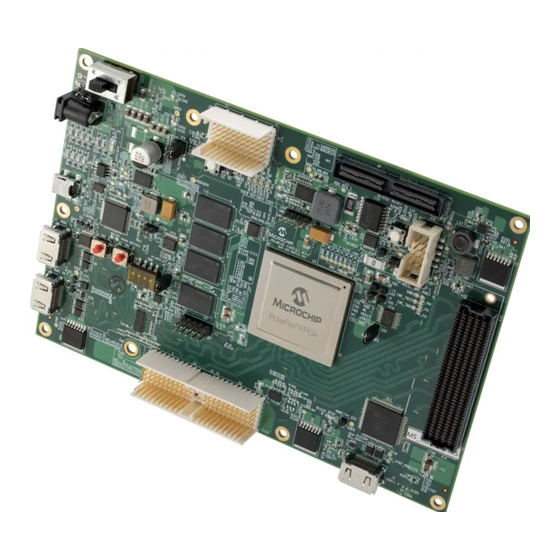
PolarFire MPF300T FPGA Video Kit Figure 1 • Block Diagram Board Overview The following figure shows a labeled image of the video board highlighting its components. Figure 2 • Board Callout 50200872 UG0872 User Guide Revision 1.0... - Page 6 PolarFire MPF300T FPGA Video Kit The following table lists the components of the video board. Table 2 • Board Components Component Label on Description Board Featured Device PolarFire FPGA MPF300T-1FCG1152E FPGA Power Supply 12 V power supply The board is powered by a 12 V power source using an external +12 V/5 A DC jack ON/OFF switch Power ON/OFF switch from +12 V external DC jack Clocks...
- Page 7 PolarFire MPF300T FPGA Video Kit Component Label on Description Board USER Reset switch Push-button system reset for the PolarFire device Users must program this HSIO for PolarFire logic reset function Device reset Device reset 50200872 UG0872 User Guide Revision 1.0...
-
Page 8: Hardware Settings
PolarFire MPF300T FPGA Video Kit Hardware Settings This section provides information about jumper settings, switches, LEDs, and DIP switches on the PolarFire video board. Jumper Settings Connect the jumpers according to the settings specified in the following table. Table 3 • Jumper Settings Jumper Description Pin(s) -
Page 9: Power Sources
PolarFire MPF300T FPGA Video Kit Description DS9-Green VDDA(1V05) Voltage rail DS8-Green VDDAUX4 Voltage rail DS7-Green 1.2V voltage rail DS6-Green VCCIO_HPC_VADJ voltage rail DS12-Green 1.8V HDMI1V4 voltage rail DS13-Green 0.6V VTT voltage rail Power Sources The PolarFire video board uses Microchip power supply devices. For more information about these power supply devices, see: https://www.microchip.com/design-centers/power-management/dc-dc- converters-regulators. - Page 10 PolarFire MPF300T FPGA Video Kit Figure 3 • Power Supply Scheme The following table lists the suggested Microchip power regulators for PolarFire FPGA voltage rails. Table 6 • Power Regulators Voltage Rail Part Number Description Current MIC24055YJL-TR IC REG BUCK ADJ 12A SYNC 28QFN MIC24055YJL-TR IC REG BUCK ADJ 12A SYNC 28QFN MIC24046YFL-TR...
-
Page 11: Board Components And Operations
PolarFire MPF300T FPGA Video Kit Board Components and Operations This section describes the key components of the PolarFire Video board and important board operations. Memory Interface The following figure shows the memory interface scheme. Figure 4 • Memory Interface As shown in the preceding figure, Four 4 Gb DDR4 SDRAM chips are used as flexible volatile memory for user applications. -
Page 12: Hdmi1.4 Interface
PolarFire MPF300T FPGA Video Kit Figure 5 • SPI Flash Interface The SPI flash specifications for the PolarFire device are: Density: 1 Gb Voltage: 2.7 V to 3.6 V (MT25QL01GBBB8ESF-0SIT) Frequency: 90 MHz Quantity = 1 SPI mode support: Modes 0 and 3 HDMI1.4 Interface One HDMI1.4 Transmitter is connected to the PolarFire device to support the HDMI1.4 standard as shown in the following figure. -
Page 13: Mipi-Tx Connector (Dsi Application)
PolarFire MPF300T FPGA Video Kit Figure 7 • MIPI-RX Connection MIPI-TX Connector (DSI Application) The video board supports the MIPI transmitter X4 lanes and clock for DSI application, as shown in the following figure. MIPI TX signals are interfaced to the LCD display. An adaptor board for the LCD display can be connected through the J26 connector on the video board. -
Page 14: Mipi-Tx And Rx Pcb Loopback
PolarFire MPF300T FPGA Video Kit Figure 9 • MIPI-TX Connection (CSI-2 Application)` MIPI-TX and RX PCB Loopback The video board supports the on-board PCB trace loopback of MIPI X4 lanes and clock, as shown in the following figure. Figure 10 • MIPI-TX and RX Loopback Transceivers The PolarFire MPF300T-1FCG1152E... -
Page 15: Xcvr1 And Xcvr3 Blocks
PolarFire MPF300T FPGA Video Kit Figure 11 • XCVR0 Interface 4.8.2 XCVR1 and XCVR3 Blocks XCVR1 and XCVR3 blocks have four lanes each. These lanes are connected to the FMC HPC connector and the signals are routed on the PCB as follows: Lanes 0 to 7 are directly routed to the FMC HPC TX pad >... -
Page 16: Xcvr2 Block
PolarFire MPF300T FPGA Video Kit Figure 12 • XCVR1 and XCVR3 Interface 4.8.3 XCVR2 Block The lanes of the XCVR2 block are connected to HDMI2.0 TX and RX chips via the line drivers chips, as shown in the following figure. This interface can operate up to 6 Gbps. 50200872 UG0872 User Guide Revision 1.0... -
Page 17: Xcvr Reference Clock
PolarFire MPF300T FPGA Video Kit Figure 13 • XCVR2 Interface 4.8.4 XCVR Reference Clock The following figure shows the clock sources for XCVR blocks. Figure 14 • XCVR Reference Clocks XCVR 1A, 3A reference clocks are sources from FMC HPC connector(J14). XCVR 2B reference clock is sourced from the on-board 148.5 MHz XCVR 2A reference clock is sourced from the on-board HMDI2.0 TX Programming... -
Page 18: 50 Mhz Oscillator
PolarFire MPF300T FPGA Video Kit The following figure shows how the JTAG Header interfaces with the PolarFire Device. Figure 15 • JTAG Header Interface Note: By default, the FTDI programming mode is enabled. Remove J28 jumper to enable programming through JTAG header. 4.10 50 MHz Oscillator A 50 MHz clock oscillator with an accuracy of +/-50 ppm is available on the board. -
Page 19: Device Reset
PolarFire MPF300T FPGA Video Kit 4.11 Device Reset As shown in the following figure, DEVRST_N (SW5 push button) is an input-only reset switch that allows assertion of a full reset of the chip at any time. The DEVRST_N signal is an active-low signal. Figure 17 •... -
Page 20: User Leds
PolarFire MPF300T FPGA Video Kit 4.13.1 User LEDs Four active-high LEDs are connected to the PolarFire device. The following table (see page ) lists the on-board label of these switches, the associated PolarFire pin number, name, and Bank. Table 7 • User LEDs Label On Board PolarFire Pin Number PolarFire Pin Name... -
Page 21: Slide Switches (Dpdt)
PolarFire MPF300T FPGA Video Kit Figure 20 • Push-Button Interface 4.13.3 Slide Switches (DPDT) The SW4 slide switch powers the device ON or OFF. 4.13.4 DIP Switches (SPST) The SW6 DIP switch includes 8 connections to the PolarFire device. The following table lists on-board label of these switches, the associated PolarFire pin number, name, and Bank. -
Page 22: Fmc Hpc Connector (J14)
PolarFire MPF300T FPGA Video Kit Figure 21 • DIP Switch Interface 4.13.5 FMC HPC Connector (J14) An HPC (J14) FMC connector is available for future expansion of interfaces. This FMC connector is compliant with the VITA 57.1 specification. The PolarFire Bank4, XCVR1, and XCVR3 signals are routed to the FMC connector (J14) for user application development. - Page 23 PolarFire MPF300T FPGA Video Kit Figure 22 • Silkscreen Top View The following figure shows the bottom view of the placement of board components. 50200872 UG0872 User Guide Revision 1.0...
- Page 24 PolarFire MPF300T FPGA Video Kit Figure 23 • Silkscreen Bottom View 50200872 UG0872 User Guide Revision 1.0...
- Page 25 Within the USA: +1 (800) 713-4113 Outside the USA: +1 (949) 380-6100 Microsemi, a wholly owned subsidiary of Microchip Technology Inc. (Nasdaq: MCHP), offers a comprehensive portfolio of semiconductor and system Sales: +1 (949) 380-6136 solutions for aerospace & defense, communications, data center and industrial markets. Products include high-performance and radiation-hardened Fax: +1 (949) 215-4996 analog mixed-signal integrated circuits, FPGAs, SoCs and ASICs;...
Need help?
Do you have a question about the Microsemi PolarFire MPF300T and is the answer not in the manual?
Questions and answers