
Subscribe to Our Youtube Channel
Related Manuals for Microchip Technology dsPICDEM MCHV-2


Summary of Contents for Microchip Technology dsPICDEM MCHV-2
- Page 1 MCHV-2 Development Board User’s Guide 2012 Microchip Technology Inc. DS52074A...
- Page 2 Select Mode, Total Endurance, TSHARC, UniWinDriver, WiperLock and ZENA are trademarks of Microchip Technology Incorporated in the U.S.A. and other countries. SQTP is a service mark of Microchip Technology Incorporated in the U.S.A. All other trademarks mentioned herein are property of their respective companies.
- Page 3 2012 Microchip Technology Inc. DS52074A-page 3...
- Page 4 MCHV-2 Development Board User’s Guide NOTES: 2012 Microchip Technology Inc. DS52074A-page 4...
-
Page 5: Safety Notice
• The unit is designed to be connected to the AC mains supply via a standard non- locking plug. As the unit has no mains switch, this plug constitutes the means of disconnection from the supply and thus the user must have unobstructed access to this plug during operation. 2012 Microchip Technology Inc. DS52074A-page 5... - Page 6 MCHV-2 Development Board User’s Guide NOTES: 2012 Microchip Technology Inc. DS52074A-page 6...
-
Page 7: Table Of Contents
B.3 Debugging the Application ................67 B.4 Programming an Application ................ 69 B.5 Determining Device Support and Reserved Resources ......70 B.6 Troubleshooting ................... 70 B.7 Settings Dialog and Info Tab ................ 70 2012 Microchip Technology Inc. DS52074A-page 7... - Page 8 MCHV-2 Development Board User’s Guide NOTES: 2012 Microchip Technology Inc. DS52074A-page 8...
- Page 9 MCHV-2 Development Board. ® • Appendix B. “Debugging and Troubleshooting with MPLAB 8” – This appendix provides debug and programming guidance for MPLAB 8 users. 2012 Microchip Technology Inc. DS52074A-page 9...
-
Page 10: Conventions Used In This Guide
Curly braces and pipe Choice of mutually exclusive errorlevel {0|1} character: { | } arguments; an OR selection Ellipses... Replaces repeated text var_name [, var_name...] Represents code supplied by void main (void) user { ... 2012 Microchip Technology Inc. DS52074A-page 10... -
Page 11: Recommended Reading
Plug-In Module (PIM) for Internal Op amp Configuration Information Sheet (DS52062) This document provides device specific information for the dsPIC33EP256MC506 Internal Op amp configuration PIM. To obtain any of these documents, visit the Microchip web site at www.microchip.com. 2012 Microchip Technology Inc. DS52074A-page 11... - Page 12 MPLAB IDE, MPLAB SIM simulator, MPLAB IDE Project Manager and general editing and debugging features. • Programmers – The latest information on Microchip programmers. These include the MPLAB PM3 device programmer and the PICkit™ 3 development programmers. 2012 Microchip Technology Inc. DS52074A-page 12...
-
Page 13: Customer Support
Technical support is available through the web site at: http://support.microchip.com DOCUMENT REVISION HISTORY Revision A (July 2012) This is the initial released version of the document. 2012 Microchip Technology Inc. DS52074A-page 13... - Page 14 MCHV-2 Development Board User’s Guide NOTES: 2012 Microchip Technology Inc. DS52074A-page 14...
-
Page 15: Chapter 1. Introduction
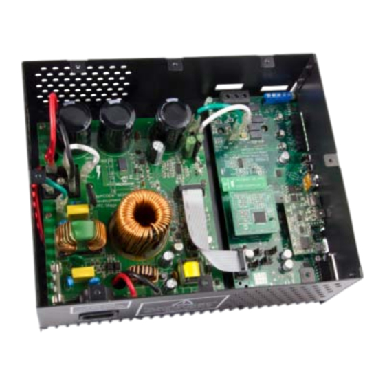
BOARD USER’S GUIDE Chapter 1. Introduction OVERVIEW The Microchip dsPICDEM MCHV-2 Development Board is intended to aid the user in the rapid evaluation and development of a wide variety of motor control applications ® using PIC24 Microcontrollers (MCUs) and dsPIC Digital Signal Controllers (DSCs). - Page 16 MCHV-2 Development Board User’s Guide FIGURE 1-1: dsPICDEM™ MCHV-2 DEVELOPMENT BOARD 2012 Microchip Technology Inc. DS52074A-page 16...
- Page 17 FIGURE 1-2: SYSTEM BLOCK DIAGRAM PFC Stage Board Power Module Board Voltage HALL Hall VAC Voltage Non-isolated Feedback Sensors Sensors Feedback ICSP™ connector Circuitry Circuitry and Motor) VBUS PFC Circuitry VAC Zero Current Crossing Feedback ® dsPIC Circuitry PFC Current PIC24 MCU Power PFC PWM...
- Page 18 MCHV-2 Development Board User’s Guide 1.1.1 Features This section provides some of the key features of the dsPICDEM MCHV-2 Development Board. Motor Control Interfaces: • Three-phase inverter bridge with a power rating of 400V/6.5A (J17) • Hall sensors/Quadrature Encoder Interface (QEI) for sensored motor control algorithms (J9) •...
- Page 19 Built-In Power Supplies: - 15V power supply, maximum power available 11W - 3.3V power supply, maximum power available 2W Additional Protection Circuitry: - 250 VAC/15A fuse - In-rush current limiter - EMI filter 2012 Microchip Technology Inc. DS52074A-page 19...
- Page 20 MCHV-2 Development Board User’s Guide NOTES: 2012 Microchip Technology Inc. DS52074A-page 20...
-
Page 21: Chapter 2. Getting Started
BOARD USER’S GUIDE Chapter 2. Getting Started BOARD COMPONENTS The dsPICDEM MCHV-2 Development Board consists of two stages: • PFC Stage The first stage is integrated by the Power Factor Correction (PFC) circuitry, the full-bridge rectifier, the 15V power supply, and the 3.3V power supply. -
Page 22: User Interface
MCHV-2 Development Board User’s Guide USER INTERFACE The dsPICDEM MCHV-2 has the following components to interact with the user. Figure 2-2 shows a photograph of the front of the system. • Input/Output Control Switches (Figure 2-2): - One isolated push button (S1) - Isolated reset push button (RESET) - Isolated 10 kΩ... -
Page 23: Connecting The System
If possible, all wires should be stripped and tinned with solder before connecting to the dsPICDEM™ MCHV-2 Development Board terminals. 2012 Microchip Technology Inc. DS52074A-page 23... - Page 24 Corresponding tables that describe each connection are provided in the relevant section. FIGURE 2-5: dsPICDEM™ MCHV-2 DEVELOPMENT BOARD CONNECTIONS The power connections are listed in Table 2-1. 2012 Microchip Technology Inc. DS52074A-page 24...
- Page 25 If the motor position is sensed with a Quadrature Encoder, connect the ter- minals phase A, phase B, and Index to the connection nodes HA, HB, and HC (7, 8, and 9 in Figure 2-5), respectively. 2012 Microchip Technology Inc. DS52074A-page 25...
- Page 26 Note: The Microchip serial emulator driver (mchpcdc.inf) should be installed on your PC in order to activate the USB-to-Serial emulator. The emulator can be obtained from the dsPICDEM MCHV-2 Development Board product page: http://www.microchip.com/mchv2 4. Connect the USB cable to the mini-USB female connector labeled “Program/Debug”...
-
Page 27: Power Sequences
Output window. 3. Once the build sequence is complete, MPLAB X will program the target device and begin executing the application code in Debug mode, as shown in Figure 2-7. 2012 Microchip Technology Inc. DS52074A-page 27... - Page 28 ® FIGURE 2-7: MPLAB X WORKSPACE...
- Page 29 Repeatedly click the button to step through the code. 5. Select Debug>Reset click the Reset icon to reset the program again. 6. Select Debug>Finish Debug Session or click the Finish Debug Session icon to exit Debug mode. 2012 Microchip Technology Inc. DS52074A-page 29...
- Page 30 Alternatively, click the Make and Program Device icon to build the application and program the device (this action does not release the device from reset). At this point, the application code will run independently. 2012 Microchip Technology Inc. DS52074A-page 30...
- Page 31 Project Dashboard window of MPLAB X. The project dashboard window also displays other useful information such as Starter Kit on Board V , target device ID, and target device ID revision. 2012 Microchip Technology Inc. DS52074A-page 31...
- Page 32 MCHV-2 Development Board User’s Guide NOTES: 2012 Microchip Technology Inc. DS52074A-page 32...
-
Page 33: Chapter 3. Running The Demonstration
® This chapter describes the demonstration software that is preloaded on the dsPIC device that is included with the dsPICDEM MCHV-2 Development Board. This demon- stration software, which is based on application note AN1162, demonstrates how to use the dsPICDEM™ MCHV-2 Development Board for controlling an AC induction motor (ACIM). - Page 34 MCHV-2 Development Board User’s Guide NOTES: 2012 Microchip Technology Inc. DS52074A-page 34...
-
Page 35: Chapter 4. Hardware
DC bus capacitance. The initial nominal cold resistance is 1 Ohm, which reduces once current flows and the device heats up. • BR1 – A single-phase bridge rectifier to convert the incoming AC into DC suitable for input to the power conditioning stage. 2012 Microchip Technology Inc. DS52074A-page 35... - Page 36 IGBT is turned off. • The power factor corrector design is based on the application note AN1106, for more information on this application note please refer to one of the following Microchip Web sites: www.microchip.com/smps www.microchip.com/motor 2012 Microchip Technology Inc. DS52074A-page 36...
-
Page 37: Power Supplies
DSC, the isolation circuitry, the communication ports, the Starter Kit program- mer, etc. It also generates the 3.3 volts for powering the analog circuits and the analog reference for the Analog-To-Digital Converter (ADC) module. 2012 Microchip Technology Inc. DS52074A-page 37... - Page 38 If possible, all wires should be stripped and tinned with solder before connecting to the dsPICDEM MCHV-2 Development Board terminals. 2012 Microchip Technology Inc.
- Page 39 If possible, all wires should be stripped and tinned with solder before connecting to the dsPICDEM MCHV-2 Development Board terminals. Note: The user should only access the power terminals when the system is fully discharged (see the “Safety Notice”...
-
Page 40: Power Module Stage
PFC current (buffered) Device programming clock line Device programming data line Reference voltage (half of AV voltage) PIM_REC_NEUTR Reconstructed motor neutral line voltage Analog supply Analog supply PIM_POT Potentiometer signal PIM_POT Potentiometer signal 2012 Microchip Technology Inc. DS52074A-page 40... - Page 41 PFC PWM output HA/QEA Hall sensor / QEI input PIM_IB+ IB shunt signal PIM_IA+ IA shunt signal HB/QEB Hall sensor / QEI input PIM_HALLC/INDX/STP_PWM Hall sensor / QEI input PIM_PFC_PWM PFC PWM output 2012 Microchip Technology Inc. DS52074A-page 41...
- Page 42 3.3V digital rail. This auxiliary 3.3V digital rail is applied to the system through R106. The circuit is shown in Appendix A. “Board Layout and Schematics”. Note: It is the responsibility of the user to populate these components if an external power supply is used. 2012 Microchip Technology Inc. DS52074A-page 42...
- Page 43 PIC24 MCU or dsPIC DSC logic levels. R85 limits the current going to the ADC pin (< 6mA). C51, R79 and R84 form the low-pass filter. The phase M2 and M3 has the exact same circuitry as shown in the schematic. 2012 Microchip Technology Inc. DS52074A-page 43...
- Page 44 Plug-In Module. A block diagram describing the matrix board interface is shown in Figure 4-1. FIGURE 4-1: MATRIX BOARD BLOCK DIAGRAM Shunt resistor signals (Direct) Reconstructed motor neutral voltage Feedback signals Matrix Plug-In Module (Hall sensor/Phase voltage/Shunt resistor) Board DC bus voltage Potentiometer 2012 Microchip Technology Inc. DS52074A-page 44...
-
Page 45: Communication Ports
Hardware The dsPICDEM MCHV-2 Development Board uses discrete op amps (U13) to amplify the shunt resistor signals. Alternatively, some of the PIC24 MCUs or dsPIC DSCs include on-board op amps that can be used for this purpose. To accommodate these two basic configurations, the dsPICDEM MCHV-2 Development Board comes with two matrix boards. - Page 46 Connects Hall B/QEB sensor signal to MONITOR_2 Connects DC bus shunt current feedback to MONITOR_3 Connects Phase M3 voltage feedback to MONITOR_3 Connects Hall C/INDEX sensor signal to MONITOR_3 Connects the POT voltage to MONITOR_3 2012 Microchip Technology Inc. DS52074A-page 46...
- Page 47 PGD1/EMUD1 signals is provided by the digital isolators U3, U6, U22 and U7. 4.2.11 Board Connectors Figure 4-2 provides the locations of the connectors. The Power Module Stage Board connectors are listed in Table 4-4. FIGURE 4-2: POWER MODULE BOARD CONNECTORS 2012 Microchip Technology Inc. DS52074A-page 47...
- Page 48 Fault (Overcurrent or Overvoltage condition) Output VAC zero crossing signal Output PFC shunt signal Output PWM signal for the PFC IGBT Input Ground, digital rail Output PWM fault Output Output PFC shunt signal Output 2012 Microchip Technology Inc. DS52074A-page 48...
-
Page 49: Electrical Specifications
PFC IGBT. To provide additional air flow, a conventional AC muffin fan can be used (Comair-rotron part number 028021 or 028023). An alternative bonded fin heat sink with fans attached is also an option (C&H Technology, Inc. part number CH5117F). 2012 Microchip Technology Inc. DS52074A-page 49... - Page 50 MCHV-2 Development Board User’s Guide NOTES: 2012 Microchip Technology Inc. DS52074A-page 50...
-
Page 51: Appendix A. Board Layout And Schematics
MCHV-2 DEVELOPMENT BOARD USER’S GUIDE Appendix A. Board Layout and Schematics FIGURE A-1: PFC STAGE BOARD LAYOUT (TOP) 2012 Microchip Technology Inc. DS52074A-page 51... - Page 52 MCHV-2 Development Board User’s Guide FIGURE A-2: PFC STAGE SCHEMATIC (SHEET 1 OF 3) 2012 Microchip Technology Inc. DS52074A-page 52...
- Page 53 Appendix A FIGURE A-3: PFC STAGE SCHEMATIC (SHEET 2 OF 3) 2012 Microchip Technology Inc. DS52074A-page 53...
- Page 54 MCHV-2 Development Board User’s Guide FIGURE A-4: PFC STAGE SCHEMATIC (SHEET 3 OF 3) 2012 Microchip Technology Inc. DS52074A-page 54...
- Page 55 Appendix A FIGURE A-5: POWER MODULE STAGE BOARD LAYOUT (TOP) 2012 Microchip Technology Inc. DS52074A-page 55...
- Page 56 MCHV-2 Development Board User’s Guide FIGURE A-6: POWER MODULE STAGE BOARD LAYOUT (BOTTOM) 2012 Microchip Technology Inc. DS52074A-page 56...
- Page 57 Appendix A FIGURE A-7: POWER MODULE STAGE SCHEMATIC (SHEET 1 OF 6) 2012 Microchip Technology Inc. DS52074A-page 57...
- Page 58 MCHV-2 Development Board User’s Guide FIGURE A-8: POWER MODULE STAGE SCHEMATIC (SHEET 2 OF 6) 2012 Microchip Technology Inc. DS52074A-page 58...
- Page 59 Appendix A FIGURE A-9: POWER MODULE STAGE SCHEMATIC (SHEET 3 OF 6) 2012 Microchip Technology Inc. DS52074A-page 59...
- Page 60 MCHV-2 Development Board User’s Guide FIGURE A-10: POWER MODULE STAGE SCHEMATIC (SHEET 4 OF 6) 2012 Microchip Technology Inc. DS52074A-page 60...
- Page 61 Appendix A FIGURE A-11: POWER MODULE STAGE SCHEMATIC (SHEET 5 OF 6) 2012 Microchip Technology Inc. DS52074A-page 61...
- Page 62 MCHV-2 Development Board User’s Guide FIGURE A-12: POWER MODULE STAGE SCHEMATIC (SHEET 6 OF 6) 2012 Microchip Technology Inc. DS52074A-page 62...
- Page 63 PIM_PFC_L REC_NEUTR PIM_REC_NEUTR MONITOR_1 PIM_V_M1/POT MONITOR_2 PIM_V_M2 MONITOR_3 PIM_V_M3/IBUS VBUS PIM_DC_BUS VBUS/IBUS PIM_IBUS/VBUS IPFC/IA PIM_IA/IPFC VACZX_VAC_POT/IB PIM_IB/POT PIM_POT FAULT_IP/IBUS PIM_FLT_OUT1 PIM_FLT_OUT2 PWM2L1 PIM_PFC_PWM HC/INDX PIM_HALLC/INDX/STP_PWM PIM_GEN1 PIM_GEN2 V_M1 PIM_QEA/IA/V_M1 V_M2 PIM_QEB/IB/V_M2 V_M3 PIM_INDX/POT/V_M3 2012 Microchip Technology Inc. DS52074A-page 63...
- Page 64 PIM_PFC_L REC_NEUTR PIM_REC_NEUTR MONITOR_1 PIM_V_M1/POT MONITOR_2 PIM_V_M2 MONITOR_3 PIM_V_M3/IBUS VBUS PIM_DC_BUS VBUS/IBUS PIM_IBUS/VBUS IPFC/IA PIM_IA/IPFC VACZX_VAC_POT/IB PIM_IB/POT PIM_POT FAULT_IP/IBUS PIM_FLT_OUT1 PIM_FLT_OUT2 PWM2L1 PIM_PFC_PWM HC/INDX PIM_HALLC/INDX/STP_PWM PIM_GEN1 PIM_GEN2 V_M1 PIM_QEA/IA/V_M1 V_M2 PIM_QEB/IB/V_M2 V_M3 PIM_INDX/POT/V_M3 2012 Microchip Technology Inc. DS52074A-page 64...
-
Page 65: Appendix B. Debugging And Troubleshooting With Mplab
4) the Output window will display communication status between MPLAB IDE and the Starter Kit on Board on the Starter Kit on Board tab. FIGURE B-1: STARTER KIT ON BOARD AS DEBUG TOOL 2012 Microchip Technology Inc. DS52074A-page 65... -
Page 66: Running The Application
MCHV-2 Development Board User’s Guide 4. Select Debugger>Program to program the application code into the target PIC24 MCU or dsPIC DSC device on the dsPICDEM MCHV-2 Development board. The debug programming progress will be visible in the Starter Kit on Board tab of the Output window. -
Page 67: Debugging The Application
See the MPLAB IDE Help for more information on this dialog. 5. A breakpoint set in code will appear as a red hexagon with a “B” as shown in Figure B-3. 2012 Microchip Technology Inc. DS52074A-page 67... - Page 68 Once code is halted, hovering over a variable opens a tool tip window that contains the current value of the variable. Note: This feature must be configured. Select Edit>Properties and click the Tooltips tab, and select the “Enable Variable Mouseover Values” check box. 2012 Microchip Technology Inc. DS52074A-page 68...
-
Page 69: Programming An Application
1. Disable Starter Kit on Board as a debug tool by selecting Debugger>Select Tool>None. 2. Select Starter Kit on Board as the programmer in the Programmer>Select Programmer menu. 3. Select Programmer>Program. At this point, the application code will run independently. 2012 Microchip Technology Inc. DS52074A-page 69... -
Page 70: Determining Device Support And Reserved Resources
• Firmware Version: The version of firmware on the Starter Kit on Board. • Debug Exec Version: The version of the debug executive that is loaded into the target device program memory to enable debug operation. 2012 Microchip Technology Inc. DS52074A-page 70... - Page 71 Safety Notice.............. 5 Overview ............15 System Connections ..........24 Hall Sensors............. 43 Troubleshooting ............31 Hardware Components ..........35 Warranty Registration ..........11 Interface Components..........22 WWW Address............12 Internet Address............12 2012 Microchip Technology Inc. DS52074A-page 71...
- Page 72 Thailand - Bangkok Tel: 86-29-8833-7252 Tel: 66-2-694-1351 Toronto Fax: 86-29-8833-7256 Fax: 66-2-694-1350 Mississauga, Ontario, Canada China - Xiamen Tel: 905-673-0699 Tel: 86-592-2388138 Fax: 905-673-6509 Fax: 86-592-2388130 China - Zhuhai Tel: 86-756-3210040 11/29/11 Fax: 86-756-3210049 2012 Microchip Technology Inc. DS52074A-page 72...
- Page 73 Mouser Electronics Authorized Distributor Click to View Pricing, Inventory, Delivery & Lifecycle Information: Microchip DM330023-2...
Need help?
Do you have a question about the dsPICDEM MCHV-2 and is the answer not in the manual?
Questions and answers