Advertisement
Quick Links
www.c leffi.com
OPTIMISER
®
digital regulator
for heating systems with solid fuel generator
©
opyright 2014
alef fi
Function
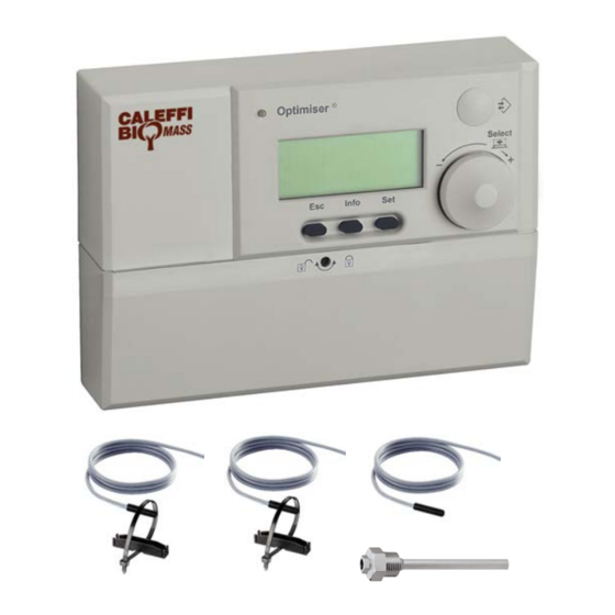
The OPTIMISER
digital regulator code 152200 makes it
®
possible to combine a solid fuel generator with another type
of generator already present in the heating system.
The digital regulator automatically manages the two
generators, receiving the signal from the probes and
activating the pumps, the motorized diverter valves in the
system, according to the heating circuit needs.
Depending on the type and quantity of installed probes, the
regulator supports the following system solutions:
- heating;
- production of domestic hot water by means of storage or
instantaneous with plate heat exchanger;
- management of inertial water storage in parallel on the
heating circuit or alternatively management of an
independent solar system and direct inertial water
storage.
INST LL TION ND COMMISSIONING M NU L
CONTENTS
Function
1
18146.01EN
1522 series
1
2
2
4
4
5
7
Advertisement

Related Manuals for CALEFFI BIOMASS OPTIMISER 1522 Series


Summary of Contents for CALEFFI BIOMASS OPTIMISER 1522 Series
-
Page 1: Table Of Contents
www.c leffi.com 18146.01EN OPTIMISER ® digital regulator for heating systems with solid fuel generator © opyright 2014 alef fi 1522 series INST LL TION ND COMMISSIONING M NU L CONTENTS Function Warnings Technical data Display and commands General functions vailable programs Hydraulic diagrams of programs Function The OPTIMISER... -
Page 2: Warnings
WARNINGS The following instructions must be read and understood before installing, commissioning and maintaining the regulator. The safety symbol is used in this manual to draw attention to the relative safety instructions. The meaning of this symbol is as follows: CAUTION! YOUR SAFETY IS INVOLVED. - Page 3 NTC probes* resistance table: for solid fuel generator flow, domestic water storage, domestic heat exchanger, inertial water storage in parallel on the heating system, solar water storage. °C °C °C °C °C °C °C 14616 6164 2852 1430 13211 ±0 5634 2632 1331...
-
Page 4: Display And Commands
Display and commands General functions Display The regulator is equipped with a display to read and program the Optimiser control parameters, such as cut-in temperatures, function activation delay times, thermal disinfection programs, solar system control, etc. All the system’s functional parameters can be configured to match individual requirements by means of the “Select”... -
Page 5: Vailable Programs
Programs 1,2 and 3 (not listed in the table but however available) are functionally equivalent to programs 7,8 and 9 respectively but without thermal solar components. For specific setting (dipswitches and probes to be used) please see instruction sheet 28169 (www.caleffi.com). - Page 6 *Operating logic of program “management of inertial water storage in parallel on the heating system”. In accordance with construction and system regulations or depending on system management requirements it may be necessary to use an inertial water storage on the heating system. The regulator is supplied as standard with the parameters and probes required to manage a heating system with inertial water storage in parallel on the heating system.
-
Page 7: Hydraulic Diagrams Of Programs
The inertial water storage in parallel is managed in accordance with the logic described on page 6. By means of diverter valve V5 (not supplied in the pack, e.g.: Caleffi 6443..3BY series + relay box code F29525) the regulator manages all phases of loading and unloading of the water storage, which is kept closed only if the gas boiler has been activated. - Page 8 The inertial water storage in parallel is managed in accordance with the logic described on Sun. 10-12 page 6. By means of diverter valve V5 (not supplied in the pack, e.g.: Caleffi 6443..3BY series Mon. and Wed. + relay box code F29525) the regulator manages all phases of loading and unloading of the water storage, which is kept closed only if the gas boiler has been activated.
- Page 9 The inertial water storage in parallel is managed in accordance with the logic described on page 6. By means of diverter valve V5 (not supplied in the pack, e.g.: Caleffi 6443..3BY series + relay box code F29525) the regulator manages all phases of loading and unloading of the water storage, which is kept closed only if the gas boiler has been activated.
- Page 10 Program 7 (software code PR86) Heating with direct inertial water storage with tank-in-tank domestic hot water production, solar system 1 2 3 4 Number of probes utilised: 3 Probe S1 located on solid fuel generator flow Probe Sol1 (not supplied in the pack) located on the solar collector Probe Sol2 located on the tank-in-tank water storage Sol 1 Psol...
- Page 11 Program 8 (software code PR87) Heating with direct inertial water storage, domestic hot water production with storage integrated with 1 2 3 4 solar system Number of probes utilised: 4 Probe S1 located on the direct inertial water storage flow pipe to the secondary circuits Probe S2 (pocket not supplied in the pack) located on the domestic water storage Probe Sol1 (not supplied in the pack) located on the solar collector Probe Sol2 located on the domestic water storage...
- Page 12 Program 9 (software code PR88) Heating with direct inertial water storage integrated with solar system, instantaneous domestic hot 1 2 3 4 water production Number of probes utilised: 4 Probe S1 located on the direct inertial water storage flow pipe to the secondary circuits Probe S3 located on domestic heat exchanger outlet Probe Sol1 (not supplied in the pack) located on the solar collector Probe Sol2 located on the direct inertial water storage...
Need help?
Do you have a question about the BIOMASS OPTIMISER 1522 Series and is the answer not in the manual?
Questions and answers