Table of Contents
Advertisement
Quick Links
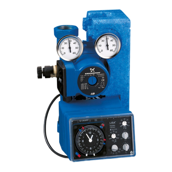
Temperature regulating unit
for heating and cooling
series 152
Product range
Code 152650
Temperature regulating unit for heating and cooling with pump UPS 25-60
Code 152651
Temperature regulating unit for heating and cooling with pump UPS 25-80
Code 151000
Room thermostat and indoor sensor
Technical specification
- Materials: - body:
- hydraulic seals:
- insulation shell:
- Mixing valve:
- Medium:
- Max percentage of glycol:
- Working temperature range:
- Max working pressure:
- By-pass regulating range:
- Thermometer scale:
- Primary and secondary circuit connections:
- Servomotor: electric supply:
rating:
cycle time:
torque:
- Grundfos pump:
cod. 152650
cod. 152651
- Max ambient relative humidity:
- Ambient temperature:
- Protection class:
Function
The temperature regulating unit is designed to guarantee the
correct contribution of heating energy required by the user, by
measuring the outside and room temperature values to regulate the
correct system flow temperature for either heating or cooling.
It is supplied complete with:
4-way mixing valve, servomotor, pump, flow temperature sensor,
outside temperature sensor, system temperature return sensor,
cooling surface humidity control sensor, temperature controller, flow
and return thermometers, unions for connecting to the primary and
secondary circuits, with preformed shell insulation.
The unit is designed for connection for remote data transmission.
This unit solves the problems of installation of regulating
components in modern small and medium-sized systems, due to its
compact size and ease of use.
The unit is factory set for use with underfloor heating systems.
Head available at regulating unit connections
grey cast iron GG19
H (m w.g.)
EPDM
6
PPM
5
4-way
4
water, glycol solutions
30%
3
5÷60°C
2
6 bar
1
0,05÷0,5 bar
0÷60°C
0
0
1" F with union
230V 50 Hz
10 VA
240 s
Power consumption
10 N·m
model UPS 25-60
Speed
model UPS 25-80
95%
0÷40°C
IP 42
UPS 25-60
code 152650
3
2
1
1
2
3
4
5
6
Q (m
3
/h)
P
n
I
(A)
(W)
(rpm)
3
0,45
100
1800
2
0,30
65
1100
1
0,17
35
700
CALEFFI
01088/03 GB
H (m w.g.)
6
UPS 25-80
code 152651
5
4
3
3
2
2
1
1
0
0
1
2
3
4
5
6
Q (m
3
/h)
P
n
I
Speed
(A)
(W)
(rpm)
3
1,13
250
2450
2
1,04
220
1500
1
0,69
140
1000
Advertisement
Table of Contents

Related Manuals for CALEFFI 152 Series


Summary of Contents for CALEFFI 152 Series
- Page 1 Temperature regulating unit for heating and cooling CALEFFI series 152 01088/03 GB Function The temperature regulating unit is designed to guarantee the correct contribution of heating energy required by the user, by measuring the outside and room temperature values to regulate the correct system flow temperature for either heating or cooling.
- Page 2 Dimensions CALEFFI WATCH -25% +25% -50% Code 152650/651 1" Characteristic components Hydraulic diagram SYSTEM SYSTEM 4-way mixing valve RETURN FLOW Servomotor Pump Automatic by-pass CALEFFI Differential by-pass WATCH -25% +25% Thermometer -50% BOILER FLOW FROM Temperature controller RETURN BOILER CALEFFI CALEFFI 01 4-way mixing valve.
- Page 3 The front panel of the controller shows the following functions: 10) Start or stop cooling selector. If the outside temperature is higher than the set value, the cooling function is activated. The LED is lit when there is a risk of condensation forming Factory setting: 24°C.
- Page 4 Correction selector for comfort mode. 11) Printed circuit board Range of adjustment from -25% to +25%. Factory setting: correction = 0%. The surface of the printed circuit board (PCB) identifies the following The selector determines a parallel displacement of the functions: characteristic curve according to the new percentage value selected in the comfort range (red indicator).
- Page 5 Selector for minimum flow temperature at heating start-up If various zones at risk of condensation are to be controlled, the (Tmin Y). humidity sensor must be connected to a suitable interface kit Adjustable from 20°C to 40°C. (transformer, converter and humidity sensor). Up to 12 converters Factory setting: 20°C.
- Page 6 Boiler circuit open Chiller circuit open The maximum heat energy that the panel can produce in relation with the climate values recorded, can be reached by controlling the below outlined parameters. CALEFFI WATCH -25% +25% -50% - Minimum flow temperature on the characteristic curve, which can be selected through the microswitch (point 4 on the back panel).
- Page 7 The difference between the actual room temperature measured by the thermostat and the set temperature produces an amplified CALEFFI effect in relation to that produced by a similar variation in the WATCH -25%...
- Page 8 We reserve the right to change our products and their relevant technical data, contained in this publication, at any time and without prior notice. CALEFFI CALEFFI S.P.A. · I · 28010 FONTANETO D’AGOGNA (NO) · S.R. 229, N.25 · TEL.INT. +39 0322 8491 R.A. · FAX +39 0322 863723 · Http://www.caleffi.com · E-mail: info@caleffi.it ·...
Need help?
Do you have a question about the 152 Series and is the answer not in the manual?
Questions and answers