Table of Contents
Advertisement
Quick Links
161010
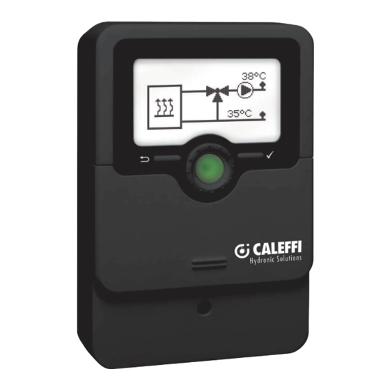
Digital controller with system representation
Heating controller
Manual for the
specialised craftsman
Installation
Operation
Troubleshooting
en
Manual
Thank you for buying this product.
Please read this manual carefully to get the best performance from this unit. Please keep this manual safe.
Please read this manual carefully to get the best performance from this unit. Please keep this manual safe.
Advertisement
Table of Contents

Related Manuals for CALEFFI 161010


Summary of Contents for CALEFFI 161010
- Page 1 161010 Digital controller with system representation Heating controller Manual for the specialised craftsman Installation Operation Troubleshooting Manual Thank you for buying this product. Please read this manual carefully to get the best performance from this unit. Please keep this manual safe.
- Page 2 Safety advice Target group Please pay attention to the following safety advice in order to avoid danger and These instructions are exclusively addressed to authorised skilled personnel. damage to people and property. Only qualified electricians should carry out electrical works. Initial installation must be effected by the system owner or qualified personnel Instructions named by the system owner.
-
Page 3: Table Of Contents
Heating controllers The heating controller is designed for controlling single-circuit heating circuits and / or single-circuit cooling systems. Contents Overview ....................4 Installation ................... 5 2.1 Mounting .........................5 2.2 Electrical connection ....................5 Operation and function ..............6 3.1 Buttons and adjustment dial ..................6 3.2 Adjustment values and user code ................6 3.3 Control LED ........................7 Systems .................... -
Page 4: Overview
Overview Technical data Upper fastening Inputs: 3 inputs for Pt1000 temperature sensors, 1 Grundfos Direct Sensor™ (analogue), 1 input for a room thermostat, 1 input for a dew point switch, 1 poten- tial-free switch Outputs: 3 semiconductor relays, 1 potential-free extra-low voltage relay, 1 PWM output PWM frequency: 512 Hz PWM voltage: 10.8 V... -
Page 5: Installation
Installation 2.2 Electrical connection 2.1 Mounting WARNING! Electric shock! Upon opening the housing, live parts are exposed! WARNING! Electric shock! Î Always disconnect the device from power supply Upon opening the housing, live parts are exposed! before opening the housing! Î... -
Page 6: Operation And Function
Heiskampstr. 10 The controller is operated via 2 buttons and 1 adjustment dial (Lightwheel ) below ® D-45527 Hattingen 161010 the display: IP 20 Left button (⟲) - escape button for changing into the previous menu Sensors R4|1 (1) A 30V R1-R3|1 (1) A 240 V~ Right button (✓) - confi rming / selecting... -
Page 7: Control Led
3.3 Control LED If the room thermostat demands heat, the pump (R1) starts and R4 is energised for the heating demand. The temperature at S2 is monitored. The mixer is controlled so The controller is equipped with a multicolour LED in the centre of the Lightwheel ®... - Page 8 = demand contact of the heat generator (potential-free extra-low voltage Factory Range Description relay). If the voltage at the contact used is higher than 30 V, use the setting auxiliary terminals at the 230 V side for the mixer. Start Start, Cancelled Activation / Deactivation slab drying PWM 1...
- Page 9 System 2 (weather-compensated heating – flow temperature controlled cooling) If the Condensation option is activated, the controller monitors a dew point switch. If the dew point switch triggers an alarm, cooling stops and the warning symbol is indicated. Terminal allocation = outdoor temperature sensor = heating circuit flow S3/RTA12 = return sensor or remote control (optional)
-
Page 10: Indications, Functions And Options
Indications, functions and options Factory Range Description setting Note: Corr.tMixer 90 s 5 … 300 s Surplus mixer runtime when the mixer is The display and adjustment channels as well as the adjustment ranges de- closing pend on the system selected, the functions and options as well as on the tPLAY 1 …... -
Page 11: Display Values
Cooling mode in system 1 5.3 Warning messages The room thermostat demands cold. TMax is exceeded. Heating mode in system 2 Pressure has fallen below PMin. The room thermostat demands heat, the outdoor temperature is indicated. Cooling mode in system 2 Sensor fault warning message The room thermostat demands cold, the outdoor temperature is indicated. -
Page 12: Configuration
5.4 Confi guration In order to access the adjustment values from the home screen, press the right button (✓) for approx. 3 s and enter the user code (see page 6). Tset Set fl ow temperature TFcalculated Heat demand-based set fl ow temperature calculation option TFset Display value: calculated set fl ow temperature TMin... - Page 13 TMin Remote control Minimum temperature heating circuit Remote control option TMax Cooling Maximum temperature heating circuit option Cooling option TMax TCool Maximum temperature heating circuit Cooling temperature tLimit Condensat. Time for which the calculated set fl ow temperature is to be used Dew point switch (DPS) option...
- Page 14 Chiller on Corr.tMixer Cooling demand on, if the dew point switch detects condensation (only if Conden- Surplus mixer runtime when the mixer is closing sation = Yes) tPLAY Pressure Mixer control time for change of fl ow direction Low pressure monitoring option Block.
- Page 15 Slab drying Rise time Rise duration Slab drying submenu tBacking TStart TMax holding time Start temperature Start TMax Activation / Deactivation of the slab drying Holding temperature Language Rise Selection of the menu language Rise value...
-
Page 16: Balance Values
Reset Min. press., Max. press. Reset to factory settings Minimum and maximum pressure The balance values can be set back to zero. In order to reset a value, proceed as 5.5 Balance values follows: Operation Î Select the desired value and press the right button (✓). Operating hours counter Does the security enquiry Delete? appear? Î... - Page 17 Man. 1 (4) Manual mode of the relays 1 and 4 For control and service work, the operating mode of the relays can be manually adjusted. • On Relay on • Auto Relay in automatic operation • Off Relay off Man.
-
Page 18: Application Example
Manufactured 100 ... 240 V Heating circuit flow by RESOL - TYPE SLT 50-60 Hz Heiskampstr. 10 D-45527 Hattingen 161010 Return sensor (optional) IP 20 Sensors R4|1 (1) A 30V R1-R3|1 (1) A 240 V~ Room thermostat Dew point switch (optional) Boiler demand when voltage <... - Page 19 Short circuit or line break. Disconnected temperature sensors can be checked with an ohmmeter. Please check if the resistance values correspond with the table. °C Ω °C Ω Pt1000 Pt1000 1213 1232 1000 1252 1019 1271 1039 1290 1058 1309 1078 1328 1097...
- Page 20 Distributed by Distributed by: Caleffi S.p.A. S.R. 229, no 25, IT-28010 Fontaneto d’Agogna (NO) © All contents of this document are protected by copyright.
Need help?
Do you have a question about the 161010 and is the answer not in the manual?
Questions and answers