Table of Contents
Advertisement
Quick Links
AN2018-35 EVAL-M1-IM818-A user guide
EVAL-M1-IM818-A user guide
Modular application design kit (MADK) of IM818
IM818-XCC, IM818-MCC, IM818-LCC
About this document
Scope and purpose
This application note provides an overview of the evaluation board EVAL-M1-IM818-A including its main
features, key data, pin assignments and mechanical dimensions.
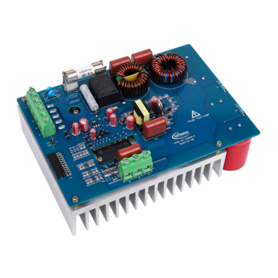
EVAL-M1-IM818-A is a complete evaluation board including a 3-phase CIPOS™ Maxi Intelligent Power Module
(IPM) for motor drive application. In combination with control-boards equipped with the M1 20pin interface
connector, like EVAL-M1-101T, it features and demonstrates Infineon's CIPOS™ Maxi IPM technology for motor
drive.
The evaluation board EVAL-M1-IM818-A was developed to support customers during their first steps designing
applications with CIPOS™ Maxi IPM. It includes IM818-SCC,IM818-MCC and IM818-LCC. They are focusing on
AC380V input, and 1~4.8 kW output application.
The default of CIPOS™ Maxi IPM in this board is IM818-MCC which has 3-phase inverter with 1200 V
TRENCHSTOP™ IGBTs and Emitter Controlled diodes are combined with an optimized 6-channel SOI gate
driver. It is optimized to industrial applications like Ventilation and Air Conditioning and motor drive.
All CIPOS™ Maxi IPM IM818 series can directly replace the test on the board.
Intended audience
This user guide is intended for all technical specialists who know motor control, middle- and low-power
electronics converters. The board is intended to be used under laboratory conditions.
Evaluation Board
This board will be used during design in, for evaluation and measurement of characteristics, and proof of data
sheet specifications.
Note:
PCB and auxiliary circuits are NOT optimized for final customer design.
User guide
Please read the Important notice and the Safety precautions and the Warnings
Revision 1.4
www.infineon.com
page 1 of 35
2021-09-10
Advertisement
Table of Contents

Related Manuals for Infineon EVAL-M1-IM818-A


Summary of Contents for Infineon EVAL-M1-IM818-A
-
Page 1: About This Document
About this document Scope and purpose This application note provides an overview of the evaluation board EVAL-M1-IM818-A including its main features, key data, pin assignments and mechanical dimensions. EVAL-M1-IM818-A is a complete evaluation board including a 3-phase CIPOS™ Maxi Intelligent Power Module (IPM) for motor drive application. -
Page 2: Important Notice
Boards provided by Infineon Technologies. The design of the Evaluation Boards and Reference Boards has been tested by Infineon Technologies only as described in this document. The design is not qualified in terms of safety requirements, manufacturing and operation over the entire operating temperature range or lifetime. -
Page 3: Safety Precautions
Failure to remove all packing materials that are unnecessary for system installation may result in overheating or abnormal operating conditions. Caution: EVAL-M1-IM818-A is evaluation board of IM818 series IPM and it is only default for IM818-MCC. Don’t guarantee hardware change. User guide 3 of 35 Revision 1.4... -
Page 4: Table Of Contents
NTC thermistor characteristics and over-heat protection calculation .......... 20 2.6.5 EMI filter and soft power up circuit....................22 Schematic for EMI filter and AC/DC section of the EVAL-M1-IM818-A evaluation board ....23 Inverter section using CIPOS™ Maxi IPM ....................23 Auxiliary power supply .......................... 24 Layout .............................. -
Page 5: The Board At A Glance
The board at a glance The board at a glance The EVAL-M1-IM818-A evaluation board is a part of the iMOTION™ Modular Application Design Kit for drives (iMOTION™ MADK). The MADK platform is intended to use various power stages with different control boards. These boards can easily be interfaced through the iMOTION™... -
Page 6: Delivery Content
BAS3005A02VH6327XTSA1 Block diagram The block diagram of the EVAL-M1-IM818-A is depicted in Figure 2. This evaluation board includes a DC EMI filter, soft power up circuit, 20-pin iMOTION™ MADK-M1 interface connector, an auxiliary power supply to provide 15 V and 3.3 V, and the CIPOS™ Maxi IPM IM818-MCC. -
Page 7: Main Features
The board at a glance Main features EVAL-M1-IM818-A is an evaluation board for motor drive applications based on a 3-phase IPM. Combined with one of the available MADK control board options, it demonstrates Infineon's IPM technology for motor drives. The kit demonstrates Infineon’s IPM technology for motor drives. - Page 8 EVAL-M1-IM818-A user guide Evaluation power board with MADK M1 connector The board at a glance Parameter Symbol Conditions Value Unit Output Maximum output Power out Input 380V =6 kHz, 1600 IM818-SCC power (3 phase) Ta=25°C, TC=100°C, 2400 IM818-MCC Natural convection...
-
Page 9: System And Functional Description
System and functional description System and functional description Commissioning EVAL-M1-IM818-A evaluation board is a power system without control part. It has a M1 connector with control input. Figure 3 is example system setup with Infineon iMOTION control board EVAL-M1-101T. This is motor control engine (MCE) evaluation board. -
Page 10: Setting Up The System
Refer to user manual for iMOTION™ MADK control board such as (EVAL-M1-101T), MCEWizard and MCEDesigner documentation for more information. Figure 3 shows the system connection using EVAL-M1-IM818-A and control board (used control board EVAL-M1- 101T for example). -
Page 11: Mcewizard Setup Overview
“Welcome Page” for MCEWizard, where the MADK control board or power board can be selected through the pull-down list. Infineon keeps releasing new MADK controller and power boards. Therefore, it could happen that some of the newest power boards are not pre-configured in the MCEWizard tool and cannot be selected through the pull-down menu. - Page 12 EVAL-M1-IM818-A user guide Evaluation power board with MADK M1 connector System and functional description MCEWizard setup overview table Table 4 Page Parameter Value Comment Welcome Page Control Board Selecting EVAL-M1-101T for example Welcome Page Power Board Selecting EVAL-M1-IM818-A If no, select similar...
-
Page 13: Mcedesigner Setup Overview
EVAL-M1-IM818-A user guide Evaluation power board with MADK M1 connector System and functional description 2.4.2 MCEDesigner setup overview After installing MCEDesigner installer, there is a shortcut for MCEDesigner on Windows desktop. Double click the shortcut to open MCEDesigner and then open “IMC101T_xx.irc” file as shown in Table 4. -
Page 14: Description Of The Functional Blocks
(http://www.infineon.com/imotion-software). Description of the functional blocks This chapter covers the hardware design of the EVAL-M1-IM818-A in more detail. It’s includes the functional groups of this power board and interface definition. Engineers can use this board to evaluate the performance easily. - Page 15 9. Rectifier bridge DB Functional groups of the EVAL-M1-IM818-A evaluation board’s top side Figure 9 General information about the connectors of the EVAL-M1-IM818-A evaluation board is reported. Table 5 includes the details of the AC line connector J1. J1- AC Line connector Table 5 S.
-
Page 16: Hardware Description Of Eval-M1-Im818-A
Connected to motor phase W Hardware description of EVAL-M1-IM818-A To meet individual customer requirements and make the EVAL-M1-IM818-A evaluation board a basis for development or modification, all necessary technical data like schematics, layout and components are included in this chapter. -
Page 17: Dc Bus Measurement And Mcewizard Configuration
DC bus sense resistor on EVAL-M1-IM818-A evaluation board Figure 10 The pull-down resistor R8 of 1 MΩ referred to ground is inserted on the EVAL-M1-IM818-A evaluation board to prevent the high BUS voltage +BUS directly connecting to the connector J3. And a pull-down resistor of 13.3 kΩ... -
Page 18: Motor External Current Feedback Configuration And Calculation
+ �� ��ℎ ��ℎ Based on this calculation, the current input for the MADK combination of EVAL-M1-101T and EVAL-M1-IM818-A is 20.83 mV/A. Please use same procedure to calculate the current input for other combinations of MADK boards and enter it... -
Page 19: Itrip And Gk Setup
EVAL-M1-IM818-A user guide Evaluation power board with MADK M1 connector System and functional description Current feedback configuration in MCEWizard for EVAL-M1-101T and EVAL-M1-IM818-A Figure 14 2.6.3 ITRIP and GK setup 2.6.3.1 ITRIP setup Over-current protection circuit and ITRIP signal Figure 15 IM818 series provides an over-current detection function by connecting the ITRIP input with the shunt current feedback. -
Page 20: Pwm Shut Down And Gk Output
EVAL-M1-IM818-A user guide Evaluation power board with MADK M1 connector System and functional description 2.6.3.2 PWM shut down and GK output When over-current is detected, the ITRIP voltage is over the threshold value, then C30 will be discharged (GK is open drain), and GK drops to “0”. This GK sends signal to control board via J3. GK “0” status is continuous for about 150 µs. - Page 21 EVAL-M1-IM818-A user guide Evaluation power board with MADK M1 connector System and functional description VTH output vs NTC to EVAL-M1-101T: Table 8 Temperature (°C) NTC (kΩ) VTH (V) 29.97 2.839 20.51 2.667 14.31 2.462 10.16 2.231 7.345 1.984 5.388 1.733 4.009...
-
Page 22: Emi Filter And Soft Power Up Circuit
27 0.5W 220uH 7.1A DCBUS ZTPV-25 30A1000V 10W100ohm 2200pF 4kV 104 1000V 2200pF 4kV 2mH 10A 104 1000V CON7 GUO40-12NO1 GND1 Current feedback configuration in MCEWizard for EVAL-M1-101T and EVAL-M1-IM818-A Figure 21 User guide 22 of 35 Revision 1.4 2021-09-10... -
Page 23: Schematic For Emi Filter And Ac/Dc Section Of The Eval-M1-Im818-A Evaluation Board
Inverter section using CIPOS™ Maxi IPM Figure 22 shows the inverter section of the EVAL-M1-IM818-A that is implemented using the CIPOS™ Maxi IPM. The module includes an optimized SOI gate driver and three phase inverter with 1200 V TRENCHSTOP™ IGBTs and Emitter Controlled diodes. -
Page 24: Auxiliary Power Supply
Auxiliary power supply Figure 23 depicts the schematic of the auxiliary power supply of the EVAL-M1-IM818-A board. The circuit includes the ICE5QSAG that is used to generate 15 V directly from the DC bus. VCC is connected to the gate drivers inside the CIPOS™... -
Page 25: Layout
EVAL-M1-IM818-A user guide Evaluation power board with MADK M1 connector Schematic for EMI filter and AC/DC section of the EVAL-M1-IM818-A evaluation board Layout The layout of this board can be used for different voltage or power classes. The PCB has two electrical layers with 35 µm copper by default and its size is 197 mm ×... - Page 26 EVAL-M1-IM818-A user guide Evaluation power board with MADK M1 connector Schematic for EMI filter and AC/DC section of the EVAL-M1-IM818-A evaluation board The top layer routing of the PCB is provided in Figure 26. Top layer routing of the EVAL-M1-IM818-A Figure 26 Figure 27 illustrates the bottom layer routing of the PCB.
-
Page 27: Bill Of Material
Schematic for EMI filter and AC/DC section of the EVAL-M1-IM818-A evaluation board Bill of material The complete bill of material is available on the download section of the Infineon homepage. A log-in is required to download this material. Table 9 provides the complete bill of materials of the evaluation board. -
Page 28: System Performance
For any re-install, it is necessary to clean the thermal conductive silicone grease and coating it again. Test results for output ability In order to test the total power capability of EVAL-M1-IM818-A, the IPM case temperature is tested with different input and output currents. -
Page 29: Test Range
EVAL-M1-IM818-A user guide Evaluation power board with MADK M1 connector System performance Infrared camera image for IPM temperature test Figure 28 Test range Figure 29 is IM818-MCC output ability at different PWM frequency and power input, which are performed under... - Page 30 EVAL-M1-IM818-A user guide Evaluation power board with MADK M1 connector System performance Figure 30 is IM818-LCC output ability at different PWM frequency and power input, which are performed under the following conditions: IM818-LCC DC400V 6kHz IM818-LCC DC700V 6kHz IM818-LCC DC400V 20kHz...
-
Page 31: Test Results Of Typical Waveform
Evaluation power board with MADK M1 connector System performance Test results of typical waveform Figure 32 is typical current waveform of a sinusoidal brushless motor driven by the EVAL-M1-IM818-A and EVAL- M1-101T with iMOTIONTM software. and I current waveform. It is IM818-MCC work on AC380V input, PWM=6kHz, motor drive on... - Page 32 EVAL-M1-IM818-A user guide Evaluation power board with MADK M1 connector System performance According to Fourier expansion equation, PWM square wave can be regarded as composed of several sine waves with multiple frequencies and different initial phase angles. Changing the slope of square wave, the high frequency harmonic components are reduced.
-
Page 33: References And Appendices
Meaning Conformité Européenne Electromagnetic interference Underwriters Laboratories References Datasheet of Infineon CIPOS™ Maxi IM818, that is available for download on Infineon’s website : https://www.infineon.com/dgdl/Infineon-IM818-MCC-DataSheet-v02_02- EN.pdf?fileId=5546d46265f064ff0165f9e91e3c2e9e Application Note AN2020-14 CIPOS Maxi Technical Description, that is available for download on Infineon’s website: https://www.infineon.com/dgdl/Infineon-AN2020-14_Bootstrap_circuit_design_for_the_CIPOS_IPM_series-... -
Page 34: Revision History
EVAL-M1-IM818-A user guide Modular application design kit (MADK) of IM818 Revision history Revision history Document Date of release Description of changes version 2018-11-15 First release 2019-04-02 Change output power to 1500W and Current to 2.35 A. Optimization schematic 2021-03-03 Change current feedback sensing value to 20.83 mV/A... - Page 35 WARNINGS 81726 Munich, Germany Due to technical requirements products may contain dangerous substances. For information on the types in question please contact your nearest Infineon © 2021 Infineon Technologies AG. Technologies office. All Rights Reserved. Except as otherwise explicitly approved by Infineon...
Need help?
Do you have a question about the EVAL-M1-IM818-A and is the answer not in the manual?
Questions and answers