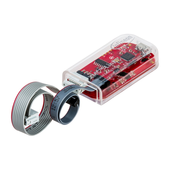
Table of Contents
Advertisement
Quick Links
Chipsmall Limited consists of a professional team with an average of over 10 year of expertise in the distribution
of electronic components. Based in Hongkong, we have already established firm and mutual-benefit business
relationships with customers from,Europe,America and south Asia,supplying obsolete and hard-to-find components
to meet their specific needs.
With the principle of "Quality Parts,Customers Priority,Honest Operation,and Considerate Service",our business
mainly focus on the distribution of electronic components. Line cards we deal with include
Microchip,ALPS,ROHM,Xilinx,Pulse,ON,Everlight and Freescale. Main products comprise
IC,Modules,Potentiometer,IC Socket,Relay,Connector.Our parts cover such applications as commercial,industrial,
and automotives areas.
We are looking forward to setting up business relationship with you and hope to provide you with the best service
and solution. Let us make a better world for our industry!
Contact us
Tel: +86-755-8981 8866 Fax: +86-755-8427 6832
Email & Skype: info@chipsmall.com Web: www.chipsmall.com
Address: A1208, Overseas Decoration Building, #122 Zhenhua RD., Futian, Shenzhen, China
Advertisement
Table of Contents

Subscribe to Our Youtube Channel
Summary of Contents for Infineon XMC Link
- Page 1 Chipsmall Limited consists of a professional team with an average of over 10 year of expertise in the distribution of electronic components. Based in Hongkong, we have already established firm and mutual-benefit business relationships with customers from,Europe,America and south Asia,supplying obsolete and hard-to-find components to meet their specific needs.
-
Page 2: Table Of Contents
Pinout of debug connectors ......................5 Power supply ............................6 Virtual COM Port (UART-to-USB Bridge) ....................6 Production data ..........................7 Schematics ..............................7 3.1.1 Differences in hardware versions ......................7 Components placement and geometry ....................9 List of material............................9 Revision history ..............................11 User's Manual R1.0 www.infineon.com 2015-12-11... -
Page 3: Introduction
ARM® ecosystem. Table 1 shows its specification. Table 1 XMC™ Link specification Supported Processor All Infineon Cortex®-M based XMC™ Microcontroller Dimensions 62 x 33 mm (without cables plugged in) Power PC side: 5 V via Micro-AB USB Connector Target side: 2.5 V –... -
Page 4: Getting Started
XMC™ Link Based on SEGGER J-Link Technology Table of contents XMC™ Link V1 12 MHz Debug Crystal GPIO CCU80 2.5V -5.5V RESET U0C0 8-pin XMC™ MCU Debug Connector XMC4200 RX/TX Micro JTAG U0C1 Micro- Isolating controller Device 10-pin Cortex™ U1C1 JTAG Debug Connector RX/TX... -
Page 5: Hardware Description
Known limitation XMC Link™ V1 has a minor known limitation which could occur only during programming the BMI of a XMC1000 device in ASC-BSL mode to another BMI mode. This limitation is solved in the PCB version V1.1. The version number is printed on the bottom side of the PCB below the USB connector. -
Page 6: Pinout Of Debug Connectors
XMC™ Link Based on SEGGER J-Link Technology Table of contents The common debug protocol supported by both connectors is Serial Wire Debug (SWD). Figure 3 provides an overview on all supported debug protocols and communication channels. XMC1000 Family XMC4000 Family 8-pin XMC™... -
Page 7: Power Supply
XMC™ Link Based on SEGGER J-Link Technology Table of contents Function XMC1000 Connection (Pin name) Power supply 2.5 V – 5.5 V (VDD) Ground (VSS) Ground (VSS) Power supply 2.5 V – 5.5 V (VDD) TX (PC-TX)) Transmissstion line of PC/laptop, receive line of XMC™ device (optional) RX (PC-RX) Receive line of PC/laptop, transmission line of of XMC™... -
Page 8: Production Data
XMC™ Link Based on SEGGER J-Link Technology Table of contents Production data This chapter covers schematics, board dimensions, component placement and the list of material. Schematics Figure 4 shows the schematics of XMC™ Link V1 in hardware version 1.1. 3.1.1 Differences in hardware versions In hardware version 1.1 compared to hardware version v1.0 (V1) the pull-down resistor R20 was added to the TX line. - Page 9 With respect to any examples or hints given herein, any typical values stated herein and/or any GND1 GND2 information regarding the application of the device, Infineon Technologies hereby disclaims any and all warranties 02.12.2015 12:23:57 and liabilities of any kind, including without limitation, warranties of non-infringement of intellectual property rights SI8652BB-B-IS1 of any third party.
-
Page 10: Components Placement And Geometry
4u7F 6.3V +-10% 0603 Capacitor X7R ZX62-AB-5PA Connector Micro USB AB SMD Hirose 1 12MHz 3.2x2.5 Crystal 12MHz 4Pad NX3225SA NDK ESD8V0L2B-03L TSLP-3-1 Diode Protection Infineon BLM18PG600SN1D 0603 Ferrite Bead 60R 500mA Murata SI8652BB-B-IS1 NB-SOIC-16 U3, U6 Isolation IC LSQ971-Z LED-GN 0603... - Page 11 1M 1% 0603 Resistor 22R 1% 0402 R3, R5 Resistor 4k7 1% 0402 Resistor 510R 1% 0402 Resistor 680R 1% 0603 Resistor R1, R2 no ass. 0R 0603 Resistor IFX54441LDV33 PG-TSON-10 Voltage Regulator 3.3 V Infineon User's Manual R1.0 2015-12-11...
-
Page 12: Revision History
XMC™ Link Based on SEGGER J-Link Technology Revision history Revision history Major changes since the last revision Page or reference Description of change User's Manual R1.0 2015-12-11... - Page 13 Do you have a question about this Except as otherwise explicitly approved by Infineon information given in this application note. Technologies in a written document signed by...

Need help?
Do you have a question about the XMC Link and is the answer not in the manual?
Questions and answers