
Related Manuals for Baker Hughes Consolidated 1982 Series


Summary of Contents for Baker Hughes Consolidated 1982 Series
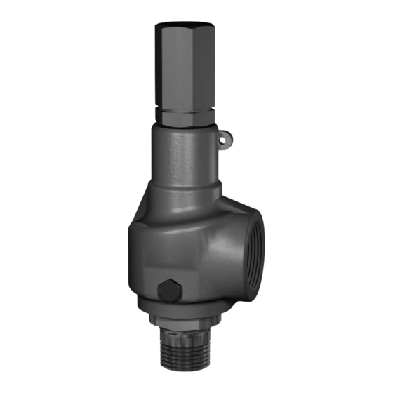
- Page 1 Consolidated ™ 1982 Series Safety Relief Valves Instruction Manual (Rev. B) Baker Hughes Data Classification : Public...
- Page 2 TO ASSIST IN THE INSTALLATION, TESTING, OPERATION, AND/OR MAINTENANCE OF THE EQUIPMENT DESCRIBED. THIS DOCUMENT SHALL NOT BE REPRODUCED IN WHOLE OR IN PART WITHOUT THE WRITTEN APPROVAL OF BAKER HUGHES. © 2020 Baker Hughes Company. All rights reserved. Baker Hughes...
- Page 3 Note: Multiply USCS value with conversion factor to get metric value. NOTICE! For any service questions not covered in this manual, please contact your local Green Tag™ Center (GTC). © 2020 Baker Hughes Company. All rights reserved. Consolidated 1982 Series Safety Relief Valve Manual...
-
Page 4: Table Of Contents
D. Lubricant ..............22 © 2020 Baker Hughes Company. All rights reserved. - Page 5 C. Maintenance Training ............26 © 2020 Baker Hughes Company. All rights reserved.
-
Page 6: Warranty Information
Unauthorized removal and/or breakage of this seal will negate our warranty. 1. Refer to the Baker Hughes Standard Terms of Sale for complete details on warranty and limitation of remedy and liability. Removal or breakage of seal will negate our warranty. -
Page 7: Safety Notice
(i.e., gloves, etc.) when personnel are in, or around, a valve work area. It is the responsibility of the purchaser or user of Baker Hughes valves/ equipment to adequately train all personnel who will be working with the involved product. -
Page 8: Product Safety Sign And Label System
© 2020 Baker Hughes Company. All rights reserved. Baker Hughes... -
Page 9: Safety Alerts
© 2020 Baker Hughes Company. All rights reserved. Consolidated 1982 Series Safety Relief Valve Manual... - Page 10 Read installation possible severe instructions before personal injury or installing valve(s). death. Wear necessary Always use protective equipment appropriate restoration to prevent procedures. possible injury © 2020 Baker Hughes Company. All rights reserved. Baker Hughes...
-
Page 11: Handling And Storage
Before start-up be sure all threaded points are tight and secure. Prevent dirt from entering the outlet or inlet port. © 2020 Baker Hughes Company. All rights reserved. Consolidated 1982 Series Safety Relief Valve Manual... -
Page 12: General Planning For Maintenance
A 12-month maintenance interval is recommended for general service conditions. For severe service applications, a 3 to 6 month inspection and testing interim may be more appropriate. The specific plant’s operating and service history will better determine this frequency. Baker Hughes encourages preventive maintenance. Occasionally, remachining may be necessary to extend the service life of a valve. Keep all parts for each valve separated to ensure replacement in the same valve. -
Page 13: Terminology For Pressure Relief Valves
“pop”. The difference between this start-to- open pressure and the set pressure is called “simmer”. Simmer is generally expressed as a percentage of set pressure. © 2020 Baker Hughes Company. All rights reserved. Consolidated 1982 Series Safety Relief Valve Manual... -
Page 14: Design Features And Nomenclature
However the valve cannot be used or safety valve or relief valve, depending on application. steam boilers or super heaters, but may be used on process steam. Safety relief valves are used on hundreds of different applications, including liquids and hydrocarbons © 2020 Baker Hughes Company. All rights reserved. Baker Hughes... -
Page 15: Consolidaed 1982 Series Safety Relief Valve
IX. Consolidated 1982 Series Safety Relief Valve A. Metal Seat Valve Part Nomenclature Base Inlet Flange (When Applicable) Bonnet Gasket Adjusting Ring Pin Gasket Adjusting Ring Pin Adjusting Ring Disc Assembly 6a Disc Collar 6b Disc Holder 6c Disc 6d Disc Retainer... - Page 16 IX. Consolidated 1982 Series Safety Relief Valve Part Nomenclature Plain Cap Release Locknut Release Nut Lever Pin Plain Lever Cap Screw Packed Cap Packed Lever O-Ring Bushing Cam Shaft Drive Stud Lever Gasket Sealing Plug Figure 2: Packed Cap Sealing Plug Gasket...
-
Page 17: Disassembly
2. Always use a fresh lap. If signs of wearing (out exceeded (Table 2), the base should be of flatness) is evident recondition the lap. discarded. 3. Apply a very thin layer of compound to the lap. This will prevent rounding off the edges of the seat. | 12 © 2020 Baker Hughes Company. All rights reserved. Consolidated 1982 Series Safety Relief Valve Manual... - Page 18 1.50 38.10 1.339 34.01 1.139 28.93 .025 0.64 1.909 48.49 .222 5.64 1.400 35.56 2.00 50.80 1.680 42.67 1.465 37.21 .025 0.64 2.449 62.20 .284 7.21 1.803 45.80 13 | © 2020 Baker Hughes Company. All rights reserved. Baker Hughes...
-
Page 19: Inspection And Part Replacement
45.59 .484 12.30 .098 2.49 ± .002 ± 0.05 1. Base to be discarded once D minimum is exceeded. Do not reestablish D. | 14 © 2020 Baker Hughes Company. All rights reserved. Consolidated 1982 Series Safety Relief Valve Manual... -
Page 20: Disc Retainer
Valve Size A max. 12.70 .722 18.34 19.05 .960 24.38 1.00 25.40 1.200 30.48 1.50 38.10 1.917 48.69 2.00 50.80 2.459 62.46 Figure 7: Bonnet Assembly (For Guide) 15 | © 2020 Baker Hughes Company. All rights reserved. Baker Hughes... -
Page 21: Adjusting Ring
.885 22.48 .902 22.91 0° 1.50 38.10 1.411 35.84 1.458 37.03 15° Figure 9: Adjusting Screw 2.00 50.80 1.815 46.10 1.871 47.52 0° | 16 © 2020 Baker Hughes Company. All rights reserved. Consolidated 1982 Series Safety Relief Valve Manual... -
Page 22: Reassembly
Holding bonnet and spindle (so that disc will not drop) install bonnet assembly to base. Tighten bonnet on base with strap wrench. 17 | © 2020 Baker Hughes Company. All rights reserved. Baker Hughes... -
Page 23: Setting And Testing
When using a test stand, the valve should be set to open at the cold differential set pressure as shown on the nameplate. The cold differential set pressure is the set pressure corrected to compensate for back pressure and/or operating temperature. | 18 © 2020 Baker Hughes Company. All rights reserved. Consolidated 1982 Series Safety Relief Valve Manual... -
Page 24: Test Equipment
Safety relief valves set at atmospheric temperatures and are to be used at higher temperatures should have the set pressure adjusted as per the appropriate multiplier listed in Table 5. Figure 10: Test Equipment 19 | © 2020 Baker Hughes Company. All rights reserved. Baker Hughes... - Page 25 The Table 5 can be used for set pressure adjustment of valves with operating temperatures from 251ºF 398.9 1.034 (121.7ºC) to 800ºF (426.7ºC). 426.7 1.038 | 20 © 2020 Baker Hughes Company. All rights reserved. Consolidated 1982 Series Safety Relief Valve Manual...
-
Page 26: Seat Leakage
/ 24 Hr. Liters/ 24 Hr. function properly. Consolidated Safety Relief Valves are furnished when so ordered with packed or plain lifting gears for hand popping. 0.60 16.99 21 | © 2020 Baker Hughes Company. All rights reserved. Baker Hughes... -
Page 27: Troubleshooting
Note: Ring Laps: One set of three (3) Ring Laps is recommended for each size to assure ample flat laps are available at all times. | 22 © 2020 Baker Hughes Company. All rights reserved. Consolidated 1982 Series Safety Relief Valve Manual... -
Page 28: Replacement Parts Planning
Class V - Parts Practically Never Requiring Replacement. 3. “Need Probability Coverage” is defined as the probable percent of total, uninterrupted operational time which can be expected by stocking predetermined valve component classifications. 23 | © 2020 Baker Hughes Company. All rights reserved. Baker Hughes... -
Page 29: Identification And Ordering Essentials
Consolidated valve products have been in use since 1879 • Baker Hughes has worldwide service • Baker Hughes has fast response availability for parts | 24 © 2020 Baker Hughes Company. All rights reserved. Consolidated 1982 Series Safety Relief Valve Manual... -
Page 30: Recommended Spare Parts
Release Locknut (used on packed or plain lever only) 1. Consult Spring Selection Chart before ordering Springs to determine actual quantities required in view of pressure setting potential in each spring range. 25 | © 2020 Baker Hughes Company. All rights reserved. Baker Hughes... -
Page 31: Manufacturer's Service, Repair And Training Program
XIX. Manufacturer’s Service, Repair and Training Program A. Field Service C. Maintenance Training Baker Hughes maintains one of the largest and most Rising costs of maintenance and repair in the utility competent network of field service technicians in the and process industries indicate the need for trained industry. - Page 32 Baker Hughes hereby disclaims any and all liability for any direct, indirect, consequential or special damages, claims for lost profits, or third party claims arising from the use of the information, whether a claim is asserted in contract, tort, or otherwise. Baker Hughes reserves the right to make changes in specifications and features shown herein, or discontinue the product described at any time without notice or obligation. Contact your Baker Hughes representative for the most current information. The Baker Hughes logo, Consolidated, and Green Tag are trademarks of Baker Hughes Company. Other company names...
Need help?
Do you have a question about the Consolidated 1982 Series and is the answer not in the manual?
Questions and answers