
Subscribe to Our Youtube Channel
Related Manuals for Baker Hughes Consolidated 2900-40 Series


Summary of Contents for Baker Hughes Consolidated 2900-40 Series
- Page 1 Consolidated ™ 2900-40 Series Pilot-Operated Safey Relief Valves Instruction Manual (Rev. D) Baker Hughes Data Classification : Public...
- Page 2 OPERATOR ARE STRICTLY LIMITED TO THOSE EXPRESSLY PROVIDED IN THE CONTRACT RELATING TO THE SUPPLY OF THE EQUIPMENT. NO ADDITIONAL REPRESENTATIONS OR WARRANTIES BY BAKER HUGHES REGARDING THE EQUIPMENT OR ITS USE ARE GIVEN OR IMPLIED BY THE ISSUE OF THESE INSTRUCTIONS.
- Page 3 Note: Multiply USCS value with conversion factor to get metric value. NOTICE! For valve configurations not listed in this manual, please contact your local Green Tag™ Center for assistance. © 2020 Baker Hughes Company. All rights reserved. Consolidated 2900-40 Series POSRV Instruction Manual...
-
Page 4: Table Of Contents
A. General Introduction ............................15 B. Main Valve Introduction .............................15 C. Pilot Valve Introduction ............................15 Consolidated 2900-40 Series Safety Relief Valves .....................16 A. 2900-40 Main Valve (Metal Seat) ........................16 B. 2900-40 Main Valve (Soft Seat) ........................17 C. 39PV Pilot Valve ..............................18 Operating Principles ..............................19... - Page 5 Troubleshooting ...............................58 XXII. 2900-40 Series POSRV Options ..........................59 A. Backflow Preventer ............................59 A.1 Disassembly Instructions ...........................59 A.2 Cleaning ..............................59 A.3 Parts Inspection ............................59 A.4 Reassembly Instructions ..........................59 © 2020 Baker Hughes Company. All rights reserved. Consolidated 2900-40 Series POSRV Instruction Manual...
- Page 6 Genuine Consolidated Parts ............................72 XXVI. Recommended Spare Parts..........................73-78 XXVII. Manufacture's Field Service, Repair, and Training Programs ................79 A. Field Service ..............................79 B. Repair Facilities ..............................79 C. Safety Relief Valve Maintenance Training ......................79 © 2020 Baker Hughes Company. All rights reserved. Baker Hughes...
-
Page 7: Product Safety Sign And Label System
© 2020 Baker Hughes Company. All rights reserved. Consolidated 2900-40 Series POSRV Instruction Manual... -
Page 8: Safety Alerts
7. WARNING: This valve product line is not intended for radioactive nuclear applications. Some valve products Manufactured by Baker Hughes may be used in radioactive environments. Consequently, prior to starting any operation in a radioactive environment, the proper “health physics” procedures should be followed, if applicable. - Page 9 Maintenance Manual, when correctly applied, will be effective. Wear necessary Always use appropriate protective equipment to restoration procedures. prevent possible injury © 2020 Baker Hughes Company. All rights reserved. Consolidated 2900-40 Series POSRV Instruction Manual...
-
Page 10: Safety Notice
Consequently, Baker Hughes has not undertaken any such broad evaluation and, thus, anyone who uses a procedure and/or tool, which is not recommended by Baker Hughes, or deviates from Baker Hughes's recommendations, must be thoroughly satisfied that neither personal safety, nor valve safety, will be jeopardized by the method and/or tools selected. -
Page 11: Warranty Information
Hughes Field Services are sealed to assure the customer of our guarantee against defective workmanship. Unauthorized removal and/or breakage of this seal will negate our warranty. Note: Refer to Baker Hughes’s Standard Terms of Sale for complete details on war- ranty and limitation of remedy and liability. -
Page 12: Terminology For Pilot Operated Safety Relief Valves
Consequently, for that metal temperature, it is the highest pressure at which the primary pressure POSRV is set to open. 12 | © 2020 Baker Hughes Company. All rights reserved. Baker Hughes... -
Page 13: Handling And Storage
Never attempt to lift the valve by anything other than the eyebolts. © 2020 Baker Hughes Company. All rights reserved. | 13 Consolidated 2900-40 Series POSRV Instruction Manual... -
Page 14: Pre-Installation And Installation Instructions
15-25 psi (1-1.5 bar). For pressures exceeding this limit, a Nitrogen bottle cleaning method used. (connected to the field test connector) precharged up to 97% of set pressure may be used. 14 | © 2020 Baker Hughes Company. All rights reserved. Baker Hughes... -
Page 15: Introduction
39PV37, SS Steam 51.78 3750 258.55 -20.0 262.8 Note: With the installation of the heat exchanger, temperature range may be expanded to 1200°F (648.9°C). © 2020 Baker Hughes Company. All rights reserved. | 15 Consolidated 2900-40 Series POSRV Instruction Manual... -
Page 16: Consolidated 2900-40 Series Safety Relief Valves
Disc Disc Retainer Disc Holder Guide Guide Gasket Guide Ring 1/2” NPT DRAIN Stud (Base) Nut (Base) Plug/Adaptor Plug/Adaptor Gasket Figure 1: 2900-40 Metal Seat Valve Construction Spring 16 | © 2020 Baker Hughes Company. All rights reserved. Baker Hughes... -
Page 17: 2900-40 Main Valve (Soft Seat)
Figure 2: 2900-40 Soft Seat Valve Construction Part Nomenclature Nozzle Disc Disc Retainer Disc Holder Guide O-Ring Retainer Lock Screw O-Ring Retainer O-Ring Seat Seal © 2020 Baker Hughes Company. All rights reserved. | 17 Consolidated 2900-40 Series POSRV Instruction Manual... -
Page 18: 39Pv Pilot Valve
Pipe Plug (Pilot Valve) Set Screw (Bonnet) Top Plate 1. Standard material is a filter plug. For HIGH PRESSURE special materials, vent assembly is supplied. Figure 3: 39PV Pilot Valve Construction 18 | © 2020 Baker Hughes Company. All rights reserved. Baker Hughes... -
Page 19: Operating Principles
Since the area of the top of the piston is larger than the area of the seating surface, the differential area results in a net downward force keeping the main valve tightly closed. Figure 4: Pilot Valve (Closed) © 2020 Baker Hughes Company. All rights reserved. | 19 Consolidated 2900-40 Series POSRV Instruction Manual... -
Page 20: Pv Valve Open (Relieving Position)
As the dome pressure equalizes with the inlet pressure, the downward force created by the differential areas of the piston and disc closes the main valve. Figure 5: Pilot Valve (Opened) 20 | © 2020 Baker Hughes Company. All rights reserved. Baker Hughes... -
Page 21: General Planning For Maintenance
Position the POSRVs for easy access and/or removal so that servicing can be properly performed. Ensure sufficient working space is provided around and above the valve. © 2020 Baker Hughes Company. All rights reserved. | 21 Consolidated 2900-40 Series POSRV Instruction Manual... -
Page 22: Inlet Piping
3% of the valve set pressure. P.D. P.D. P.D. P.D. Stop From Protected Equipment Valve Vessel Vessel Vessel Figure 6: Pressure Drop on the Inlet Piping 22 | © 2020 Baker Hughes Company. All rights reserved. Baker Hughes... -
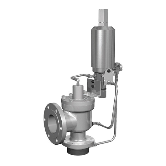
Page 23: Remote Sensing
ATTENTION!! Change in elevation between relief valve and source of sensing line may cause set pressure changes. Figure 8: Pilot Operated Safety Relief Valve © 2020 Baker Hughes Company. All rights reserved. | 23 Consolidated 2900-40 Series POSRV Instruction Manual... - Page 24 Figures 8 and 9. Figure 8 shows a Figure 9: POSRV with Heat Exchanger standard pilot operated relief valve. Figure 9 shows a pilot operated relief valve equipped with a heat exchanger. 24 | © 2020 Baker Hughes Company. All rights reserved. Baker Hughes...
-
Page 25: Disassembly Of The 2900-40 Posrv
If Main Valve Piston O-Ring or Spring Energize Seal is damaged, then Main Valve Piston may fall out of Cover Plate during disassembly. Remove pipe plug from Cover Plate. © 2020 Baker Hughes Company. All rights reserved. | 25 Consolidated 2900-40 Series POSRV Instruction Manual... - Page 26 XIII. Disassembly of the 2900-40 POSRV (Cont.) Figure 10: Metal Seat Valve Disassembly 26 | © 2020 Baker Hughes Company. All rights reserved. Baker Hughes...
- Page 27 Disc Retainer For “P” through “T” orifices, install the Disc Holder Removal Tool (Baker Hughes P/N 4464604) in the top of the Disc Holder as shown in Figure 14. Lift out and remove the Guide and Disc Holder. Remove the Lifting Thermodisc Tool from the top of the Disc Holder.
- Page 28 View From Side Nozzle Pipe Wrench 3 Jaw Chuck Nozzle Base Chuck Stand Figure 16: Loosening the Nozzle from the Base Figure 17: Removing the Nozzle from the Base 28 | © 2020 Baker Hughes Company. All rights reserved. Baker Hughes...
-
Page 29: Cleaning
Do not “sand blast” internal parts as it can reduce the dimensions of the parts. Follow recommendations for safe handling in the solvent's Material Safety Data Sheet and observe safe practices for any cleaning method © 2020 Baker Hughes Company. All rights reserved. | 29 Consolidated 2900-40 Series POSRV Instruction Manual... -
Page 30: Maintenance Instructions
Figure 18a: Metal Seat Nozzle Figure 18b: Soft Seat Nozzle 5° 45° 45° Nozzle Nozzle Bore Bore Figure 18: Main Valve Nozzle Critical Dimensions 30 | © 2020 Baker Hughes Company. All rights reserved. Baker Hughes... - Page 31 0.08 1. Do not remachine threaded areas of the nozzle to reestablish “D” dimension. Once “D” minimum is reached, replacement of nozzle is necessary. © 2020 Baker Hughes Company. All rights reserved. | 31 Consolidated 2900-40 Series POSRV Instruction Manual...
-
Page 32: Lapped Nozzle Seat Widths
Type A Lamp Assembly (Standard Molding Corp.), or equivalent. Figure 19a: Measuring Magnifier Figure 19b: Magnifier Details Measuring Magni er Nozzle Figure 19: Measuring Magnifier 32 | © 2020 Baker Hughes Company. All rights reserved. Baker Hughes... - Page 33 2. Not to exceed .070 ± .005" (1.78±0.13 mm). 20.75 55.16 .060 1.52 .070 1.78 55.23 Above Full Width 1.03 6.89 .050 1.27 .060 1.52 6.96 20.68 .060 1.52 .075 1.91 © 2020 Baker Hughes Company. All rights reserved. | 33 Consolidated 2900-40 Series POSRV Instruction Manual...
-
Page 34: Precautions And Hints For Lapping Seats
(Figure 21). The surfaces marked A and B must be running concentric. b. True up the nozzle so that the surfaces marked B and C run true within .001” (0.03 mm) on indicator (Figure 22). 34 | © 2020 Baker Hughes Company. All rights reserved. Baker Hughes... -
Page 35: Re-Machining The Disc Seat
The nozzle is now ready for lapping. Do not remachine a Thermodisc or O-Ring Retainer. d. When the minimum dimension H is reached, discard the nozzle. © 2020 Baker Hughes Company. All rights reserved. | 35 Consolidated 2900-40 Series POSRV Instruction Manual... - Page 36 (K-T Orifices Only) Type 2 .485 12.32 .015 0.38 .610 15.49 .015 0.38 .610 15.49 .015 0.38 .610 15.49 .015 0.38 .822 20.88 .015 0.38 Figure 24: Disc Inspection Areas 36 | © 2020 Baker Hughes Company. All rights reserved. Baker Hughes...
-
Page 37: Inspection And Part Replacement
2.315 58.80 2.315 58.80 2.315 58.80 b. If the dimension cannot be measured, replace the 2.315 58.80 2.315 58.80 Thermodisc. 2.315 58.80 2.315 58.80 © 2020 Baker Hughes Company. All rights reserved. | 37 Consolidated 2900-40 Series POSRV Instruction Manual... -
Page 38: O-Ring Seated Disc
“B” minimum and “E” minimum, indicated in Refer to Tables 20 for a list of recommended spare parts Table 8. and Table 21 for a list of O-Ring repair kits. 38 | © 2020 Baker Hughes Company. All rights reserved. Baker Hughes... -
Page 39: Reassembly Of 2900-40 Main Valve
1920 2603.17 1/4-28UNF ± 3 ± 0.3 1. DO NOT USE impact wrench on "D" through "K" orifice 1/4-28UNF ± 3 ± 0.3 Nozzles. © 2020 Baker Hughes Company. All rights reserved. | 39 Consolidated 2900-40 Series POSRV Instruction Manual... - Page 40 Main Valve Piston is even with the bottom of the Cover Plate. 14. Install 1/4” MNPT pipe plug into Cover Plate where dome line connects. 40 | © 2020 Baker Hughes Company. All rights reserved. Baker Hughes...
- Page 41 Holes 19. The Main Valve is ready to receive the pilot and finished assembly. Figure 29: Bolt Tightening Patterns © 2020 Baker Hughes Company. All rights reserved. | 41 Consolidated 2900-40 Series POSRV Instruction Manual...
- Page 42 — — — — — — — — — — — — — — — — — — — — — — — — — — — — 42 | © 2020 Baker Hughes Company. All rights reserved. Baker Hughes...
-
Page 43: Disassembly Of Pilot Valve
See the 1 - Spring Seal (Insert) solvent’s Material Safety Data Sheet for safe handling 1 - O-Ring (Insert) recommendations and equipment. © 2020 Baker Hughes Company. All rights reserved. | 43 Consolidated 2900-40 Series POSRV Instruction Manual... - Page 44 XVII. Disassembly of Pilot Valve (Cont.) 39PV37 Figure 30: 39PV07/37 Disassembly 44 | © 2020 Baker Hughes Company. All rights reserved. Baker Hughes...
- Page 45 Follow recommendations for safe handling in the solvent's Material Safety Data Sheet and observe safe practices for any cleaning method Figure 31: Lifting Lever Disassembly © 2020 Baker Hughes Company. All rights reserved. | 45 Consolidated 2900-40 Series POSRV Instruction Manual...
-
Page 46: Part Inspection Of Pilot Valve
Also, check for galling of threads. Adjuster Bottom: Galling or excessive wear on the inside diameter that guides the Main Piston. Check for any corrosion or pitting. Also, check for galling of threads. 46 | © 2020 Baker Hughes Company. All rights reserved. Baker Hughes... -
Page 47: Reassembly Of Pilot Valve
Spring Seal (Insert) Adjuster Top Plunger Plunger Cylinder Adjuster Bottom Spring Seal Funnel Tube (Main Piston) Figure 32: Funnel Tube Figure 34: Adjuster Top Assembly © 2020 Baker Hughes Company. All rights reserved. | 47 Consolidated 2900-40 Series POSRV Instruction Manual... - Page 48 This lubrication is used to hold the O-Ring in place when it is being inserted into Pilot Base. Figure 36: Top Plate (39PV07) d. Place O-Ring (Insert) into groove. 48 | © 2020 Baker Hughes Company. All rights reserved. Baker Hughes...
- Page 49 Install the Bonnet over the Spring and Spring Washer Assembly. Thread the Bonnet onto the Top Plate. Tighten wrench tight. Install and tighten Set Screw. © 2020 Baker Hughes Company. All rights reserved. | 49 Consolidated 2900-40 Series POSRV Instruction Manual...
-
Page 50: Setting And Testing
The vent port of the pilot valve is vented to atmosphere in standard configuration. Final standard configuration for a 39PV07 or 39PV37 without any options is shown in Figure 38. 50 | © 2020 Baker Hughes Company. All rights reserved. Baker Hughes... -
Page 51: With Sensing Ring Option
Leakage from main valve can come from either c. Drop system to 90% of set pressure between the main valve seat, nozzle seal or dome seal. To cycles. © 2020 Baker Hughes Company. All rights reserved. | 51 Consolidated 2900-40 Series POSRV Instruction Manual... - Page 52 Air or nitrogen shall be used as the test medium for applying backpressure. d. Backpressure tests are to be performed by applying pressure with air or nitrogen to the valve 52 | © 2020 Baker Hughes Company. All rights reserved. Baker Hughes...
-
Page 53: Field Testing Of Posrv Assembly
2x the maximum desired set point. tune the pressure setting in the pilot dome. © 2020 Baker Hughes Company. All rights reserved. | 53 Consolidated 2900-40 Series POSRV Instruction Manual... - Page 54 Figure 41: Typical Field Test Arrangement move. The field test connection fulfills the latter. 54 | © 2020 Baker Hughes Company. All rights reserved. Baker Hughes...
-
Page 55: Mitigation Of Main Valve Instatility During Startup
Vent Valve Nitrogen Bottle or other Aux Source Field Test Inlet Supply Connection (Integral or Remote) Figure 42: Typical Installation Arrangement with Auxiliary Supply © 2020 Baker Hughes Company. All rights reserved. | 55 Consolidated 2900-40 Series POSRV Instruction Manual... -
Page 56: Artificial Actuation Of Pilot And Main Valve
10. Fully open Vent Valve #1 and Isolation Valve #1 until Pressure Gauge #1 reads 0 psig. 11. Disconnect Field Test Arrangement from the Field Test Connection. 12. Ensure Field Test Connection is not plugged. 56 | © 2020 Baker Hughes Company. All rights reserved. Baker Hughes... -
Page 57: Hydrostatic Testing And Gagging
If the hydrostatic test pressure will not be this purpose. greater than the set pressure of POSRV, a test gag may © 2020 Baker Hughes Company. All rights reserved. | 57 Consolidated 2900-40 Series POSRV Instruction Manual... -
Page 58: Troubleshooting
B. Discharging into a closed container B. Install Backflow Preventer. or not enough capacity in the discharge system. 58 | © 2020 Baker Hughes Company. All rights reserved. Baker Hughes... -
Page 59: 2900-40 Series Posrv Options
2. Shuttle Plug: Galling or excessive wear on the threads. Preventer Check for any corrosion or pitting. A.4 Reassembly Instructions Lubricate O-Rings with silicone grease Baker Hughes P/N SP505. Field Test 1. Assembly of Field Test Connection / Backflow Back ow... -
Page 60: Dual Pilots
MR0175. A dual filter arrangement (Figure 49) field test connection or a means of connecting or applying 60 | © 2020 Baker Hughes Company. All rights reserved. Baker Hughes... -
Page 61: Sensing Line Filter (Standard)
Note: Tables 25 to 28 for replacement filter parts information. © 2020 Baker Hughes Company. All rights reserved. | 61 Consolidated 2900-40 Series POSRV Instruction Manual... -
Page 62: Gag
When the heat exchanger is selected, the POSRV shall be piped so that the media enters the heat exchanger first to condition the media’s temperature. Option(s) such 62 | © 2020 Baker Hughes Company. All rights reserved. Baker Hughes... -
Page 63: Lifting Lever
Figure 54: Electrical Blowdown Valve Figure 53: Manual Blowdown Valve © 2020 Baker Hughes Company. All rights reserved. | 63 Consolidated 2900-40 Series POSRV Instruction Manual... -
Page 64: Pilot Valve Tester
Figure 55: Pilot Valve Tester Figure 56: Pressure Differential Switch (Shown with optional 5-way manifold valve and sensing ring) 64 | © 2020 Baker Hughes Company. All rights reserved. Baker Hughes... -
Page 65: Pressure Spike Snubber
(for tubing size and maximum length, consult factory for recommendations). © 2020 Baker Hughes Company. All rights reserved. | 65 Consolidated 2900-40 Series POSRV Instruction Manual... -
Page 66: Maintenance Tools And Supplies
DETAIL OF PLUNGER ø .145” ± .002” 1.000” ø .375” ± .002” (3.68 ± 0.05 (25.40 mm) (9.53 ± 0.05 1.063” (26.99 mm) Figure 59: Adjuster Top Seal Insertion Tool 66 | © 2020 Baker Hughes Company. All rights reserved. Baker Hughes... -
Page 67: Insert Installation Tool
(2.03mm) 10° .125” (3.18 mm) (TYP) ITEM 2 ITEM 3 .750” (19.05mm) ø.250” 2.9375” (6.35mm) (74.61mm) .313” (794mm) SQ Figure 60: Insert Installation Tool © 2020 Baker Hughes Company. All rights reserved. | 67 Consolidated 2900-40 Series POSRV Instruction Manual... -
Page 68: Lapping Tools
4451607 544602 1672813 1. Ring Laps: One set of three (3) ring laps is recommended for each orifice to assure ample flat laps are available at all times. 68 | © 2020 Baker Hughes Company. All rights reserved. Baker Hughes... -
Page 69: Disc Holder And Guide Removal And Assembly Tool
DRILL DRILL M THREADS Ø L HOLE Ø M HOLE DET. 3 DET. 5 Figure 62: Disc Holder and Guide Removal and Assembly Tool © 2020 Baker Hughes Company. All rights reserved. | 69 Consolidated 2900-40 Series POSRV Instruction Manual... - Page 70 7. Use a Standard Nut – .375" (9.53 mm) - 16 thd. 8. Use a Standard Nut – .625" (15.88 mm) - 11 thd. Additional: Use an appropriate sized O-Ring in groove “I”, to hold the parts together. 70 | © 2020 Baker Hughes Company. All rights reserved. Baker Hughes...
-
Page 71: Replacement Parts Planning
Pilot Valve: 39PV07-2-CC-B-GS-60, TL12346-P How to verify Materials of O-Rings and Seals: Kit coding indicates O-Ring and seals material. Examples: M0RK-70T006 PSGK - 32E019 Teflon ® Ethylene/Propylene © 2020 Baker Hughes Company. All rights reserved. | 71 Consolidated 2900-40 Series POSRV Instruction Manual... -
Page 72: Positive Identification Of Main Valve And Pilot Valve Combinations
Baker Hughes guarantees the parts • Consolidated valve products have been in use since 1879 • Baker Hughes has worldwide service • Baker Hughes has fast response availability for parts 72 | © 2020 Baker Hughes Company. All rights reserved. Baker Hughes... -
Page 73: Recommended Spare Parts
1. A combination of Class I and II parts will satisfy maintenance requirements 85% of the time. 2. Depending on service, either an O-Ring or Spring Energized Teflon Seal is required. ® © 2020 Baker Hughes Company. All rights reserved. | 73 Consolidated 2900-40 Series POSRV Instruction Manual... - Page 74 22905,06,10,20,22 M0RK29004T006 2912,14,16,24,26 M0RK29018T006 2905,06,10,12,20,22,24 M0RK29005T006 2914,16 M0RK29023T006 2926,28 M0RK29026T006 2905,06,10,12,20,22 M0RK29006T006 2914,16,24,26 M0RK29024T006 2905,06,10,12,14,20,22,24 M0RK29007T006 2905,06,10,12,14,20,22,24 M0RK29008T006 2905,06,10,20 M0RK29009T006 2912,14 M0RK29019T006 2905,06,10,12,20,22 M0RK29010T006 2905,06,10,12,20,22 M0RK29011T006 2905,06,10,12,20,22 M0RK29012T006 74 | © 2020 Baker Hughes Company. All rights reserved. Baker Hughes...
- Page 75 2905,06,10,12,20,22,24 M0RK29005E002 2914,16 M0RK29023E002 2926,28 M0RK29026E002 2905,06,10,12,20,22 M0RK29006E002 2914,16,24,26 M0RK29024E002 2905,06,10,12,14,20,22,24 M0RK29007E002 2905,06,10,12,14,20,22,24 M0RK29008E002 2905,06,10,20 M0RK29009E002 2912,14 M0RK29019E002 2905,06,10,12,20,22 M0RK29010E002 2905,06,10,12,20,22 M0RK29011E002 2905,06,10,12,20,22 M0RK29012E002 © 2020 Baker Hughes Company. All rights reserved. | 75 Consolidated 2900-40 Series POSRV Instruction Manual...
- Page 76 22905,06,10,20,22 M0RK29004E019 2912,14,16,24,26 M0RK29018E019 2905,06,10,12,20,22,24 M0RK29005E019 2914,16 M0RK29023E019 2926,28 M0RK29026E019 2905,06,10,12,20,22 M0RK29006E019 2914,16,24,26 M0RK29024E019 2905,06,10,12,14,20,22,24 M0RK29007E019 2905,06,10,12,14,20,22,24 M0RK29008E019 2905,06,10,20 M0RK29009E019 2912,14 M0RK29019E019 2905,06,10,12,20,22 M0RK29010E019 2905,06,10,12,20,22 M0RK29011E019 2905,06,10,12,20,22 M0RK29012E019 76 | © 2020 Baker Hughes Company. All rights reserved. Baker Hughes...
- Page 77 1. Field Test Connector Consist of one of the Select Shuttle Valve assemblies shown above. SP561-Q replaced by 6000609, SP561-R replaced by 6000608, SP468-G replaced by 6000622. © 2020 Baker Hughes Company. All rights reserved. | 77 Consolidated 2900-40 Series POSRV Instruction Manual...
- Page 78 Note: The sensing tube filter element cannot be cleaned and must be replaced when clogged. Table 28: High Capacity Filter Replacement Parts No. Required Description Part No. Per Valve Filter Element 6027301 O-Rings 31006131 78 | © 2020 Baker Hughes Company. All rights reserved. Baker Hughes...
-
Page 79: Manufacture's Field Service, Repair, And Training Programs
Industries indicate the need for trained maintenance personnel. situations. Baker Hughes conducts service seminars that can help your Baker Hughes maintains one of the largest and most competent maintenance and engineering personnel to reduce these costs. field service staffs in the industry. Each Service Engineer is factory trained and experienced in servicing Consolidated Safety Valves. - Page 80 Baker Hughes reserves the right to make changes in specifications and features shown herein, or discontinue the product described at any time without notice or obligation.
Need help?
Do you have a question about the Consolidated 2900-40 Series and is the answer not in the manual?
Questions and answers