
Related Manuals for Baker Hughes Consolidated 1511 Series


Summary of Contents for Baker Hughes Consolidated 1511 Series
- Page 1 Consolidated ™ 1511 Series Safety Valves Instruction Manual (Rev. E) Baker Hughes Data Classification : Public...
- Page 2 TO ASSIST IN THE INSTALLATION, TESTING, OPERATION, AND/OR MAINTENANCE OF THE EQUIPMENT DESCRIBED. THIS DOCUMENT SHALL NOT BE REPRODUCED IN WHOLE OR IN PART WITHOUT THE WRITTEN APPROVAL OF BAKER HUGHES. © 2020 Baker Hughes Company. All rights reserved. Baker Hughes...
- Page 3 Note: Multiply USCS value with conversion factor to get metric value. NOTICE! For valve configurations not listed in this manual, please contact your local Green Tag™ Center for assistance. © 2020 Baker Hughes Company. All rights reserved. Consolidated 1511 Series Safety Valve Instruction Manual...
-
Page 4: Table Of Contents
Consolidated Genuine Parts ....................29 XIX. Recommended Spare Parts ....................30 Manufacturer’s Field Service, Repair and Training Program A. Field Service ........................31 B. Repair Facilities ......................31 C. Maintenance Training ..................... 31 © 2020 Baker Hughes Company. All rights reserved. Baker Hughes... -
Page 5: Product Safety Sign And Label System
Do not drop or strike. prevent possible injury. personal injury or severe personal injury death. or death. © 2020 Baker Hughes Company. All rights reserved. Consolidated 1511 Series Safety Valve Instruction Manual... -
Page 6: Safety Alerts
Striking a valve which is under pressure can cause premature actuation. Never tamper with the valve when system pressure is near the valve set pressure. • Before performing any machining on valve parts, consult Baker Hughes or its authorized representative. Deviation from critical dimensions can adversely affect valve performance. -
Page 7: Safety Notice
Consequently, Baker Hughes has not undertaken any such broad evaluation and, thus, anyone who uses a procedure and/or tool that is not recommended by Baker Hughes, or deviates from Baker Hughes recommendations must be thoroughly satisfied that neither personal Wear necessary safety, nor valve safety, will be jeopardized by the method and/or tools selected. -
Page 8: Warranty Information
Refer to Baker Hughes’s Standard Terms of Sale, or products of its manufacture. Therefore, customers specific contract for complete details on warranty and contracting for such services or performing such services limitation of remedy and liability. - Page 9 It applies to safety valves on compressible position. fluid service. • Rated Lift • Warn Rated lift is the design lift at which a valve attains its See “Simmer” (definition above). rated relieving capacity. © 2020 Baker Hughes Company. All rights reserved. Consolidated 1511 Series Safety Valve Instruction Manual...
-
Page 10: Storage And Handling Prior To Installation
Baker Hughes’s Consolidated safety valves have been provide long and reliable service. a leader in the industry since 1879, thus offering over a century of experience in the valve industry. 10 | © 2020 Baker Hughes Company. All rights reserved. Baker Hughes... -
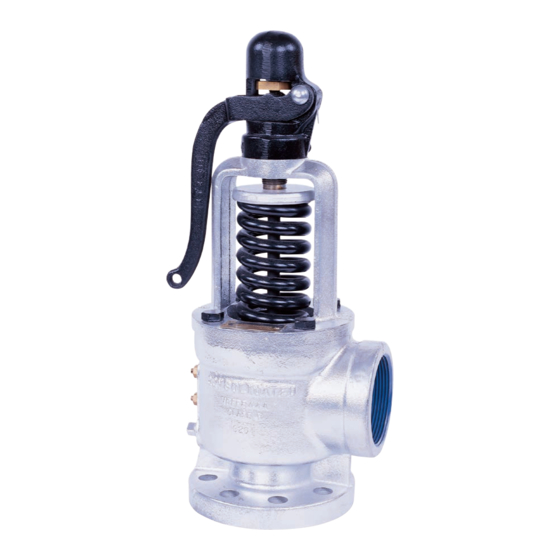
Page 11: Consolidated Safety Valve Type 1511
Drop Lever Pin Floating Washer Lift Stop Figure 2: Spindle Locknut Cap and Lifting Lever Assembly 1. Not Shown. Required for 5-26 psi (0.34-1.79 bar). | 11 © 2020 Baker Hughes Company. All rights reserved. Consolidated 1511 Series Safety Valve Instruction Manual... -
Page 12: Recommended Installation Practices
63.5 19.1 76.2 19.1 3 1/2 88.9 19.1 101.6 19.1 76.2 19.1 3 1/2 88.9 19.1 101.6 19.1 4 1/2 114.3 19.1 101.6 19.1 101.6 19.1 152.4 19.1 12 | © 2020 Baker Hughes Company. All rights reserved. Baker Hughes... -
Page 13: Outdoor Safety Valve Installation
| 13 © 2020 Baker Hughes Company. All rights reserved. Consolidated 1511 Series Safety Valve Instruction Manual... -
Page 14: Disassembly Of 1511 Series Safety Valve
Setting, Testing and Resealing the Valve 4. Two (2) ring laps per valve size and type Occasionally, remachining the seat bushing may be 1. See maintenance Tools and Supplies in Section XVI. 14 | © 2020 Baker Hughes Company. All rights reserved. Baker Hughes... -
Page 15: Machining
1000 grit Kwik-Ak-Shun Grinding Compound lap from running off the seating surface, as this may d. Lint free wipers for cleaning cause the seat to become scratched or uneven. | 15 © 2020 Baker Hughes Company. All rights reserved. Consolidated 1511 Series Safety Valve Instruction Manual... -
Page 16: Reconditioning A Ring Lap
The ring lap is ready to use on the next valve. A lap that is flat within one light band is considered satisfactory for use. Information on the monochromatic light and optical flat is available upon request from the Baker Hughes Field Service Department. Figure 6: Spindle Check Stand Table 2: Spindle Critical Dimensions C max. -
Page 17: Spindle Runout
The 1511 Safety Valve is designed with a Flat Solid Disc (FSD) in either a low (LP) (HP) pressure (LP) or high pressure (HP) version (Refer to Table 4). | 17 © 2020 Baker Hughes Company. All rights reserved. Consolidated 1511 Series Safety Valve Instruction Manual... - Page 18 5.795 ± .005 147.19 ± 0.13 4.682 ± .003 118.92 ± 0.08 .149 ± .002 3.78 ± 0.05 Figure 8: LP Flat Solid Disc All Orifices - 124 psig & below 1. All other dimensions identical to values found in Tables 5a & 5b 18 | © 2020 Baker Hughes Company. All rights reserved. Baker Hughes...
- Page 19 G min Orifice .937 23.80 .937 23.80 1.187 30.15 1.375 34.93 1.375 34.93 1.500 38.10 1.750 44.45 2.187 55.55 Figure 9: Bushing Seat | 19 © 2020 Baker Hughes Company. All rights reserved. Consolidated 1511 Series Safety Valve Instruction Manual...
-
Page 20: Reassembly
Care must be taken to tighten the factory field service department for suggestions on the yoke down evenly to prevent distortion and special coating or plating procedures which will protect the misalignment. parts. 20 | © 2020 Baker Hughes Company. All rights reserved. Baker Hughes... -
Page 21: Setting And Testing
Now the valve is ready to test. Continue repeating this procedure until the valve opens at, or below, the set pressure recorded on the nameplate. | 21 © 2020 Baker Hughes Company. All rights reserved. Consolidated 1511 Series Safety Valve Instruction Manual... - Page 22 STAMP ±3 percent of set pressure ASME Section VIII Note: Baker Hughes recommends that the maximum operating pressure never exceeds 94 percent of the set pressure of the 1511 series safety valve. 22 | © 2020 Baker Hughes Company. All rights reserved.
-
Page 23: Hydrostatic Testing & Gagging
Boiler pressure should be increased to 80 percent of the pressure of the low set valve before applying the gags. Hand tighten the gags of drum and superheater valves with only a light force. | 23 © 2020 Baker Hughes Company. All rights reserved. Consolidated 1511 Series Safety Valve Instruction Manual... -
Page 24: Application Of Test Gags (All Pressures)
The upper ring may be positioned by turning the upper adjusting ring down towards the nozzle bushing, until it becomes level with the bottom of disk. Then after choosing 24 | © 2020 Baker Hughes Company. All rights reserved. Baker Hughes... -
Page 25: Electronic Valve Testing (Evt)
XIV. Setting and Testing (Cont’d) Adjusting Ring Settings Note: It is important to note that all adjustments of adjusting rings are Baker Hughes initial adjustments only, and are not intended to be final adjustments. This final adjustment must be made on the operating system with conditions approximating those that will be realized under actual operating conditions. -
Page 26: Trouble Shooting The 1511 Series Safety Valve
Excessive inlet piping pressure drop Reduce inlet pressure drop to less than one-half of required valve blowdown by redesigning inlet piping. Valve size improper for application Verify valve sizing 26 | © 2020 Baker Hughes Company. All rights reserved. Baker Hughes... -
Page 27: Maintenance Tools And Supplies
Brand Application Points Size Container Part No. All threaded connections 2 oz. VA437 Nickel Ease Spindle Tip-Ball End Spindle-Washer Bearing Radius Compression Screw-Bearing | 27 © 2020 Baker Hughes Company. All rights reserved. Consolidated 1511 Series Safety Valve Instruction Manual... -
Page 28: Replacement Parts Planning
CLASS II 85 percent CRITICAL CLASS III SELDOM REPLACED 95 percent CLASS IV HARDWARE 99 percent PRACTICALLY NEVER CLASS V 100 percent REPLACED Consult the Recommended Spare Parts list (see Section XIX) to define the parts to be included in the inventory plan. Select parts and specify quantities. 28 | © 2020 Baker Hughes Company. All rights reserved. Baker Hughes... -
Page 29: Identification And Ordering Essentials
Baker Hughes guarantees the parts • The Consolidated valve products have been in use since 1879 • Baker Hughes offers worldwide service • Baker Hughes has fast response availability for parts | 29 © 2020 Baker Hughes Company. All rights reserved. Consolidated 1511 Series Safety Valve Instruction Manual... -
Page 30: Recommended Spare Parts
1. Refer to Figure 1 for the part numbers and their corresponding parts. Design Code Key: FSD - Flat Solid Design is designated by a “-20” in the valve code on the nameplate (example: 1 1/2” 1511H-0-2-20). 30 | © 2020 Baker Hughes Company. All rights reserved. Baker Hughes... -
Page 31: Field Service
XX. Manufacturer’s Field Service & Repair Program A. Field Service C. Maintenance Training Baker Hughes maintains one of the largest and most Rising costs of maintenance and repair in the utility competent network of field service technicians in the and process industries indicate the need for trained industry. - Page 32 Baker Hughes hereby disclaims any and all liability for any direct, indirect, consequential or special damages, claims for lost profits, or third party claims arising from the use of the information, whether a claim is asserted in contract, tort, or otherwise. Baker Hughes reserves the right to make changes in specifications and features shown herein, or discontinue the product described at any time without notice or obligation. Contact your Baker Hughes representative for the most current information. The Baker Hughes logo, Consolidated, EVT and Green Tag are trademarks of Baker Hughes Company.
Need help?
Do you have a question about the Consolidated 1511 Series and is the answer not in the manual?
Questions and answers