DITEC DAS200T Original Instructions Manual
Sliding doors automation
Hide thumbs
Also See for DAS200T:
- Quick reference (16 pages) ,
- Assembly handbook (34 pages) ,
- Technical manual (60 pages)

Related Manuals for DITEC DAS200T


Summary of Contents for DITEC DAS200T
- Page 1 Last version of this manual IP2348EN • 2022-02-10 Ditec DAS200T Technical manual DAS200TRF-DAS200TRG Sliding doors automation (Original instructions) www.ditecautomations.com...
-
Page 2: Table Of Contents
Contents General safety precautions ............................3 EC Declaration of Incorporation .............................5 Technical data ..............................6 Machinery Directive ..............................6 Standard installation ............................7 Main components ..............................8 Installing the automation ..........................9 Removing the cover ..............................9 Removal of the cover if installed side presence sensor ...................9 Removing the front casing ............................10 Rear operator installation ............................10 Front operator installation ............................11... -
Page 3: General Safety Precautions
General safety precautions ATTENTION! Important safety instructions. Please follow these instructions carefully. Failure to observe the information given in this manual may lead to severe personal injury or damage to the equipment. Keep these instructions for future reference. This manual and those for any accessories can be downloaded from www.ditecautomations.com. - Page 4 motorized door or gate • The safety devices must protect against crushing, cutting, trapping and general danger areas of the motori- zed door or gate. Display the signs required by law to identify hazar- dous areas. Each installation must bear a visible indication of the data identifying the motorized door or gate •...
-
Page 5: Ec Declaration Of Incorporation
DIN 18650-2:2010 EC type examination or certificate issued by a notified or competent body concerning the equipment: TÜV SÜD B 058029 0053 (Ditec DAS200T, Ditec DAS200TRG) TÜV SÜD B 058029 0054 (Ditec DAS200TRF) The manufacturing process ensures the compliance of the equipment with the technical file. -
Page 6: Technical Data
24 V supply Durability test 1.000.000 cycles 1.000.000 cycles TYPE OF USE Ditec DAS200T Ditec DAS200TRF Ditec DAS200TRG Sliding door automation Escape route with rubber band opening system Escape route with redundant system 1.1 Machinery Directive According to the Machinery Directive (2006/42/EC), the installer who motorises a door or gate has... -
Page 7: Standard Installation
2. Standard installation Ref. Description Automation for sliding doors Combined opening and safe closing sensor Safe opening sensor Program selector Connect the power supply cable to a type-approved omnipolar switch with category III insulation and a contact opening distance of at least 3mm. The connections to the mains and low voltage wires must be made on an independent channel sep- arated from the connections to the command and safety devices (SELV= Safety Extra Low Voltage). -
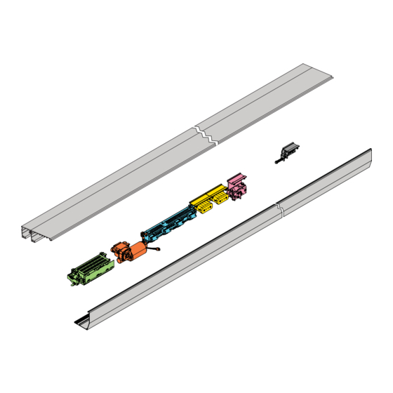
Page 8: Main Components
DAS802LOKA Anti-panic lock. Locked without power - LDP DAS802LOKB Bi-stable lock-LDB Belt transmission Mechanical stops Pulley for rubber band (DAS200TRF) NOTE: the given operating and performance features can only be guaranteed with the use of DITEC accessories and safety devices. -
Page 9: Installing The Automation
4. Installing the automation 4.1 Removing the cover 4.2 Removal of the cover if installed side presence sensor... -
Page 10: Removing The Front Casing
If the door wings are made with DITEC profiles in the ALU/PAM series: re- fer to the measurements given in the relative manuals. Drill a hole in the box using the reference line on the back and fasten it with M6 Ø12 steel plugs or 6MA... -
Page 11: Front Operator Installation
4.5 Front operator installation 1000 1000 1000 min 10 After wings installation 4.6 Installation examples using supplied wing anchoring brackets min 10 2995 max 70 max 70 KPAM45 KPAM45... -
Page 12: Installing / Removing The Cover
DAS40M8 ALU48 DAS200T-DAS40M8-ALU48 4.7 Installing / Removing the cover... - Page 13 • Secure and unsecure the open cover as shown below. CLICK...
-
Page 14: Example Of Box Fastening
5. Example of box fastening 5.1 Examples with wing connection bracket DASTAC16 min 10 DASTAC16 AC1356 DAS200T-AC1356 min 10 DASTAC16 PAM16 DAS200T-PAM16... -
Page 15: Example With Wing Connection Bracket Dast30
5.2 Example with wing connection bracket DAST30 DAST30 PAM30 DAS200T-PAM30 5.3 Example with wing connection bracket DASTAC min 10 DASTAC AC4255 DAS200T-AC4255... - Page 16 DASTAC AC4870 DAS200T-AC4870...
-
Page 17: Preparation Of The Glass Door Wing
6. Preparation of the glass door wing The diagram indicates the process measurements of the aluminium profile AC1356 and glass. Ø10 through holes are required on the aluminium profile and Ø15 on the glass for fastening. The number of holes and related distance between centres are based on the door wing width. Silicon should ideally be used between the edge of the glass and the internal base of the profile. -
Page 18: Installing And Adjusting The Door Wings
6.1 Installing and adjusting the door wings +/- 8 +/- 19 Make sure that the central wheel [D] is adjusted as illustrated in the picture. Fix the door wing to the carriage with screws (A). The door wing can be adjusted as shown in the figure. •... - Page 19 Threaded bar= LM - 350 LM-350 LM-350 LM-383 LM-383 60 (100*) 60 (100*) DAS200TRG LM-350 LM-383 DAS200T DAS200TRF 60 (100 *) Threaded bar = LM - 350 LM-350 LM-383 60 (100*) 100 (115 DAS200TRF) Threaded bar= LM - 350...
- Page 20 Proceed as follows to adjust the overlap “S” of the door wings: Place the door in the closed position. Loosen [A] and move the door wing, increasing or decreasing the overlap “S”. Tighten A. To adjust the belt tension loosen (B) and act on register [C].
-
Page 21: Floor Guide Installation
6.2 Floor guide installation The floor guides must be made of an antifriction material such as PVC, NYLON, TEFLON. The length of the floor guide should not be greater than the overlap of between the fixed and mobile door wing and must not enter the doorway. The measurements of the code KPAM45 floor guide for telescopic door wings are indicated in the diagram. -
Page 22: Checking And Adjusting The Belt Tension
6.4 Checking and adjusting the belt tension LT ≤ 3000 = 2 mm LT > 3000 = 3 mm 6.5 Sensor positioning on the cover 6.6 External sensor cable fixing (2+2 wings operator) external sensor cable tie cable fixing... -
Page 23: Electrical Connections
7. Electrical connections Connect the automation to an efficient earthing system that complies with current safety standards. During installation, maintenance and repair operations, cut off the power supply before opening the cover to access the electrical parts. The automation protection casing must be removed by qualified personnel only. An omnipolar disconnection switch with a contact opening distance of at least 3 mm must be fitted on the mains supply. -
Page 24: Standard Electrical Connections
7.1 Standard electrical connections DAS902MP DAS902MP MCU-ER DAS200TRG DAS902BAT2 (24 V) DAS901BAT1 (12 V) DAS902BAT2: the fuse in the cable harness is T10A : Motor opening direction. See example of connection chapter 11.1.a Side presence sensor 2 Side presence sensor 1 (ref. - Page 25 Output Description Power supply unit connection Motor connection Encoder connection Connection for: - Program selector (OMS); - Network connection of interconnected operators; jumper green LED - Connector for Bluetooth interface (DAS900CTI); Green LED: If this LED is switched off or flashing, it means the control panel is malfunctioning.
-
Page 26: Control Panel Commands
Inner side opening NOTE: Power supply output for external (-) 0V accessories 24 V (+) 24V 1 A: DAS200T-DAS200TRF-DAS200TRG. Central presence sensor test The maximum absorption of corresponds Key opening to the sum of all terminals power supply Central presence sensor 2 output (1-7;... - Page 27 Contact Function Description The opening of the safety contact causes the current operation to stop. N.C. STOP WARNING: when the contact closes again, the door closes. (ref. parameter 46) WARNING: The emergency opening (battery 12 V), is priority (=door opens in case of mains power failure even if STOP contact is open). Connect side presence sensor 2 as shown in the example in SIDE (ref.
- Page 28 Connect the internal sensor as shown in the example in para- INNER SIDE 16 N.O. graph 11. OPENING The closure of the contact activates the door opening operation. POWER SUP- 24 V accessories power supply. ACCESSORIES BLOCKING Output for connecting an electro-mechanical block (optional). DEVICE The blocking device is automatically selected during the learning (ref.
-
Page 29: Das902Mp Plus Module (Optional, Mandatory On Das200Trf)
7.3 DAS902MP plus module (optional, mandatory on DAS200TRF) For extra functionality like: • close impulse; • nurse impulse; • open/closeimpulse; • emergency open impulse; • bi-stable lock; • connection of optional operation mode selector; • fire impulse; • sustainable function off; •... -
Page 30: Das902Mp Commands
7.4 DAS902MP commands max 15 error / status 42V~ / 30V (SELV) RESISTIVE LOAD ONLY Fire External alarm loop 12-24V Fire Bistable lock (auxiliary coil) (+) 24V Open USE ONLY to have Auto partial priority on the function Exit selector or in the absence of function selectors Reset (-) 0V... - Page 31 The impulse opens the door fully and stop there. BATTERY WAKE- Used for emergency opening even in the absence of mains power N.O. UP IF NO MAIN supply in conjunction with contact 1-5 with any function selector POWER setting. See contact 1-5 for connection. POWER SUPPLY TO ACCESSO- 24 V...
-
Page 32: Adjustment And Selection Of Control Functions
8. Adjustment and selection of control functions The control panel has a two-figure display that displays text and/or numbers. It has four buttons. (MMI) LEARN / EXIT SELECT LEARN / EXIT SELECT DOWN DOWN The procedure to switch on the display is as follows: press the 2-SELECT key to launch the display test NOTE: make sure all seven segments of the two displays light up correctly to avoid incorrect reading. -
Page 33: Display Test
8.1 Display test a. When the display shows " ", push the SELECT button and each of the two display win- dows make a rotating test pattern. b. Verify that all seven segments of the two display windows are lit during the test. If not there is a risk of misjudgment of the digits shown in a defective display. -
Page 34: Start Up
9. Start up NOTE: for DAS200TRF follow the start up procedure indicated in the DAS200RFKA kit manual. Before performing any type of operation, make sure that the automation is turned off and the batteries are disconnected. Start-up and adjustment must be performed in the following order when the automation is installed: 1. - Page 35 00= No access code (do not use for escape route). 01= Hold for 2s possible use with COM500ES, COM501ES, Operation mode selector key lock COM502ES (do not use for escape route). (for COM500ES, COM501ES/ER, 02= Passcode, possible use with COM500ES( do not use COM502ES/ER) for escape route), COM501ES, COM502ES.
- Page 36 During this cycle, the following accessories connected to the control panel are recognised and some parameters detected: Accessory / Parameter Parameter number High Speed Closing Presence of block and type, except bistable lock 05, 06 Whether the sensors are monitored or not 9, 16, 29, 31, 91 Presence of battery and type Power supply type...
- Page 37 If necessary, you can adjust the following main parameters:ain parameters: Parameter Description Settings High Speed Opening (cm/s) 10÷80cm/s High Speed Closing (cm/s) 10÷80cm/s Hold Open Time (00÷60s) Partial opening (00-99%) Performance adjustment. Sets how fast or slow the door shall accelerate or break. Run Program (01÷05) 01= Smooth, for light doors.
-
Page 38: Parameters
10. Parameters 10.1 Configuration parameters according to function For more information on the parameters, see paragraph 10.2 SPEED parameters Parameter Description Range High speed opening 10÷80cm/s Low speed 05÷80cm/s High speed closing 10÷80cm/s TIME parameters Parameter Description Range Hold open time 00÷60s Key hold open time 00÷60s... - Page 39 Closing max force 02÷23N x10 Power supply type.150W (01) / 75W (02) 00÷02 Door weight 00÷40kg x10 Friction 00÷99N Motor type. DAS200 (15) / DAS200T-TRF (16) / DAS200TRG (17) 15÷17 Max motor power 03÷15W x10 EMERGENCY parameters Parameter Description Range Emergency unit monitoring.
- Page 40 EMERGENCY parameters Fire impulse function terminal 18/19. Off (00) / On (01) 00÷01 (DAS902MP) Emergency open impulse function 5. Off (00) / On (01) 00÷01 (DAS902MP) Emergency button configuration 5. N.O. (00) / N.C. (01) 00÷01 (DAS902MP) LOCK parameters Parameter Description Range Lock configuration (main control).
- Page 41 OPERATION MODE SELECTOR parameters Parameter Description Range Bluetooth Power Mode. Always disabled(00), Disabled in OFF mode(01), Always 00÷02 enabled (02). Default(02) Function not available, do not modify factory setting. FUTURE USE. Operation Mode Selector Function (unit DAS902MP). Off(00) / On(01) 00÷01 Function not available, do not modify factory setting.
-
Page 42: Main Control Board Parameters
10.2 Main control board parameters In the “INSTALLATION SETTINGS” column you can note the modified setting values. Param- Factory Installation Description eter setting setting High Speed Opening (10÷80cm/s) Sets the maximum opening speed. (10= 10cm/s; 70= 80cm/s Low speed (05÷69= 05÷80cm/s; 70= automatic) The low speed is self adjusting to optimal operation if this pa- rameter is set to max. - Page 43 Sets the “winter opening” size. NOTE: A building is certified for a certain COW. Depending on how (DAS200T/TRF) many people that is allowed to be in the specific area there also has to be a certain opening width. Partial open position must be set to 80% of the certified distance in escape routes.
- Page 44 Inner Impulse (motion) Monitoring (00÷01) According to EN 16005 or DIN18650 it is a demand to have Inner AUTOMATIC impulse monitoring = On in escape routes. 00= Disables monitoring. 01= Enables monitoring. *NOTE: on DAS200TRF set to 01. NOTE: If the Configuration Tool CT is used, disable the “learn access”: (DAS200TRG) Partial Hold Open Time (00÷60s)
- Page 45 Side Presence Function (00÷01) 00= Safe Speed. If a Side Presence Impulse is activated during opening, the door shall continue to open with a safe speed (0,1 m/s). 01= Stop Door. If a Side Presence Impulse is activated during opening, the door shall stop and be stopped during the set Presence Hold Open Time (see parameter 26).
- Page 46 Sensor Type (00÷01) Select type of monitoring for the combined sensors. Choose between 1-wire (00) or 2-wire (01) monitoring. 00= 1-wire monitoring. 1-wire monitoring is used when combined sensors have only one monitoring input for both presence and impulse field. 01= 2-wire monitoring.
- Page 47 Entrematic Door Connect confirmation choice (Smartphone App) (00 ÷02) 00= No code. No code needed to set changes. (Not allowed in escape route, according to EN16005 and DIN18650). 01= Confirm Button. Need to press Confirm Button to set changes (Not allowed in escape route, according to EN16005 and DIN18650).
- Page 48 Stop Function (00÷01) When this parameter is set to On (01) the Stop impulse is enabled, otherwise it is disabled. 00= Off. 01= On. Stop Configuration (00÷01) 00 = N.O. 01 = N.C. Opening Max Force (02÷23N x 10) The force applied from the operator to the door leaf during opening. If the reopening maneuver occurs too abruptly, set parameter 49 with a value lower than the factory value (10), example 04 - 05.
- Page 49 NOTE: The weight of the door is not automatically learned on the AUTOMATIC DAS200TRF, it must be set manually. NOTE: On DAS200T/TRF set the weight of the fast wing only (2 (not on DAS200TRF) leafs in the case of a 2 + 2 automation).
- Page 50 Friction (00÷99N) The friction when moving the door is automatically measured AUTOMATIC during a Learn. NOTE: DAS200T/TRF/TRG not more than 70 N. Interlock Function (00÷01) It is necessary plus module DAS902MP 00= Off 01= On See example of connection at chapter 11.
- Page 51 Open/Close Timeout, terminal 4 - DAS902MP (00÷60 minutes) The time set in this parameter controls when a door shall start closing automatically if left open by an Open/Close impulse. 00 min= no automatic closing. Function Select terminal 2 - DAS902MP (00÷03) 00= No function.
- Page 52 ELECTRONIC OPERATION MODE SELECTOR PARAMETERS Factory Installation Parameter Description setting setting Operation mode selector variant (01÷04) 01= DO NOT USE. AUTOMATIC 02= DO NOT USE. 03= DO NOT USE. 04= ELECTRONIC SELECTOR. Operation mode selector key lock (00÷03) COM501ES/ER COM502ES/ER There are four different levels of access code choices for the operation mode selector.
- Page 53 Operator mode selector service indication (00÷01) Yellow flashing service LED. Service indication on operation mode selector. No service indication (00). Indicate service (01). See also parameters 54 and 55. 00= Off 01= On Function not available, do not modify factory setting. FUTURE USE.
-
Page 54: Example Of Connection
11. Example of connection 11.1 Combined opening and safety sensor + safety sensor on opening The electrical connections must be made when the mains power supply is switched off. PAS024ADT (1) PAS024AMR (1) PAS005AP(2) PAS024AS(W) (1) PAS005AP(1) PASAA2 (1) PAS024AS(W) (2) PASAA2 (2) With these connections, the automation opens and makes a reversal safety contact on the passage opening with a command from the internal and/or external sensor. -
Page 55: Connection To The Terminals Of The Control Unit
11.1.b Connection to the terminals of the control unit ATTENTION: if the sensor is connected to the terminals of the control unit as shown below and not to the dedicated plugs, as indicated in example 11.1.a, DO NOT cut this cable side that must be connected to the SENSOR: SENSOR Control panel... - Page 56 INNER SENSOR (sensor 1) PAS024ADT White Brown Green Yellow Pink Blue Black Grey/Pink Red/Blue SECONDARY INNER IMPULSE MONITORING INNER SENSOR (sensor 2) PAS024ADT White Brown Green Connect to MCU-9 Yellow Pink Connect to module Blue plus DAS902MP Black Connect to sensor Grey/Pink Red/Blue 1 Pink...
-
Page 57: Interconnection Of Operators
11.2 Interconnection of operators 11.2.1 Interconnection cable Interconnection cable is used for controlling several operators with one operation mode selectors (OMS) and for synchronization. Operators can communicate with each other by connecting an interconnection cable between the operators. Cable connection: Pin1 to Pin 1... -
Page 58: Parameter Configuration For Interconnection
11.2.3 Parameter configuration for interconnection NOTE: Do not connect the operation mode selector (OMS) before the configuration of 6C is done on all MCUs. One of the operators has to be the main MCU (MCU-1). The main MCU shall have the value 01 in parameter 6C. -
Page 59: Synchronization
11.4 Synchronization Synchronization is when two operators work together. The doors opens and closes at the same time. A typical use is when two big single sliders are put together to get one big clear opening width. Synchronized can only be done between two operators, not more. For synchronization: set parameter 6b= 01 on all MCUs;... - Page 60 The electrical connections must be made when the mains power sullpy is switched off. Set the following parameters in all MCUs: • 6A= 01 Interlock function; • 90= 03 Interlock out; • 91= 04 Interlock in. After adjustment press the LEARN button for 2 seconds, the display flashes See parameter 25 for Interlock disable time Do not use interconnection cable, for con-...
-
Page 61: Entrematic Door Connect App
12. ENTREMATIC DOOR CONNECT App If the operator is equipped with an OMS BLE, ( type COM501ES, COM501ER, COM502ES, COM502ER) it is possible to change the mode selections withthe smartphone appENTREMATIC DOOR CONNECT. COM501ES/ER COM502ES/ER Installation of the app • Download the app ENTREMATIC DOOR CONNECT, at App Store or Google Play. -
Page 62: Installation
13.3 Installation Two-way system In a two-way system Entry and Exit is done through one door. Parameter settings Set the three parameters Flow (3D), Flow Exit Only (3E) and Flow Restriction (3F) functions Use the following parameter setting if the door shall remain closed when the Flow Limit is reached: Parameter name MCU-1 Flow... -
Page 63: Sensors
13.4 Sensors The impulse sensors that shall be used have to be uni-directional (meaning that the outer/inner impulse is only activated when approaching the door). : It is important to set Presence 1 sensitivity as high as possible, without triggering when no person is activating the sensor (ghosting). -
Page 64: Troubleshooting
14. Troubleshooting Problem Solution Check and change the functions selector switch settings. The automation doesn't open and the Make sure there are no objects on the sensor's detection path. motor doesn't start up Check the power supply switch inside the building. Check any locks, releasing them if necessary. -
Page 65: Activ Error Indication
The door leaf may also be jamming on the floor or on the weather proofing brush strips. Clean the floor guide, adjust the door leaf height/depth or take other necessary measures e.g. replacement of worn parts until the door leaf is running smoothly when manually operated. - Page 66 The control unit does not get a test an- Check that the monitoring output is connect- swer from the activation unit. ed to terminal 6, or that the sensor is con- nected to the correct plug & play connector, Side Side Presence 1 Presence 2...
- Page 67 Ambient temperature measurement RESET, and if the problem remains, replace is wrong. the main control unit. Ambient Temperature Error Not possible to activate brake chopper. RESET, and if the problem remains, replace Brake Chopper Error the main control unit. The internal A/D converter is broken. RESET, and if the problem remains, replace the electronic unit having a flashing or ex- A/D Converter Error...
- Page 68 Check that the operator is a Ditec operator. CTI Brand Mismatch Error (CTI) or the MCU is not of the Ditec. It is not possible to replace an Ditec operator component with a component from a different brand. Main error: E7 Motor Temperature High...
- Page 69 Main error: E8 Non-critical Error Detailed error Reason Remedy The main control unit cannot write RESET, and if the problem remains, replace EEPROM Non-critical error log or event log information the main control unit if it is important to read to the EEPROM memory.
-
Page 70: Routine Maintenance Plan
15. Routine maintenance plan Perform the following operations and checks every 6 months, according to the intensity of use of the automation. With power supply and batteries disconnected: Clean the mobile parts (the wheels, the carriage slide guides and the floor guides). Check the belt, the rubber band (DAS200TRF) and its tension.
Need help?
Do you have a question about the DAS200T and is the answer not in the manual?
Questions and answers