Advertisement
Advertisement
Table of Contents

Subscribe to Our Youtube Channel
Related Manuals for Migatronic Automig X


Summary of Contents for Migatronic Automig X
- Page 1 INSTRUCTION MANUAL AUTOMIG X Valid from 8647 50170005...
-
Page 3: Table Of Contents
TECHNICAL DATA........................12 WELDING SCHEDULES......................13 Only first-class materials have been used for the development and production of MIGATRONIC welding machines. The materials are subject to current control and quality supervison and then processed and mounted together into MIGATRONIC welding machines. -
Page 4: General Description
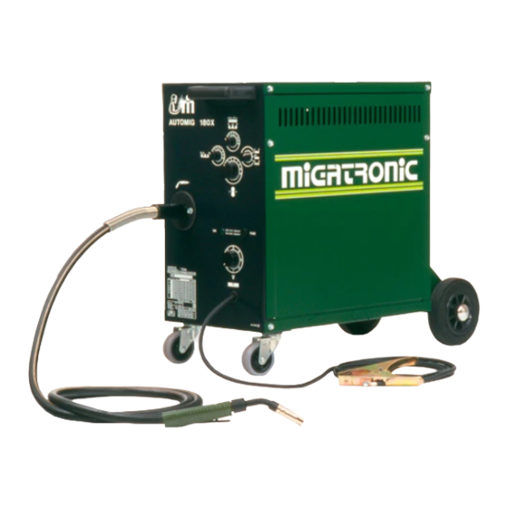
GENERAL DESCRIPTION MIGATRONIC welding machines, type Automig: 140 Mono X, 140 X, 180 Mono X, 180 X, 185 X, 200 X, 250 X and 300 X have been developed for thin plate welding and car body repair. The Automig 140 Mono X and 180 Mono X are designed to normal single-phase 220-240 V plug (F+0+earth)/10 Amp(16Amp) where as the Automig 140 X, 180 X, 185 X, 200 X, 250 X, 300 X are designed for three-phase 220-380 V (3F+earth)/10Amp. -
Page 5: Initial Operating
INITIAL OPERATING Mains connection: Input voltage should be as stated on the type plate of the machine. If dual voltage, the tapping must be checked before mains connection. Shielding gas connection: The shielding gas bottle is mounted on the machine and the regulator on the bottle. If the regulator is equipped with flowmeter, the gas quantity is adjusted on 5-15 litres/min. -
Page 6: Control Switches/Instruction
CONTROL SWITCHES/INSTRUCTIONS 1. Welding time: With this switch the welding time is chosen, when 2 is in position: interval and spot. 2. Switch: Seam: The switch is set at seam. The trigger on the welding handle is activated, welding starts. By letting go the trigger you stop the welding process. -
Page 7: Welding Technique
WELDING TECHNIQUE Setting of the machine The setting of a MIG-MAG welding machine demands some practice from the welder, the machine having two control points that have to conform. These two are the wire feed speed and the welding voltage. The welding current is determined by the wire feed speed, and it should correspond to the workpiece. -
Page 8: Maintenance
MAINTENANCE The following items demand special attention: Wire feed unit This unit is to be checked regularly at the wire feed roller and the wire nozzles, as it is of great importance for a satisfactory welding result and a minimum of wear and tear that the wire passes through the mechanism without any deformations of the wire or the wire feed roller. -
Page 9: Faults
FAULTS FAULT: PROBABLE CAUSE: Too little welding effect 1. One of the three fuses in the main switch is not The welding seam forms a bead. working (one phase is missing). 2. The welding voltage is too low. Switch one setting higher. The wire feed is blocking. -
Page 10: Replacement Of Control Unit
REPLACEMENT OF CONTROL UNIT Switch off current. Remove buttons on the front plate. Remove side panel. Disconnect multiplug outlets and unscrew the nuts. Dismount potentiometer for pause time. Pull out control unit. Mount the new control unit inversely. Do not connect the machine before the multiplug is in the right place. Plug... -
Page 11: Replacement Of Wire Guide Liner
REPLACEMENT OF WIRE GUIDE LINER Unscrew the Allen screw, disconnect the gas hose and the control wire, pull out the welding hose. Dismount the welding torch. Unscrew the Allen screw for fixing the wire guide liner. The nozzle to which the wire guide liner has been fixed can now be pulled out to the rear. -
Page 12: Technical Data
TECHNICAL DATA 140 MX 180 MX 185 X 140 X 180 X 200 X 250 X 300 X Mains voltage 50 Hz 1x220V 1x220V 1x380V 3x380V 3x380V 3x380V 3x380V 3x380V Mains voltage 50 Hz 1x240V 1x240V 1x415V 3x415V 3x415V 3x415V 3x415V 3x415V Mains voltage 50 Hz... -
Page 13: Welding Schedules
TABLES FOR SETTING OF THE MACHINE These tables are only intended as a guide, as the datas may change depending on the length of the arc, the torch handling and the position of the welding seam. Furthermore, the values change if the mains voltage is appreciably above or beneath 380V (220V). The values are based on CO shielding gas.
Need help?
Do you have a question about the Automig X and is the answer not in the manual?
Questions and answers