
Subscribe to Our Youtube Channel
Related Manuals for Regulus RGMAT E G60


Summary of Contents for Regulus RGMAT E G60
- Page 1 Installation and Operation Manual RegulusRGMAT E G60 LOAD UNIT with UPM 3, insulated for heating systems RGMAT E G60...
- Page 2 This Load Unit is intended for hydronic fireplaces and solid-fuel boilers. 2. RGMAT E G60 Description RGMAT E G60 keeps the temperature at the boiler inlet above the flue gas condensation temperatures, which prevents so called low-temperature corrosion of the boiler combustion chamber. This limits con- densation and boiler tarring significantly, the efficiency of fuel combustion increases and service life of the boiler is extended.
- Page 3 3. RGMAT E G60 Connection Diagram Possible Connection Example I. The diagram shows a typical connection of a solid-fuel boiler, thermal store and a heating circuit (with a recommended CSE MIX W pump station - not included in supply). If the boiler is also used for DHW heating, it is recommended to install also CSE OTS ZV W pump station (not included in supply).
- Page 4 4. Function description of a TSV3B valve TSV3B TSV5B 6/4Mx5/4F load valve is fitted with an integrated thermostatic insert that will close the A inlet (from a heating system), if the return water temperature to the boiler (AB outlet) is lower than the opening one. As soon as the opening temperature is reached, the thermostat starts opening the A inlet slowly and mixing the cold return water with the hot water from the boiler...
-
Page 5: Pump Control
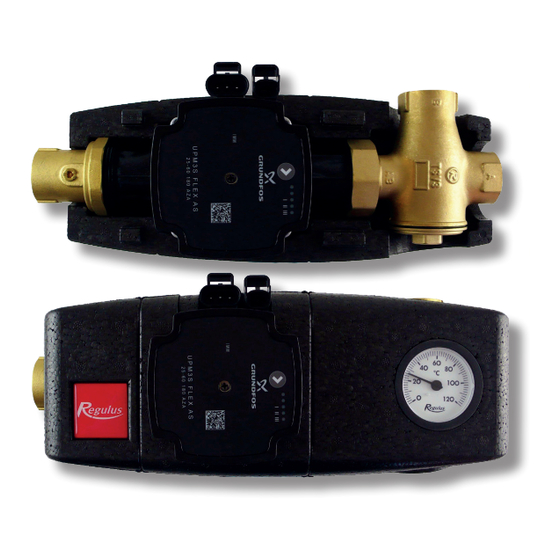
5. UPM3 FLEX AS 25-60 180 Pump Design Wet-running circulation pump with G 6/4” M connection. Electrical Data Power supply 230 V, 50 Hz Power consumption (min./max.) 2/42 W Current (min./max) 0.04/0.40 A IP rating IP44 Max. speed 5288 rpm Weighted average power ≤... -
Page 6: Control Mode
Performance display DISPLAY - LED MARKING The LED marking is further omitted for better clarity. DISPLAY PERFORMANCE CURVE Max. H STATE (upper graph) LOW PERFORMANCE MEDIUM PERFORMANCE HIGH PERFORMANCE WARNING: LEDs may be mirrored, depending on the specific pump type. GREEN LED FLASHING FREQUENCY PWM SIGNAL RECEPTION 1 flash per second... - Page 7 Permissible positions Pump wiring N (brown) L (brown) PE (yellow-green) PWM GDN (blue) PWM out (black) PWM in (brown) power supply (A) socket for power supply (A) and signal (B) connectors and signal transmission (B)
-
Page 8: Installation Options
Load Unit needs to be turned by 180° and the TSV3B valve turned as shown in the pics below. FLOW DIRECTION SMĚR PROUDĚNÍ FLOW DIRECTION SMĚR PROUDĚNÍ FLOW DIRECTION SMĚR PROUDĚNÍ v1.0-04/2022 ©2022 We reserve the right to errors, changes and improvements without prior notice. REGULUS spol. s r.o. E-mail: sales@regulus.eu Web: www.regulus.eu...
Need help?
Do you have a question about the RGMAT E G60 and is the answer not in the manual?
Questions and answers