
Subscribe to Our Youtube Channel
Related Manuals for Regulus BIO 55 MIX-BP G75 1F


Summary of Contents for Regulus BIO 55 MIX-BP G75 1F
- Page 1 Installation and Operation Manual BIO 55 MIX-BP G75 1F LOAD UNIT BIO 55 MIX-BP G75 1F...
-
Page 2: Table Of Contents
C.3.5. Necessary Accessories for Variant 4..........16 C.3.6. Optional Accessories for Variant 1, 2 and 4 ......... 16 D. Servicing, Maintenance ..................17 D.1. Boiler and Heating Circuit Pumps .............. 17 D.2. Ball Valves ....................17 Regulus BIO 55 MIX-BP G75 1F - www.regulus.eu │... -
Page 3: Safety Instructions
● Any interventions in the electrical installation must be carried out by a person qualified according to the applicable standards and regulations. ● The BIO 55 MIX-BP G75 1F load unit is in no way a replacement for the safety components of the heating system, hot water system and boiler. These safety elements must always be installed in accordance with the applicable standards and regulations. -
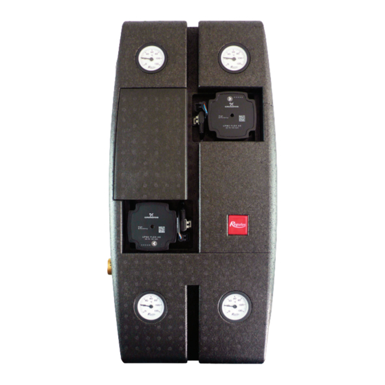
Page 4: Load Unit Components
* The G 1/2“ F free outlets from ball valves on pos. 7 and 18 can be used for connecting further accessories. If you do not need to connect any, the outlet remains plugged. Regulus BIO 55 MIX-BP G75 1F - www.regulus.eu │... -
Page 5: Load Unit Data
Load Unit power supply (powered from an external controller) Load Unit max. power input 120 W IP rating of the Load Unit IP20 Table of Kvs values Mixing valve 6.3 m Ball valves 20.2 m Regulus BIO 55 MIX-BP G75 1F - www.regulus.eu │... -
Page 6: Pressure Drop Graph
B.3. PRESSURE DROP GRAPH BOILER SIDE HEATING CIRCUIT PERFORMANCE CURVES FOR UPM3 FLEX AS 25-75 130 PUMP Curve (upper graph) (lower graph) Regulus BIO 55 MIX-BP G75 1F - www.regulus.eu │... -
Page 7: Dimensions
B.4. DIMENSIONS Note: The dimensional diagram of the open load unit is rotated for illustrative purposes, the outlets for the thermal store connection are mutually aligned (see side view). Regulus BIO 55 MIX-BP G75 1F - www.regulus.eu │... -
Page 8: Load Unit Installation
Loosen the nuts at both the Move the pump to the side to allow free access discharge and suction ports of the pump to the elbow. so that you can easily handle the pump. Regulus BIO 55 MIX-BP G75 1F - www.regulus.eu │... - Page 9 Replace all the remaining pieces of insulation tighten both nuts and return back the to their original places. pump insulation piece. The load unit should now look like this. Reinstall the top part of the insulation. Regulus BIO 55 MIX-BP G75 1F - www.regulus.eu │...
-
Page 10: Hydraulic Connection Of The Load Unit
Mixing valve G 1/2“ F Ball valve w. outlet to connect optional (plugged rom the accessories* factory) * remains connected with the boiler/heating system even when the ball valve is closed Regulus BIO 55 MIX-BP G75 1F - www.regulus.eu │... -
Page 11: Pump Connection
1 flash per second 8 flashes per second When switched on, the pump runs at factory settings or the last setting. The display shows the current pump performance. Setting selection for UPM3 To select your desired setting, press the button repeatedly until you find the setting you need (see the pic. above). If you pass the desired setting, you have to go one more round until it appears again. Regulus BIO 55 MIX-BP G75 1F - www.regulus.eu │... -
Page 12: Connection Examples
PV-TOP heating system safety valve (3 bar) vessel EN-TV DHW expansion vessel EN-TOP heating system expansion vessel automatic air vent valve Magnet Filterball PV-TV DHW safety valve Regulus BIO 55 MIX-BP G75 1F - www.regulus.eu │... -
Page 13: Variant 2
PV-TOP heating system safety valve (3 bar) gauge and outlet to connect an expansion EN-TV DHW expansion vessel vessel EN-TOP heating system expansion vessel automatic air vent valve Magnet Filterball PV-TV DHW safety valve Regulus BIO 55 MIX-BP G75 1F - www.regulus.eu │... -
Page 14: Variant 3
2 boiler drain valve 3 thermal store 4 heating system expansion vessel service valve DOCHV thermal safety relief valve (e.g. BVTS) PV-TOP heating system safety valve (3 bar) EN-TOP heating system expansion vessel automatic air vent valve Magnet Filterball Regulus BIO 55 MIX-BP G75 1F - www.regulus.eu │... -
Page 15: Variant 4
EN-TV DHW expansion vessel gauge and outlet to connect an expansion EN-TOP heating system expansion vessel vessel automatic air vent valve Magnet Filterball PV-TV DHW safety valve Regulus BIO 55 MIX-BP G75 1F - www.regulus.eu │... -
Page 16: Necessary Accessories For Variant 4
– preferably the ETT M model. The temperature is set directly on the element using the control knob and thanks to its power cord with an el. plug no professional electrician is needed for wiring. Regulus BIO 55 MIX-BP G75 1F - www.regulus.eu │... -
Page 17: Servicing, Maintenance
# 21 wrench without the need to drain the system. Replaceable O-rings Regulus BIO 55 MIX-BP G75 1F - www.regulus.eu │... - Page 20 ©2022 We reserve the right to errors, changes and improvements without prior notice. REGULUS spol. s r.o. E-mail: sales@regulus.eu Web: www.regulus.eu...
Need help?
Do you have a question about the BIO 55 MIX-BP G75 1F and is the answer not in the manual?
Questions and answers