
Related Manuals for Bosch Rexroth UPE2


Summary of Contents for Bosch Rexroth UPE2
- Page 1 General operating instructions for clamping RE 51150-B/07.11 Material no. R901310980 and drive modules and drive modules with Replaces: - and without control modules English Operating instructions...
- Page 2 © This document, as well as the data, specifica- tions and other information set forth in it, are the exclusive property of Bosch Rexroth AG. It may not be reproduced or given to third parties without its consent.
-
Page 3: Table Of Contents
RE 51150-B/07.11 | Drive modules Bosch Rexroth AG 3/56 Content Content About this documentation ................5 Validity of the documentation ..............5 Necessary and amending documentation ...........5 Illustration of information ................6 1.3.1 Safety instructions ......................6 1.3.2 Symbols ..........................7 1.3.3 Abbreviations ........................7 Safety instructions ..................8 General information on this chapter ............8... - Page 4 4/56 Bosch Rexroth AG Drive modules | RE 51150-B/07.11 Operation ....................37 Maintenance and repair ................39 10.1 Maintenance documentation ..............39 10.2 Inspection, maintenance, repair ..............39 10.2.1 Filling level .........................40 10.2.2 Oil temperature (optional) ....................40 10.2.3 Filter clogging indicator (optional) ...................41 10.2.4 Pressure values........................42 10.2.5 Oil maintenance .......................42...
-
Page 5: About This Documentation
RE 51150-B/07.11 | Drive modules Bosch Rexroth AG 5/56 About this documentation About this documentation Validity of the documentation This documentation applies to the following products: • Clamping and drive module UPE2 • Drive module UPE5 This documentation is intended for assembly fitters, service technicians and plant operators. -
Page 6: Illustration Of Information
6/56 Bosch Rexroth AG Drive modules | RE 51150-B/07.11 About this documentation Illustration of information Consistent safety instructions, symbols, terms and abbreviations are used so that you can quickly and safely work with your product using this documentation. For a better understanding, they are explained in the following sections. -
Page 7: 1.3.2 Symbols
RE 51150-B/07.11 | Drive modules Bosch Rexroth AG 7/56 About this documentation 1.3.2 Symbols The following symbols indicate notes which are not safety-relevant but increase the understanding of the documentation. Table 3: Meaning of the symbols Symbol Meaning If this information is not observed, the product cannot be used and/ or operated optimally. -
Page 8: Safety Instructions
8/56 Bosch Rexroth AG Drive modules | RE 51150-B/07.11 Safety instructions Safety instructions General information on this chapter The drive module was designed and manufactured considering the provisions of directives, standards and specifications relating to this technology. However, there is still the risk of personal injury and damage to property if you do not ob- serve this chapter and the safety instructions in this documentation. -
Page 9: Improper Use
Improper use Any use deviating from the intended use is improper and thus not admissible. Bosch Rexroth AG does not assume any liability for damage caused by improper use. The user assumes all risks involved with improper use. Qualification of personnel The activities described in this documentation require basic knowledge of me- chanics, electrics and hydraulics as well as of the appropriate technical terms. -
Page 10: Product- And Technology-Related Safety Instructions
10/56 Bosch Rexroth AG Drive modules | RE 51150-B/07.11 Safety instructions Product- and technology-related safety instructions wARNING Pressurized system! Danger to life, risk of injury, severe injury when working at systems that have not been stopped! Damage to property! Ensure that the drive module is completely depressurized. -
Page 11: Safety Equipment
RE 51150-B/07.11 | Drive modules Bosch Rexroth AG 11/56 Safety instructions CAUTION Danger due to insufficient fastening! Risk of injury! Always ensure a vertical installation position (UPE2). Fasten the product using all screws according to the connection dimensions specified in the relevant data sheet. -
Page 12: Obligations Of The Operator
Drive modules | RE 51150-B/07.11 Safety instructions Obligations of the operator The operator of the Bosch Rexroth drive modules must provide personnel training on the following topics and on a regular basis: • Observation and use of the operating instructions and the legal regulations •... -
Page 13: General Warnings Of Damage To Property And Damage To The Product
RE 51150-B/07.11 | Drive modules Bosch Rexroth AG 13/56 General warnings of damage to property and damage to the product General warnings of damage to property and damage to the product NOTICE Danger due to improper handling! Damage to property! The product may only be operated according to section 2.2 "Intended use". - Page 14 14/56 Bosch Rexroth AG Drive modules | RE 51150-B/07.11 General warnings of damage to property and damage to the product NOTICE leaking or spilt hydraulic fluid! Environmental pollution and pollution of the ground water! Use an oil binding agent in order to bind the leaked hydraulic fluid.
-
Page 15: Scope Of Delivery
RE 51150-B/07.11 | Drive modules Bosch Rexroth AG 15/56 Scope of delivery Scope of delivery These operating instructions have been prepared for drive modules. In addition to the actual product itself, the scope of delivery for drive modules also includes both general and product-specific documentation. -
Page 16: Information On This Product
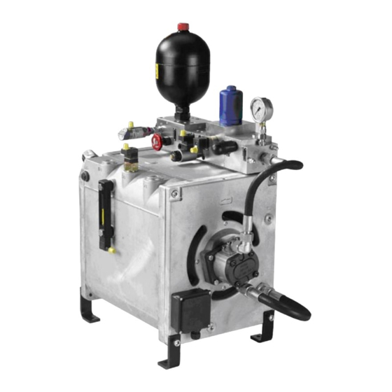
16/56 Bosch Rexroth AG Drive modules | RE 51150-B/07.11 Information on this product Information on this product Performance description A drive module constitutes a complete drive system that is delivered ready for connection. It is used for supplying hydraulic circuits with hydraulic fluid. - Page 17 RE 51150-B/07.11 | Drive modules Bosch Rexroth AG 17/56 Information on this product UPE2 Fig. 1: Drive module UPE2 Tank with electric motor and pump Control connection surface Filling plug Through holes for fastening screws Oil level display Oil drain screw...
- Page 18 18/56 Bosch Rexroth AG Drive modules | RE 51150-B/07.11 Information on this product UPE5 Fig. 2: Drive module UPE5 Tank with electric motor and pump Control connection surface Filling plug Through holes for fastening screws Oil level display Oil drain screw (not visible)
-
Page 19: Interfaces
RE 51150-B/07.11 | Drive modules Bosch Rexroth AG 19/56 Information on this product Interfaces 5.3.1 Hydraulic connections UPE2 Fig. 3: Hydraulic connections drive module UPE2 Pump connection "P" for con- Oil drain screw trol modules Tank port "T" for control modules... - Page 20 20/56 Bosch Rexroth AG Drive modules | RE 51150-B/07.11 Information on this product UPE5 Fig. 4: Hydraulic connections drive module UPE5 1 Pump connection "P" for con- 6 Tank port "T2, T3, T4, T5" trol modules 7 Suction port "S"...
-
Page 21: Electrical Connections
RE 51150-B/07.11 | Drive modules Bosch Rexroth AG 21/56 Information on this product 5.3.2 Electrical connections UPE2 Fig. 5: Electrical connections drive module UPE2 Electric motor Oil level display with level switch Temperature switch Explanation of the function: See table 8. - Page 22 22/56 Bosch Rexroth AG Drive modules | RE 51150-B/07.11 Information on this product UPE5 Fig. 6: Electrical connections drive module UPE5 Electric motor Oil level display with level switch Temperature switch Table 8: Electrical connections drive modules No. Element Function...
-
Page 23: Product Identification
RE 51150-B/07.11 | Drive modules Bosch Rexroth AG 23/56 Information on this product Product identification The drive module is unambiguously identified by: • Name plate • Product-specific and general documentation • Delivery note and accompanying documents UPE2 Fig. 7: Drive module UPE2... - Page 24 24/56 Bosch Rexroth AG Drive modules | RE 51150-B/07.11 Information on this product UPE5 Fig. 8: Drive module UPE5 Manufacturer Connection sizes Technical data of the electric motor Material number Date of manufacture Material short text Personal stamp of the examiner...
-
Page 25: Transport And Storage
If possible, reduce the pressure on the gas side to a value of 2 bar (200 kPa). Bosch Rexroth always delivers drive modules without hydraulic fluid. Any deviations from this rule are described explicitly in the product-specific documentation. -
Page 26: Transport By Means Of Lifting Gear And Attachment Points
26/56 Bosch Rexroth AG Drive modules | RE 51150-B/07.11 Transport and storage Carefully lift the drive module taking into consideration the stable center of gravity location and transport it to the desired position. Ensure that the control modules of the drive module do not come into contact with the attachment devices during transport. - Page 27 RE 51150-B/07.11 | Drive modules Bosch Rexroth AG 27/56 Transport and storage Tapped hole UPE5 Fig. 10: Tapped holes for ring bolt at the UPE5 (eyebolt) Transporting the drive module Screw the ring bolt (eyebolt) into the tapped hole until it is hand-tight.
-
Page 28: Freight Transport
Storage up to 3 months No special preservation necessary. Storage longer than 3 months Contact Bosch Rexroth for the preservation and later commissioning of the drive module if the drive module must be stored for a period of more than three months. -
Page 29: Assembly
RE 51150-B/07.11 | Drive modules Bosch Rexroth AG 29/56 Assembly Assembly This chapter describes the assembly of the drive module at its place of use as well as the connection of the drive module to the hydraulic system, the electrical systems and the water supply of the machine, if applicable. -
Page 30: Connecting To The Water Supply
7.5.1 Earthing and potential equalization Drive modules from Bosch Rexroth are supplied with connection for the external earthing system. Potential equalization within the drive module will only occur if the electrical wiring of the components is included in the scope of delivery. If this is not the case, potential equalization must be carried out by the machine manu- facturer when wiring the drive module to the machine. -
Page 31: Commissioning
RE 51150-B/07.11 | Drive modules Bosch Rexroth AG 31/56 Commissioning Commissioning DANGER Risk of breaking hose lines due to overload or aging! Danger to life, risk of injury! Replace the hose lines after 6 years at the latest or if damage is visible. -
Page 32: Safe Handling Of Pressure Tapping Points
32/56 Bosch Rexroth AG Drive modules | RE 51150-B/07.11 Commissioning 8.1.3 Safe handling of pressure tapping points When setting pressure valves, the respective pressures must be displayed. This can be done by using fixed installed pressure gauges, digital pressure displays or by connecting external measuring equipment. -
Page 33: Filling The Hydraulic System
RE 51150-B/07.11 | Drive modules Bosch Rexroth AG 33/56 Commissioning 8.1.5 Filling the hydraulic system CAUTION Contact with hydraulic fluid! Health hazard/impairment of health, e.g. eye injuries, skin lesions, intoxication upon inhalation! Observe the safety data sheet on the hydraulic fluid used. -
Page 34: Commissioning
34/56 Bosch Rexroth AG Drive modules | RE 51150-B/07.11 Commissioning 8.1.8 Commissioning The following steps are to be performed unless superordinate commissioning instructions applicable at machine level are to be observed. Start the electric motor in inching mode. Check the direction of rotation. -
Page 35: The Most Frequent Errors During Commissioning
RE 51150-B/07.11 | Drive modules Bosch Rexroth AG 35/56 Commissioning For more complex hydraulic systems with ring and branch lines, the flushing process must be planned in detail and undertaken with care. This is imperative if piping within the system have been welded and possibly also pickled. -
Page 36: Re-Commissioning After Extended Standstill
Bleed the hydraulic system. Observe the information in the operating instructions of the machine manufacturer. Standstill 3 months Contact Bosch Rexroth for the re-commissioning after a standstill of more than 3 months. Re-commissioning In order to re-commission the drive module, proceed as described in chapter... -
Page 37: Operation
RE 51150-B/07.11 | Drive modules Bosch Rexroth AG 37/56 Operation Operation DANGER Risk of breaking hose lines due to overload or aging! Danger to life, risk of injury! Replace the hose lines after 6 years at the latest or if damage is visible. - Page 38 Operation The drive module may only be operated if it is in an unobjectionable condition. In order to guarantee long and reliable functioning of the drive module, Bosch Rexroth recommends checking the hydraulic system and the drive module regularly: Continuously monitor noises, vibrations and temperatures.
-
Page 39: Maintenance And Repair
Replace the hose lines after 6 years at the latest or if damage is visible. Bosch Rexroth offers a wide range of repair services for maintenance of the drive module. Please send any enquiry to your nearest Bosch Rexroth service center or directly contact the headquarters. -
Page 40: Filling Level
40/56 Bosch Rexroth AG Drive modules | RE 51150-B/07.11 Maintenance and repair Before commencing the inspection, cleaning should be undertaken if necessary. Always ensure cleanliness when working at the drive module 10.2.1 Filling level Carry out a filling level control in an interval of 8 operating hours. -
Page 41: Filter Clogging Indicator (Optional)
Filter clogging indicator (optional) Check the level of contamination of the filters at intervals of 8 operating hours. Bosch Rexroth filters will be used as standard. With these filters, if the admissible differential pressure is exceeded, an optical signal is output, i.e. a red ring becomes visible. -
Page 42: Pressure Values
42/56 Bosch Rexroth AG Drive modules | RE 51150-B/07.11 Maintenance and repair 10.2.4 Pressure values The pressure values must be checked if the behavior of the drives changes (e.g. cycle time extension, end product quality, etc). Otherwise, one control at least every six months is recommended. -
Page 43: Hose Lines
RE 51150-B/07.11 | Drive modules Bosch Rexroth AG 43/56 Maintenance and repair Make sure that the maximum pressure for the accumulator is not exceeded. Ensure that the gas valve is securely closed after each inspection or adjustment. Disassembly from the system Before dismantling hydraulic accumulators, the liquid pressure in the accumulator must be reduced to ambient pressure (i.e. -
Page 44: Piping
44/56 Bosch Rexroth AG Drive modules | RE 51150-B/07.11 Maintenance and repair 10.2.8 Piping The piping consists of the pipes and the connection elements. Connection types: • Form-type fitting • Flare-type fitting • Welded conical fitting • Compression connector •... -
Page 45: External Inspection Of The Tank
RE 51150-B/07.11 | Drive modules Bosch Rexroth AG 45/56 Maintenance and repair 10.2.10 External inspection of the tank The external inspection is a visual inspection. Carry out an external inspection of the tank at least once every six months, or more frequently depending on operating conditions and use. -
Page 46: Repair
Order spare parts in writing. Please send your spare parts order to the Bosch Rexroth service next to you or directly to the headquarters (see "List of addresses" in chapter 17 "Appendix"). When ordering spare parts, please indicate the following information: –... -
Page 47: Decommissioning
RE 51150-B/07.11 | Drive modules Bosch Rexroth AG 47/56 Decommissioning Decommissioning 11.1 Preparing for decommissioning Provide a collecting tank that is large enough to accommodate the total hy- draulic fluid volume. The total volume of the hydraulic system comprises the volumes of the tank, the line system, the drives, etc. -
Page 48: Disassembly And Exchange
48/56 Bosch Rexroth AG Drive modules | RE 51150-B/07.11 Disassembly and exchange Disassembly and exchange Only disassemble the component parts as far as is necessary to undertake the required work. As a basic principle, all disassembled parts should be professionally reassembled at the intended place. -
Page 49: Disposal
RE 51150-B/07.11 | Drive modules Bosch Rexroth AG 49/56 Disposal Disposal Irresponsible disposal of the drive module may result in environmental pollution. Please therefore observe the following points: Dispose of the drive module in accordance with the currently applicable na- tional regulations in your country. -
Page 50: Extension And Conversion
Statements become invalid If you undertake any extensions to or conversions of the product marketed by Bosch Rexroth, this means you are changing the condition of the product as supplied. Any statements made by Bosch Rexroth regarding this product will then become invalid. -
Page 51: Troubleshooting
RE 51150-B/07.11 | Drive modules Bosch Rexroth AG 51/56 Troubleshooting Troubleshooting Successful troubleshooting within a drive module requires precise knowledge of the set-up and the mode of operation of the individual components. The combina- tion of hydraulic and electrical systems and electronics makes the troubleshooting even more complex. - Page 52 52/56 Bosch Rexroth AG Drive modules | RE 51150-B/07.11 Troubleshooting Table 10: Impact of defect "A": Excessive / abnormal noises Fault Possible causes Remedy Mechanical drive section Pump and/or motor fastening loose Tighten fastening Pump or motor defective Replace pump / motor...
- Page 53 RE 51150-B/07.11 | Drive modules Bosch Rexroth AG 53/56 Troubleshooting Table 13: Impact of defect "D" Oil temperature too high Fault Possible causes Remedy Pump Partial load operation of the machine, pump deliv- Check the hydraulic design after consulting with...
-
Page 54: Technical Data
54/56 Bosch Rexroth AG Drive modules | RE 51150-B/07.11 Technical data Technical data Table 15: Technical data Hydraulic fluid Mineral oil (HLP) according to DIN 51524 part 2 Please observe our specifications according to data sheet 07075 Hydraulic fluid tem- UPE2 –20 °C to 80 °C... -
Page 55: Appendix
RE 51150-B/07.11 | Drive modules Bosch Rexroth AG 55/56 Appendix Appendix 17.1 list of addresses Please refer to www.boschrexroth.com for addresses of foreign subsidiaries. - Page 56 Bosch Rexroth AG Hydraulics Zum Eisengießer 1 97816 Lohr am Main, Germany Phone +49 (0) 93 52 / 18-0 +49 (0) 93 52 / 18-23 58 documentation@boschrexroth.de www.boschrexroth.de Subject to change without notice Printed in Germany RE 51150-B/07.11...
Need help?
Do you have a question about the Rexroth UPE2 and is the answer not in the manual?
Questions and answers