Table of Contents
Advertisement
Quick Links
SIMATIC NET
PROFIBUS Optical Bus
Terminal (OBT)
Manual
C79000-G8976-C122-03
Release 2
Contents
Introduction
The SIMATIC NET PROFIBUS
OBT Product
Functional Description
Network Topology
Installation and Startup
Troubleshooting
Technical Specifications
Notes on the CE Label
References
Abbreviations
1
2
3
4
5
6
7
8
9
10
Advertisement
Table of Contents

Related Manuals for Siemens SIMATIC NET PROFIBUS OBT


Summary of Contents for Siemens SIMATIC NET PROFIBUS OBT
- Page 1 Contents Introduction SIMATIC NET The SIMATIC NET PROFIBUS OBT Product PROFIBUS Optical Bus Functional Description Terminal (OBT) Network Topology Installation and Startup Manual Troubleshooting Technical Specifications Notes on the CE Label References Abbreviations C79000-G8976-C122-03 Release 2...
- Page 2 Trademarks SIMATICR, SIMATIC HMIR and SIMATIC NETR are registered trademarks of SIEMENS AG. Third parties using for their own purposes any other names in this document which refer to trademarks might infringe upon the rights of the trademark owners.
-
Page 3: Table Of Contents
............The SIMATIC NET PROFIBUS OBT Product . - Page 4 Contents Contents PROFIBUS Optical Bus Terminal (OBT) C79000-G8976-C122-03...
-
Page 5: Introduction
Introduction The PROFIBUS OBT (Optical Bus Terminal) is a network component for use in optical PROFIBUS DP fieldbus networks. It allows the attachment of a single device without an integrated optical interface to the optical PROFIBUS DP. The following figure illustrates a typical configuration. DP node without SIMATIC S7-400 ET 200M with... - Page 6 Introduction Connections The connection between the individual nodes takes the form of an optical bus with two-fiber plastic FO cables (plastic fiber-optic cables are also known as POF, Polymer Optical Fiber) or PCF FO cables (PCF = Polymer Cladded Fiber, corresponds to HCSt fiber-optic cable).
-
Page 7: The Simatic Net Profibus Obt Product
The SIMATIC NET PROFIBUS OBT Product Supplied 1 x PROFIBUS OBT 1 x order form for the PROFIBUS OBT operating instructions Not supplied Plastic fiber -optic cable, can be purchased by the meter Tools for connectoring fiber-optic cables PROFIBUS OBT operating instructions... - Page 8 The SIMATIC NET PROFIBUS OBT Product PROFIBUS Optical Bus Terminal (OBT) C79000-G8976-C122-03...
-
Page 9: Functional Description
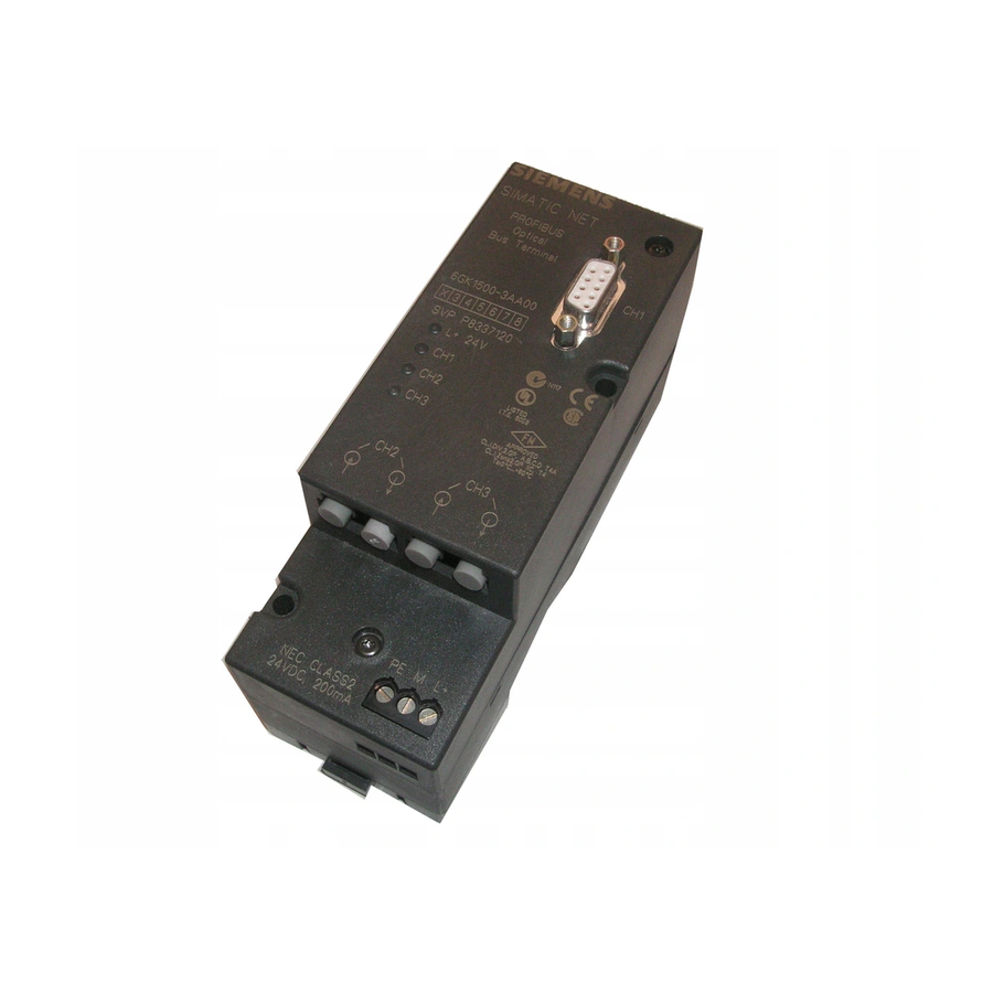
Functional Description The OBT is a repeater with 3 channels. Interfaces The OBT has the following interfaces for attachment to PROFIBUS DP segments: S Channel 1 (CH1) is an electrical RS-485 interface. This is implemented as a 9-pin D SUB female connector. A single PROFIBUS DP node can be connected via this channel or a PC, PG or OP can be connected to the OBT. -
Page 10: Automatic Transmission Rate Detection
Functional Description Automatic Transmission Rate Detection The OBT supports all PROFIBUS transmission rates (12 Mbps , 6 Mbps, 3 Mbps, 1.5 Mbps, 500 Kbps and 187.5 Kbps, 93.75 Kbps, 45.45 Kbps, 19.2 Kbps, 9.6 Kbps). The transmission rate is detected automatically. No settings are necessary. Supported FO Fiber Types The OBT supports the fiber types listed in the table below: Table 3-1... - Page 11 Functional Description L+ 24V (green) Unlit: No power supply or internal power supply is defective or short-circuited Flashes: Power supply present; Transmission rate not yet set Lit green: Transmission rate set, power supply O.K. CH1, CH2 , CH3 (channel 1 to 3, yellow) Unlit: No data being received Lit yellow:...
-
Page 12: Operator Controls
Functional Description Operator Controls The OBT itself does not have operator controls. Care must simply be taken that the PROFIBUS connecting cable (not supplied) attached to Channel 1 is terminated at both ends. PROFIBUS Optical Bus Terminal (OBT) C79000-G8976-C122-03... -
Page 13: Network Topology
Network Topology Optical Bus The OBT is operated in conjunction with other SIMATIC devices, for example the IM 153-2 FO or IM 467 FO on the optical PROFIBUS DP in the form of an optical bus. Individual PROFIBUS DP nodes with an RS-485 interface are connected to channel 1 of the OBT via a maximum 100 m long PROFIBUS cable with bus connectors fitted at both ends. -
Page 14: Using Long Fiber Optic Sections
Network Topology Using Long Fiber Optic Sections The maximum permitted length of PCF FO cables with the OBT is 300 m. If longer distances are required with fiber-optic cables, then other fiber-optic types such as graded glass fibers or monomode fibers are necessary and these can be used in a combination of OBT with OLM (Optical Link Module). -
Page 15: Attaching Rs-485 Segments
Network Topology Attaching RS-485 Segments The OBT allows the attachment of a PROFIBUS-RS 485-segment. DP node without ET 200M without SIMATIC S7-400 ET 200M without FO interface FO interface with IM 467 FO interface À À À À À À À... - Page 16 Network Topology PROFIBUS Optical Bus Terminal (OBT) C79000-G8976-C122-03...
-
Page 17: Installation And Startup
Installation and Startup Note Use the PROFIBUS OBT only as described in this manual. Note Pay particular attention to all warnings and safety-related instructions. Note The PROFIBUS OBT must only be operated with a safety extra-low voltage (SELV) complying with IEC 950/ EN 60 950/ VDE 0805 with a maximum of +32 V (typically +24 V). -
Page 18: Precedure For Installation
Installation and Startup Note The RS-485 channel CH1 of the PROFIBUS OBT is electrically isolated from the 24V input. This isolation is required for correct functioning and is not a safety measure. Note Make sure that the PROFIBUS OBT is adequately grounded by connecting the rail or mounting plate to local ground with low resistance and low inductance. -
Page 19: Installation
Installation and Startup Installation Installing the PROFIBUS OBT PROFIBUS OBT can be installed either on a 35 mm standard rail with a height of 15 mm in compliance with DIN EN 50 022 - 35 x 15 or directly on a level surface. S Select the installation location so that the climatic limit values listed in the technical specifications can be adhered to. - Page 20 Installation and Startup Installation on a Mounting Plate PROFIBUS OBTs have two holes drilled in them. This allows them to be installed on any flat surface, for example on the mounting plate of a cubicle. S Drill two holes in the mounting plate as shown in the drill template in Figure 5-2. S Secure the modules with machine screws (for example M3 x 75 and M3 x 55).
- Page 21 You can download a detailed instruction brochure with photos illustrating how to connector plastic fiber-optic cables from the Internet: S German: http://www.ad.siemens.de/csi/net S English: http://www.ad.siemens.de/csi_e/net Select SEARCH on this page and enter the number 574203 in the Entry ID box and start the search.
- Page 22 Installation and Startup Connecting the Optical Cables Figure 5-4 View of the Module from Below with the Optical Channels CH2 and CH3 A = CH2, optical receiver B = CH2, optical sender C = CH3, optical receiver D = CH3, optical sender S Connect the individual PROFIBUS OBTs using a duplex FO cable, fitted with two pairs of simplex connectors.
- Page 23 Installation and Startup Note If the fiber protrudes beyond the surface of the connector, the connector must not be inserted into the socket otherwise the optical components can be permanently damaged. Connecting the Electrical RS - 485 Cable Channel CH1 is used to connect a single PROFIBUS DP DTE. CH1 is designed as an electrical RS 485 interface with a 9-pin sub D female connector.
- Page 24 Installation and Startup PROFIBUS Optical Bus Terminal (OBT) C79000-G8976-C122-03...
-
Page 25: Troubleshooting
Troubleshooting Table 6-1 LED Display Possible Cause of Problem L+ 24V LED not lit - Power outage - OBT defective L+ 24V LED flashing - The transmission rate could not be set CH1 LED not lit - Break on one or more wires of the RS-485 LAN cable - Wires A and B of the RS-485 LAN able connected to wrong terminals - Attached PROFIBUS node is defective or not sending - PROFIBUS node not attached or attached node is not turned on... - Page 26 Troubleshooting PROFIBUS Optical Bus Terminal (OBT) C79000-G8976-C122-03...
-
Page 27: Technical Specifications
Technical Specifications Table 7-1 Technical Specifications Technical Specifications Power supply (safety extra -low voltage with reliable 24 VDC (18 V to 32 V) isolation, SELV or complying with NEC Class 2) Power consumption at 24 V input max. 200 mA Transmission rate 12 Mbps, 6 Mbps, 3 Mbps, 1.5 Mbps, 500 Kbps, 187.5 Kbps , 93.75 Kbps, 45.45 Kbps, 19.2 Kbps, 9.6 Kbps... - Page 28 Technical Specifications Wavelength 640 nm to 660 nm Permitted FO cable attenuation (with link power margin) - for plastic fiber 980/1000 13 dB - for PCF fiber 200/230 3 dB Transmission distance with 3dB link power margin - with plastic fiber 980/1000 with max.
- Page 29 Technical Specifications Relative humidity < 95% (no condensation) (IEC 68 -2 -30) Mechanical conditions Vibration during operation 10 to 58 Hz, 0.075 mm deflection 58 to 150 Hz, 10m/s (1g) acceleration (IEC 68 -2 -6) Vibration during transportation 5 to 9 Hz, 3.5 mm deflection 9 to 500 Hz, 10m/s (1g) acceleration ≤...
- Page 30 Technical Specifications PROFIBUS Optical Bus Terminal (OBT) C79000-G8976-C122-03...
-
Page 31: Notes On The Ce Label
EN 50082 -2 : 1995 Conformity Certificates The EU conformity certificates are available for the relevant authorities according to the EU directive and are kept at the following address: Siemens Aktiengesellschaft Bereich Automatisierungstechnik Industrielle Kommunikation (A&D PT2) Postfach 4848 D -90327 Nürnberg... - Page 32 Notes on the CE Label According to the directive on machines, we are obliged to point out that this product is intended solely for installation in a machine. Before the final product can be put into operation, it must be tested for compliance with the directive 89/392/EEC.
-
Page 33: References
EIA Standard RS-485 (April 1983): “Standard for electrical characteristics of generators and receivers for use in balanced digital multipoint systems” SIMATIC NET Manual for PROFIBUS Networks SIEMENS AG order number: 6GK19705AC10-0BA0 SIMATIC NET Industrial Communication Catalog IK10 SIEMENS AG Bereich Automatisierungstechnik Geschäftszweig Industrielle Kommunikation SIMATIC NET... - Page 34 References PROFIBUS Optical Bus Terminal (OBT) C79000-G8976-C122-03...
-
Page 35: Abbreviations
Abbreviations Deutsche Industrie Norm (German industrial standard) Electrostatic discharge European standard Electromagnetic compatibility Fiber-optic IEEE Institute of Electrical and Electronic Engineers ISO/OSI International Standards Organization / Open System Interconnection HCSt HCSt is a registered trademark of Ensign-Bickford Optics Company and stands for “Hard Polymer Cladded Silica Fiber”. - Page 36 Abbreviations PROFIBUS Optical Bus Terminal (OBT) 10-2 C79000-G8976-C122-03...
- Page 37 Siemens AG SIMATIC NET A&D PT2 Postfach 4848 D-90327 Nürnberg From: YourName: _ _ _ _ _ _ _ _ _ _ _ _ _ _ _ _ _ _ _ _ _ _ _ _ _ _ _ _ _...
- Page 38 Your comments and recommendations will help us to improve the quality and usefulness of our publications. Please take the first available opportunity to fill out this questionnaire and return it to Siemens. Please give each of the following questions your own personal mark within the range from 1 (very good) to 5 (poor).
Need help?
Do you have a question about the SIMATIC NET PROFIBUS OBT and is the answer not in the manual?
Questions and answers