Endress+Hauser Cleanfit CUA451 Operating Instructions Manual
Retractable process assembly
Hide thumbs
Also See for Cleanfit CUA451:
- Operating instructions manual (28 pages) ,
- Operating instructions manual (28 pages)

Related Manuals for Endress+Hauser Cleanfit CUA451


Summary of Contents for Endress+Hauser Cleanfit CUA451
- Page 1 Products Solutions Services BA00369C/07/EN/14.18 71429362 2018-11-30 Operating Instructions Cleanfit CUA451 Retractable process assembly...
-
Page 3: Table Of Contents
Cleanfit CUA451 Table of contents Table of contents 11.2 Process ......40 About this document . -
Page 4: About This Document
About this document Cleanfit CUA451 About this document Warnings Structure of information Meaning This symbol alerts you to a dangerous situation. DANGER Failure to avoid the dangerous situation will result in a fatal or serious Causes (/consequences) injury. If necessary, Consequences of non-compliance (if applicable) ‣... -
Page 5: Basic Safety Instructions
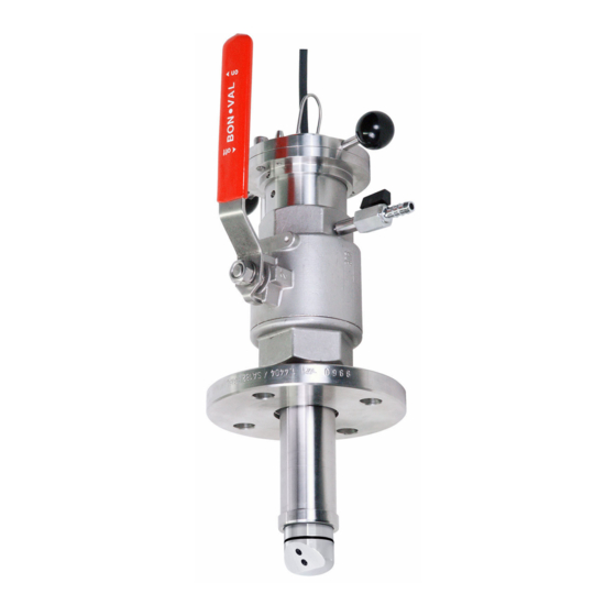
Designated use The manually operated Cleanfit CUA451 retractable assembly is designed for the installation of turbidity sensors in vessels and pipelines. Thanks to its design, it can be operated in pressurized systems. -
Page 6: Operational Safety
Basic safety instructions Cleanfit CUA451 Operational safety Before commissioning the entire measuring point: 1. Verify that all connections are correct. 2. Ensure that electrical cables and hose connections are undamaged. 3. Do not operate damaged products, and protect them against unintentional operation. -
Page 7: Product Description
Cleanfit CUA451 Product description Product description Product design A0038438 1 Assembly in operational state (ball valve open) Bracket for sensor holder Sensor holder Bayonet lock Securing screws Grease nipple Ball valve for venting or rinse connection Process connection Retraction pipe... - Page 8 Product description Cleanfit CUA451 3.1.1 Universal sensor holder The sensor holder is used to position the sensor correctly in order to ensure correct measuring accuracy. If the sensor is not positioned correctly, the ball valve may be blocked or the sensor may be located in the dead space as a result.
-
Page 9: Incoming Acceptance And Product
Cleanfit CUA451 Incoming acceptance and product identification Incoming acceptance and product identification Incoming acceptance 1. Verify that the packaging is undamaged. Notify the supplier of any damage to the packaging. Keep the damaged packaging until the issue has been resolved. -
Page 10: Scope Of Delivery
A new window (Device Viewer) opens. All of the information relating to your device is displayed in this window as well as the product documentation. 4.2.3 Manufacturer address Endress+Hauser Conducta GmbH+Co. KG Dieselstraße 24 D-70839 Gerlingen Scope of delivery The delivery comprises: •... -
Page 11: Installation
Cleanfit CUA451 Installation Installation Installation conditions 5.1.1 Dimensions Assembly with G2 thread and weld-in adapter in measuring position (long and short stroke) 270 (10.63) (3.94) 109.5 (4.31) Ø 86 (3.39) Ø 91 (3.58) (2.64) Ø 46 (1.81) 115.5 (4.55) Ø 49.3 (1.94) - Page 12 Installation Cleanfit CUA451 Assembly with G2 thread and weld-in adapter in service position (long and short stroke) (3.94) A0038630 5 Dimensions in mm (in) Dimensions depend on the sensor Endress+Hauser...
- Page 13 Cleanfit CUA451 Installation Assembly with flange connection (3.94) (3.94) Ø 46 (1.81) Ø 49.3 (1.94) A0038651 6 Dimensions in mm (in) Dimensions depend on the sensor Sensor CUS52D 26.5 (1.04) CUS50D 26.3 (1.04) CUS41/CUS51D, 14 (0.55) COS61D CUS65, COS51D 21.3 (0.84)
- Page 14 Installation Cleanfit CUA451 Sensor service position, short CUS52D 533 (20.98) CUS50D 504 (19.84) CUS41/CUS51D, 495 (19.49) COS61D CUS65, COS51D 453 (17.83) Sensor holder with sensors A0038478 7 Dimensions of sensor holder with sensors in mm (in) 5.1.2 Process connections 2"...
- Page 15 Cleanfit CUA451 Installation 5.1.3 Installation instructions Installation location The assembly is designed for installation on vessels and pipes. Suitable nozzles must be available for this. The minimum pipe diameter is DN 80. ‣ Before mounting the sensor, mount the assembly on the vessel or in the pipe.
- Page 16 Installation Cleanfit CUA451 ‣ Make sure to avoid a siphon effect at the rinse chamber outlet. The inflow to the rinse chamber is always from below. Clearance between the sensor and pipe wall If the sensor is installed in pipes or very close to the wall, this can cause backscatter and therefore a higher sensor signal.
-
Page 17: Mounting The Assembly
Cleanfit CUA451 Installation Mounting the assembly WARNING Medium flows out. Risk of injury ‣ Only install the assembly when the process is deactivated. ‣ Before disassembling, always ensure that the process pipe and vessel are unpressurized, empty and rinsed. ‣... - Page 18 Installation Cleanfit CUA451 Releasing the screws Use the following tools to install the sensor: • 2.5 mm Allen screw • 6 mm Allen screw A0038431 Release the securing screws (item 1) and put them in a safe place within reach.
- Page 19 Cleanfit CUA451 Installation A0038433 Release the grub screw (item 1) on the underside of the bayonet nut. A0038434 Unscrew the bayonet nut and the sensor holder (item 1) from the retraction pipe. In doing so, hold the retraction pipe steady and turn the handles (2) counterclockwise (approx.
- Page 20 Installation Cleanfit CUA451 Screwing in the sensor ‣ A0038441 Screw the sensor hand-tight into the internal thread of the sensor holder. Aligning the bracket A0038442 Push the bracket out of the installation bore holes. The sensor holder bracket can be fitted in various positions at 60° intervals. In this way, you can use the bracket to mark the position of the sensor in the retraction pipe.
- Page 21 Cleanfit CUA451 Installation A0038443 11 Bracket alignment taking the example of the CUS52D sensor While paying attention to the flow side of the sensor, align the bracket with the axis of the sensor head. In this way, you can determine the position of the sensor surface in the process and align the sensor with the medium flow.
- Page 22 Installation Cleanfit CUA451 A0038433 Tighten the grub screw of the bayonet nut. 4. Connect the rinse chamber connection. Fitting the sensor in the assembly A0038445 1. Push up the hand lever as far as possible. The ball valve is open.
- Page 23 Cleanfit CUA451 Installation Disassembling the sensor holder Use the following tools to install the sensor: • 2.5 mm Allen screw • 6 mm Allen screw A0038431 Release the securing screws (item 1) and put them in a safe place within reach.
- Page 24 Installation Cleanfit CUA451 A0038433 Release the grub screw (item 1) on the underside of the bayonet nut. A0038434 Unscrew the bayonet nut and the sensor holder (item 1) from the retraction pipe. In doing so, hold the retraction pipe steady and turn the handles (2) counterclockwise (approx.
- Page 25 Cleanfit CUA451 Installation For sensors with the Memosens plug-in head ‣ Release the Memosens cable on the sensor. Changing the position of the locking ring ‣ A0038801 Move the locking ring into the correct groove that corresponds to the sensor type.
-
Page 26: Post-Installation Check
Installation Cleanfit CUA451 Post-installation check • After mounting, check all the connections to ensure they are secure and leak-tight. • Ensure that the hoses of the (optional) rinse water connections cannot be removed without force. These pipes are in open contact with the medium and must be secured accordingly. -
Page 27: Commissioning
Cleanfit CUA451 Commissioning Commissioning Preparatory steps WARNING Risk of injury if medium escapes! ‣ Before commissioning, check whether rinse hoses are connected to the assembly or whether dummy plugs are fitted at the rinse connections. ‣ Otherwise, do not introduce the assembly into the process. -
Page 28: Operation
Operation Cleanfit CUA451 Operation Adapting the device to the process conditions 7.1.1 From the service position to the measuring position 1. Check the rinse chamber connections to ensure they are closed. 2. Open the ball valve. 3. Push the retraction pipe in the direction of the process as far as it will go. -
Page 29: Maintenance
Cleanfit CUA451 Maintenance Maintenance WARNING Medium flows out. Risk of injury ‣ Only install the assembly when the process is deactivated. ‣ Before disassembling, always ensure that the process pipe and vessel are unpressurized, empty and rinsed. ‣ Move the assembly to the service position. - Page 30 Maintenance Cleanfit CUA451 • 2.5 mm Allen screw • 6 mm Allen screw A0038431 Release the securing screws (item 1) and put them in a safe place within reach. 2. Release the bayonet lock (item 2). A0038432 Taking the handles, pull out the retraction pipe (item 2) together with the sensor holder (item 1) as far as it will go.
- Page 31 Cleanfit CUA451 Maintenance A0038433 Release the grub screw (item 1) on the underside of the bayonet nut. A0038434 Unscrew the bayonet nut and the sensor holder (item 1) from the retraction pipe. In doing so, hold the retraction pipe steady and turn the handles (2) counterclockwise (approx.
- Page 32 1. Keep the sealing surfaces of the assembly free from dirt. 2. Remove caking and buildup from time to time. 3. If leaks are discovered, contact your Endress+Hauser sales office. Preparing the assembly The seals are available as an accessory kit. When replacing the seals, interrupt the process and remove the assembly completely.
- Page 33 Cleanfit CUA451 Maintenance Access to the seals A0038663 12 Seals Viton O-ring, retraction pipe Viton O-ring, between ball valve and bottom part of bayonet lock Viton O-rings, bottom part of bayonet lock Viton O-ring, sensor holder 1. Only when replacing the O-ring, item 2: unscrew the vent cock (with safety bracket).
-
Page 34: Repair
Repair Cleanfit CUA451 Repair General information CAUTION Risk of injury due to medium escaping and elevated temperatures Pressure safety is compromised ‣ Damage to the assembly, which compromises pressure safety, must be repaired only by authorized and qualified personnel. ‣... -
Page 35: Spare Parts
Cleanfit CUA451 Repair Spare parts A0038665 13 Spare parts The bayonet lock nut (item 1) and dummy plug (item 6) are not available as a spare part. The sensor holders are used to adjust the length of the different sensors to a standard installation length. -
Page 36: Return
The product must be returned if repairs or a factory calibration are required, or if the wrong product was ordered or delivered. As an ISO-certified company and also due to legal regulations, Endress+Hauser is obliged to follow certain procedures when handling any returned products that have been in contact with medium. -
Page 37: Accessories
Cleanfit CUA451 Accessories Accessories The following are the most important accessories available at the time this documentation was issued. ‣ For accessories not listed here, please contact your Service or Sales Center. 10.1 Device-specific accessories 10.1.1 Sensors Turbimax CUS50D • For nephelometric measurements of turbidity and solids in wastewater •... - Page 38 Accessories Cleanfit CUA451 M16x60 75 (2.95) 93 (3.66) Ø 165 (6.50) A0038764 14 Welding socket, dimensions in mm (in) Markings for bores, DN 50 flange Welding nipple • Welding nipple for 2" thread • Stainless steel 1.4404 (AISI 316 L) •...
-
Page 39: Service-Specific Accessories
Cleanfit CUA451 Accessories Ø 70 (2.76) Ø 165 (6.50) A0038762 16 Welding rinse socket, dimensions in mm (in) Markings for bores, DN 50 flange 10.2 Service-specific accessories Ball valve for rinse chamber • As rinse connection complementing or replacing the vent cock supplied;... -
Page 40: Technical Data
Technical data Cleanfit CUA451 Technical data 11.1 Environment Ambient temperature 0 to 50 °C (32 to 122 °F) range 11.2 Process Medium temperature 0 to 85 °C (32 to 185 °F) Medium pressure Max. 10 bar (145 psi) For manual insertion/retraction of the assembly, the medium pressure must not... - Page 41 Cleanfit CUA451 Technical data Materials Wetted: Viton (seals) Stainless steel 1.4404 (AISI 316 L) Nickel-plated brass (vent cock or rinse connection) Not wetted: Stainless steel 1.4404 (AISI 316 L) Endress+Hauser...
- Page 42 Index Cleanfit CUA451 Index Ambient temperature range ....40 Approvals ....... . . 10 Certificates .
- Page 44 *71429362* 71429362 www.addresses.endress.com...
Need help?
Do you have a question about the Cleanfit CUA451 and is the answer not in the manual?
Questions and answers