Endress+Hauser Cleanfit CPA871 Operating Instructions Manual
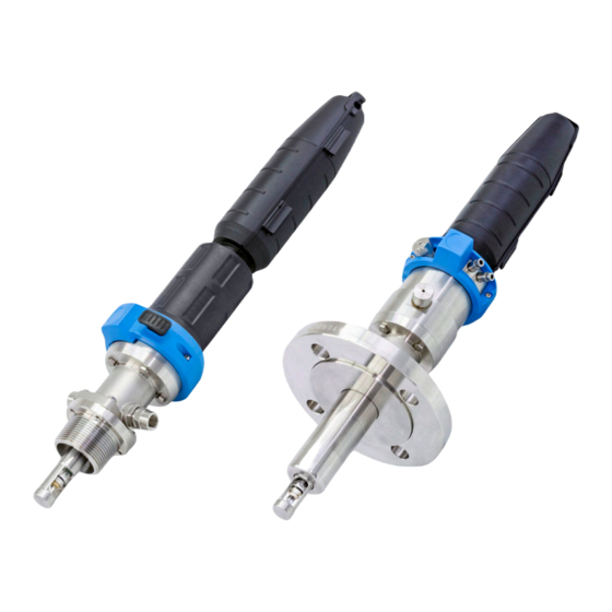
Flexible retractable process assembly for water, wastewater, chemical industry and heavy industry
Hide thumbs
Also See for Cleanfit CPA871:
- Operating instructions manual (48 pages) ,
- Operating instructions manual (92 pages)

Related Manuals for Endress+Hauser Cleanfit CPA871


Summary of Contents for Endress+Hauser Cleanfit CPA871
- Page 1 Products Solutions Services BA01323C/07/EN/05.19 71439183 2019-04-30 Operating Instructions Cleanfit CPA871 Flexible retractable process assembly for water, wastewater, chemical industry and heavy industry...
-
Page 3: Table Of Contents
Cleanfit CPA871 Table of contents Table of contents 10.3 Flow vessel ......55 About this document ....4 10.4 Sensors . -
Page 4: About This Document
About this document Cleanfit CPA871 About this document Warnings Structure of information Meaning This symbol alerts you to a dangerous situation. DANGER Failure to avoid the dangerous situation will result in a fatal or serious Causes (/consequences) injury. If necessary, Consequences of non-compliance (if applicable) ‣... -
Page 5: Basic Safety Instructions
Designated use The Cleanfit CPA871 retractable assembly, which can be manually or pneumatically operated, is designed for the installation of sensors in vessels and pipes. Thanks to its design, it can be operated in pressurized systems (→ 59). -
Page 6: Operational Safety
Basic safety instructions Cleanfit CPA871 Operational safety Before commissioning the entire measuring point: 1. Verify that all connections are correct. 2. Ensure that electrical cables and hose connections are undamaged. 3. Do not operate damaged products, and protect them against unintentional operation. -
Page 7: Product Description
Cleanfit CPA871 Product description Product description Product design Rinse connection (outlet) Automatic limit position lock, process Connection for limit position switch Automatic limit position lock, service Fastening ring for protective cover Pneumatic connection (move to measuring position) Pneumatic connection (move... - Page 8 Product description Cleanfit CPA871 3.1.1 Operating principle A0039361 2 Sealing system, assembly in service position Rinse chamber, inlet Seal, drive (1 x O-ring) Leakage hole Rinse chamber, outlet Seal, rinse chamber (1 x O-ring) Process seal (2 x O-ring) Rinse chamber The assembly is open to the process during insertion/retraction;...
-
Page 9: Incoming Acceptance And Product
Cleanfit CPA871 Incoming acceptance and product identification Incoming acceptance and product identification Incoming acceptance 1. Verify that the packaging is undamaged. Notify the supplier of any damage to the packaging. Keep the damaged packaging until the issue has been resolved. -
Page 10: Product Identification
Incoming acceptance and product identification Cleanfit CPA871 Product identification 4.3.1 Nameplate The nameplate provides you with the following information on your device: • Manufacturer identification • Order code • Extended order code • Serial number • Ambient and process conditions •... -
Page 11: Certificates And Approvals
Cleanfit CPA871 Incoming acceptance and product identification Certificates and approvals The design of the assembly was reviewed and registered by the Canadian safety authorities for all Canadian provinces in accordance with the requirements of the "Canadian Registration Number (CRN)" system. -
Page 12: Installation
Installation Cleanfit CPA871 Installation Installation conditions 5.1.1 Orientation The assembly is designed for installation on tanks and pipes. Suitable process connections must be available for this. NOTICE Frost damage to the assembly ‣ If used outdoors, ensure that water cannot penetrate the drive. - Page 13 Cleanfit CPA871 Installation 5.1.2 Dimensions Short version (2.40) (2.40) (4.61) (2.40) (4.21) 42 (1.65) (0.47) (0.47) A0023897 A0023894 5 Manual drive, short version, dimensions in 4 Pneumatic drive, short version, dimensions in mm (in) mm (in) Assembly in measuring position...
- Page 14 Installation Cleanfit CPA871 Long version (2.40) (2.40) (4.21) (2.40) (4.21) 42 (1.65) (0.7) (0.7) (0.47) (0.47) A0023898 A0023895 7 Manual drive, long version, dimensions in 6 Pneumatic drive, long version, dimensions in mm (in) mm (in) Assembly in measuring position...
- Page 15 Cleanfit CPA871 Installation Immersion chamber version (2.40) (2.40) (4.61) (2.40) (4.21) 42 (1.65) (1.5) (1.5) (0.47) (0.47) A0023896 A0023899 8 Immersion chamber version with pneumatic drive, 9 Immersion chamber version with manual dimensions in mm (in) drive, dimensions in mm (in)
- Page 16 Installation Cleanfit CPA871 Process connection height Process connection Height XP in mm (in) CB Clamp 2" 16 (0.63) ISO2852, ASME BPE-2012 A0024100 CC Clamp 2½" 16 (0.63) ISO2852, ASME BPE-2012 A0024101 FA Flange DN 40 PN16, EN1092-1 18 (0.71) A0024102 FB Flange DN 50 PN16, EN1092-1 18 (0.71)
- Page 17 Cleanfit CPA871 Installation 5.1.3 Immersion depths A0023893 10 Immersion depths in mm (in) Short stroke, 36 mm (1.42 in) Long stroke, 78 mm (3.07 in) Immersion version Versions Process connection CB Clamp ISO2852 14.9 (0.59) 61.0 (2.40) 119.9 (4.72) 171.9 (6,76)
-
Page 18: Mounting The Assembly
Installation Cleanfit CPA871 A0039342 11 Immersion depth in mm (in) for process connection NA thread ISO 228 G1¼ Mounting the assembly 5.2.1 Installation Measuring system A0029620 12 Measuring system (example) Cleanfit assembly CPA871 Measuring cable Liquiline CM44x transmitter... - Page 19 Cleanfit CPA871 Installation A0039105 13 Sealing system using a bypass Check valve Valve open/closed, sealing water function Wastewater Shutoff valve open/closed Water/cleaning agent The seals must be checked and serviced regularly. Therefore measures must be taken to separate the assembly from the process, e.g., by installing a bypass.
- Page 20 Installation Cleanfit CPA871 Installing/removing the assembly from the process WARNING Risk of injury from high pressure, high temperature or chemical hazards if process medium escapes. ‣ Wear protective gloves, protective goggles and protective clothing. ‣ Mount the assembly only if vessels or pipes are empty and unpressurized.
- Page 21 Cleanfit CPA871 Installation Pneumatic connection for automatic operation Prerequisites: • Air pressure 4 to 7 bar (absolute pressure) (58 to 102 psi) • Compressed air quality in accordance with ISO 8573-1:2001 Quality class 3.3.3 or 3.4.3 • Solids class 3 (max. 5 μm, max. 5 mg/m , contamination with particles) •...
- Page 22 Installation Cleanfit CPA871 A0039091 A0039092 16 4/2-way valve 17 5/2-way valve Connection 1 is attached to the compressed air supply. Connections 2 and 4 are used to attach to the pneumatic drive. Connection 3 and, if present, connection 5 are not attached; they are used to vent the drive.
- Page 23 Cleanfit CPA871 Installation Rinse connections The service chamber connections make it possible to rinse the chamber (including the sensor) with water or cleaning solution. The pressure difference between the sealing water and process must not exceed 6 bar (87 psi).
- Page 24 Installation Cleanfit CPA871 Connecting the limit position switches With limit position detection, you can notify a system located downstream (transmitter, switching amplifier, output interface terminal) whether the assembly is in the measuring or service position (in the case of manual drive, only the measuring position is queried).
- Page 25 Cleanfit CPA871 Installation A0022163 20 Connecting cable for limit position switch on transmitter, switching amplifier, output interface terminal etc. Measuring position Measuring position Service position Service position Only pins 1 and 2 are assigned for manually activated assemblies with one switch (measuring position).
-
Page 26: Installing The Sensor
Installation Cleanfit CPA871 Installing the sensor 5.3.1 Preparing the sensor and assembly A0030154 22 Installing the sensor Thrust collar with O-ring 1. Remove protection cap from sensor. Ensure that O-ring and thrust collar (→ 22, pos. 1) are present. - Page 27 Cleanfit CPA871 Installation A0030155 23 Sensor installation options Sensor adapter Retraction pipe Sensor adapter is on top of the retraction pipe Sensor adapter is below the retraction pipe (not visible) Depending on the assembly version, the sensor adapter is either visible (, pos. A) or installed inside the retraction pipe where it is not visible (pos.
- Page 28 Installation Cleanfit CPA871 Installing and removing sensors if the sensor adapter is visible (A) A0030156 24 Installing the sensor Open-ended wrench (AF 17/19 mm) Protective cover Dummy plug Sensor Gel and KCl sensors can be installed in this version.
- Page 29 Cleanfit CPA871 Installation Installing and removing sensors if the sensor adapter is not visible (pos. B) A0030157 25 Installing the sensor Socket wrench (AF 17/19 mm) Protective cover Dummy plug (protection cap) Sensor Retraction pipe Gel sensors can be installed in this version. To install KCl sensors, you will need a "Gel - KCl adapter".
- Page 30 Installation Cleanfit CPA871 7. Mount the protective cover on the assembly. When doing so, guide the measuring cable through the cable run (top of protective cover). Always install the protective cover before moving the assembly to measuring position. The protective cover cannot be removed in measuring position. This prevents the sensor from being removed.
-
Page 31: Post-Installation Check
Cleanfit CPA871 Installation 5. Screw in the "Gel - KCl adapter" (pos. 6) in place of the dummy plug and hand-tighten (3 Nm (2.2 lbf ft)). 6. Hand-tighten the lock nut in a clockwise direction, and then use an open-ended wrench (AF 24 mm) to tighten it by ¼... -
Page 32: Commissioning
Commissioning Cleanfit CPA871 Commissioning Before commissioning, ensure that: • all seals are correctly seated (on the assembly and on the process connection). • the sensor is correctly installed and connected. • the water connection at the rinse connections is correct (if present) or the rinse connections are sealed. -
Page 33: Operation
Cleanfit CPA871 Operation Operation Adapting the assembly to the process conditions A0023307 28 Position markings (service position) Assembly with pneumatic drive The assembly with pneumatic drive does not have any operating elements. Assembly with manual drive Manual drive Unlocking button (measuring position) - Page 34 Operation Cleanfit CPA871 7.1.1 Manual operation A0030330 30 Direction of rotation Unlocking button (service position) Unlocking button (measuring position) Moving the assembly from the service position to the measuring position 1. Press the unlocking button (A). 2. With the unlocking button (A) pressed during the first quarter turn, rotate the drive in a clockwise direction so that the sensor holder moves into the process (only possible with the sensor installed).
- Page 35 Cleanfit CPA871 Operation Inserting/retracting the assembly if the compressed air supply fails A0030306 31 Failure of compressed air supply Limit position lock for service position Limit position lock for measuring position CAUTION Risk of injury due to high medium pressure ‣...
-
Page 36: Maintenance
Maintenance Cleanfit CPA871 Maintenance WARNING Risk of injury if medium escapes ‣ Before each maintenance task, ensure that the process pipe is empty and rinsed. ‣ Move the assembly to service position. ‣ The assembly may contain residual medium; please rinse thoroughly before commencing work. - Page 37 Cleanfit CPA871 Maintenance Interval Maintenance measures ‣ Biannually Clean the assembly thoroughly. ‣ or after 5000 strokes (whichever comes Remove the residual medium. ‣ first) Replace all seals in contact with the medium. Check mobility of retraction protection. Remove the sensor.
-
Page 38: Cleaning The Assembly
Maintenance Cleanfit CPA871 Cleaning the assembly WARNING Risk of injury if medium escapes ‣ Before each maintenance task, ensure that the process pipe is empty and rinsed. ‣ Move the assembly to service position. ‣ The assembly may contain residual medium; please rinse thoroughly before commencing work. -
Page 39: Cleaning Agent
Cleanfit CPA871 Maintenance Cleaning agent WARNING Organic solvents containing halogens Limited evidence of carcinogenicity! Dangerous for the environment with long-term effects! ‣ Do not use organic solvents that contain halogens. WARNING Thiocarbamide Harmful if swallowed! Limited evidence of carcinogenicity! Possible risk of harm to the unborn child! Dangerous for the environment with long-term effects! ‣... -
Page 40: Replacing Seals
Maintenance Cleanfit CPA871 Replacing seals To replace the seals in the assembly, you must interrupt the process and remove the assembly completely. CAUTION Risk of injury due to residual medium and elevated temperatures ‣ When handling parts that are in contact with the medium, protect against residual medium and elevated temperatures. - Page 41 Cleanfit CPA871 Maintenance 8.5.1 Standard version Seal replacement in the process connection A0030290 32 Replacing seals, Part 1 Securing screws AF8 1. Release the four securing screws (pos. 1). A0030291 33 Replacing seals, Part 2 Process connection O-ring in process connection 2.
- Page 42 Maintenance Cleanfit CPA871 Seal replacement in the rinse connection A0030292 34 Replacing seals, Part 3 Lock nut Rinse connection adapter 1. Release the lock nuts (pos. 4) using an open-ended wrench or socket wrench (AF 19 mm, in protective cover).
- Page 43 Cleanfit CPA871 Maintenance Seal replacement in the support housing A0030310 36 Replacing seals, Part 4 Securing screws AF8 1. Release the four securing screws (pos. 1). Service chamber Support housing O-ring, support housing O-rings, bottom of service chamber O-rings, rinse connection adapter...
- Page 44 Maintenance Cleanfit CPA871 Assembly Fit support housing and service chamber together A0030343 38 Assembling the support housing Service chamber Support housing Positioning pin Positioning groove 1. Place the support housing (pos. 7) on a level surface. The positioning groove (pos. 14) is visible from above.
- Page 45 Cleanfit CPA871 Maintenance 2. Apply pneumatic pressure to the rinse chamber inlet (max. 6 bar absolute pressure). 3. Hold the assembly under water as far as the rinse chamber. In so doing, do not submerge the drive in the water.
- Page 46 Maintenance Cleanfit CPA871 8.5.2 Immersion chamber version Seal replacement in the process connection A0030294 40 Replacing seals, Part 1 1. Release the four securing screws (pos. 1). A0030295 41 Replacing seals, Part 2 Process connection O-ring in process connection 2.
- Page 47 Cleanfit CPA871 Maintenance Seal replacement in the rinse connection adapter A0030292 42 Replacing seals, Part 3 Lock nut AF19 Rinse connection adapter AF17 1. Release the lock nuts (pos. 4) using a 19 mm open-ended wrench or socket wrench (in protective cover).
- Page 48 Maintenance Cleanfit CPA871 Seal replacement in the immersion chamber Support housing Immersion chamber - top part Immersion chamber - middle part Immersion chamber - bottom part Securing screws, 2.5 mm (0.1 in) Allen screw O-ring, outer service chamber O-ring, top of service chamber...
- Page 49 Cleanfit CPA871 Maintenance Assembly In the immersion chamber version, the inlet and outlet of the service chamber are fixed. When assembling the immersion tube, please ensure that the leakage hole (pos.11), the service chamber outlet (pos. 12) and the immersion chamber (pos. 16) are all in one line.
- Page 50 Maintenance Cleanfit CPA871 A0030347 46 Assembling the support housing and immersion chamber Support housing Positioning pin Positioning groove 4. Place the support housing (pos. 7) on a level surface. The positioning groove (pos. 14) is visible from above.
- Page 51 Cleanfit CPA871 Maintenance 12. Hold the assembly under water as far as the rinse chamber. In so doing, do not submerge the drive in the water. The test is successful if no air bubbles appear. Endress+Hauser...
-
Page 52: Repair
The product must be returned if repairs or a factory calibration are required, or if the wrong product was ordered or delivered. As an ISO-certified company and also due to legal regulations, Endress+Hauser is obliged to follow certain procedures when handling any returned products that have been in contact with medium. -
Page 53: Accessories
Cleanfit CPA871 Accessories Accessories The following are the most important accessories available at the time this documentation was issued. ‣ For accessories not listed here, please contact your Service or Sales Center. The following accessories can be ordered via the product structure (see ordering information): •... -
Page 54: Installation Material For Rinse Connections
Accessories Cleanfit CPA871 10.1 Installation material for rinse connections Filter set CPC310, CVC400 • Water filter (dirt trap) 100 µm, complete, incl. angle bracket • Order No. 71031661 Pressure reducer kit • Complete, incl. manometer and angle bracket • Order No. 51505755 Hose connection set G¼, DN 12... -
Page 55: Flow Vessel
Cleanfit CPA871 Accessories 10.3 Flow vessel Flow vessel • Flange DN 25 ISO 1092-2 PN16 • Material: stainless steel 1.4404 (AISI 316 L) 25 (0.98) 66 (2.6) 160 (6.3) A0039147 49 Dimensions in mm (in) Dummy plug available for maintenance purposes... -
Page 56: Sensors
Accessories Cleanfit CPA871 10.4 Sensors 10.4.1 pH sensors Orbisint CPS11D / CPS11 • pH sensor for process technology • Optional SIL version for connecting to SIL transmitter • With dirt-repellent PTFE diaphragm • Product Configurator on the product page: www.endress.com/cps11d www.endress.com/cps11... - Page 57 Cleanfit CPA871 Accessories Ceragel CPS72D / CPS72 • ORP electrode with reference system including ion trap • Product Configurator on the product page: www.endress.com/cps72d www.endress.com/cps72 Technical Information TI00374C 10.4.3 pH ISFET sensors Tophit CPS441D / CPS441 • Sterilizable ISFET sensor for low-conductivity media •...
-
Page 58: Absorption Sensor
Accessories Cleanfit CPA871 10.4.5 Conductivity sensors Memosens CLS82D • Four-electrode sensor • With Memosens technology • Product Configurator on the product page: www.endress.com/cls82d Technical Information TI01188C 10.4.6 Oxygen sensors Oxymax COS22D / COS22 • Sterilizable sensor for dissolved oxygen • With Memosens technology or as an analog sensor •... -
Page 59: Technical Data
Cleanfit CPA871 Technical data Technical data 11.1 Environment Ambient temperature -10 to +70 °C (+10 to +160 °F) Storage temperature -10 to +70 °C (+10 to +160 °F) 11.2 Process Process temperature -10 to +140 °C (14 to 284 °F) for all materials except PVDF and conductive PVDF -10 to +100 / 90 °C (14 to 212 / 194 °F) for PVDF and conductive PVDF materials... - Page 60 Technical data Cleanfit CPA871 Pressure temperature Manual drive, assembly insertion/retraction up to 8 bar ratings p [psi] p [bar] T[°C] T[°F] A0039156 50 Pressure temperature ratings for basic and immersion chamber version for materials 1.4404, Alloy C22 and PEEK...
- Page 61 Cleanfit CPA871 Technical data p [psi] p [bar] T[°C] T[°F] A0039268 52 Pressure temperature ratings for basic and immersion chamber version for materials 1.4404, Alloy C22 and PEEK (CPA871-++G/H++++++ ) Basic and immersion chamber version Static range, assembly insertion/retraction not permitted...
- Page 62 Technical data Cleanfit CPA871 Pneumatic drive, assembly insertion/retraction up to 16 bar p [psi] p [bar] T[°C] T[°F] A0039157 54 Pressure temperature ratings for basic and immersion chamber version for materials 1.4404, Alloy C22 and PEEK (CPA871-++E/F++++++) Basic and immersion chamber version...
-
Page 63: Mechanical Construction
Cleanfit CPA871 Technical data 11.3 Mechanical construction Design, dimensions → Section "Installation" Rinse chamber volume Volume cm³ (in³)(max.) Volume cm³ (in³)(min.) Single chamber 12.02 (0.73) 2.81 (0.17) Immersion chamber, short 15.75 (0.96) 6.73 (0.41) Immersion chamber, long 17.14 (1.05) 8.12 (0.5) -
Page 64: Index
Index Cleanfit CPA871 Index Accessories ....... . 53 Safety instructions ......5 Approvals . - Page 68 *71439183* 71439183 www.addresses.endress.com...
Need help?
Do you have a question about the Cleanfit CPA871 and is the answer not in the manual?
Questions and answers