Table of Contents
Advertisement
Quick Links
novoSchwank
Radiant Tube Heater
20S L / 25S L / 35S L / 45S L / 55S L
single heater and flue gas collection system [herringbone] type F
Technical Manual
Technical Instructions
Operating Instructions
Legal Requirements
Assembly Instructions
Installation Instructions
0085BO0037
Commissioning
Service Guide
Advertisement
Table of Contents
Troubleshooting

Subscribe to Our Youtube Channel
Related Manuals for Schwank novoSchwank 20S L


Summary of Contents for Schwank novoSchwank 20S L
- Page 1 novoSchwank Radiant Tube Heater 20S L / 25S L / 35S L / 45S L / 55S L single heater and flue gas collection system [herringbone] type F Technical Manual Technical Instructions Operating Instructions Legal Requirements Assembly Instructions Installation Instructions 0085BO0037 Commissioning Service Guide...
- Page 2 Internet: www.schwank.de Schwank companies in: Austria ▪ Belgium ▪ Canada ▪ China ▪ Czech Republic ▪ France ▪ Germany ▪ Great Britain ▪ Hungary ▪ Netherlands ▪ Poland ▪ Romania ▪ Russia ▪ Slovakia ▪ Ukraine ▪ USA ▪ Distribution in more...
-
Page 3: Table Of Contents
15 Spare parts ................................. 53 Spare parts novoSchwank 20S L – 55S L ....................53 Spare parts burner kit novoSchwank 20S L – 55S L ................54 16 EC type examination certificate ........................55 EC declaration of conformity ......................... 57... -
Page 4: Introduction
L 1 Introduction Notes for your safety Thank you for choosing a Schwank radiant tube for This appliance is designed according to the your heating-system. requirements of the existing standards. Nevertheless it is possible that dangers for you and... -
Page 5: Scope Of Delivery
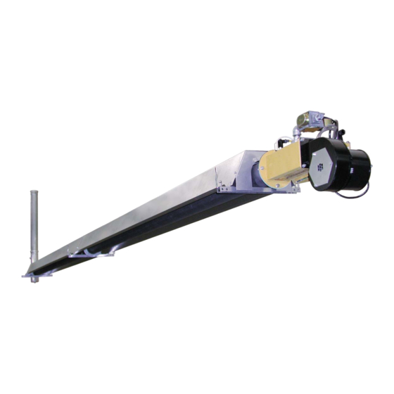
novoSchwank shape L 3 Scope of Delivery Reflector end plate Tube bar Reflector Tubes Burner kit Flange packing Suspension brackets Fig. 1: Tube heater novoSchwank 35S L Scope of delivery Accessories The radiant tube heater novoSchwank consists of: Central control unit SchwankControl Touch with ... - Page 6 novoSchwank shape L Structure of burner kit Fig. 2: Burner kit with burner control unit IC 4000/1 1. Burner control unit IC4000/1 15. Ignition cable 2. Air pressure switch 16. Ionisation cable 3. Fan air restrictor plate 17. 3-pin power supply socket [incoming side, not shown] 18.
-
Page 7: Planning
novoSchwank shape L 4 Planning Distances to flammable materials in the radiant area Room temperature control Radiant tubes must be positioned so that the surface temperature of: Radiant tube heating-systems must be equipped with a temperature control. components with flammable materials, Section heating is allowed without temperature ... -
Page 8: Positioning
Avoid therefore inflexible suspension. Do not use fixing elements like open hooks etc. SCHWANK GmbH will not accept liability Hang the heater in balance. We recommend the for damages caused by incorrect use of turnbuckles or adjustable steel cable grips mounting of the burner kit. -
Page 9: Air Supply / Exhaust Requirements
For exact dimensioning and positioning of supply air and exhaust air outlet of the building according to EN 13410 or G 638-2 please contact Schwank GmbH, phone +49 [0] 221 / 7176 0. - Page 10 3. Exhaust flue with individual exhaust system - construction and layout of such installations must combustion air from outside the room be carried out by Schwank employees, as well as [Type C] commissioning. The strict observance of the Combustion air and exhaust air are to be...
- Page 11 novoSchwank shape L Indirect flue into the room with flue gas diverter, Type A3 For indirect flue into the room a flue gas diverter must be installed to prevent backflow of flue gas into the air inlet. Note that the flue gas diverter is mounted in a position so that the flue gas is diverted from the burner.
- Page 12 Following components are required for mounting the wall terminal stainless steel version [Distance heater- terminal approx. 1.5 m]: Stainless steel exhaust system wall terminal DN 100/160 Article no. 12202210 Fig. 9: Flexible exhaust system novoSchwank 20S L – 55S L [wall terminal], version stainless steel...
- Page 13 L Flexible exhaust system novoSchwank 20S L – 55S L [roof terminal], Type B23 - version stainless steel - Stainless flexible pipe to avoid install Please note the safety distance to with sink. flammable materials: single-wall exhaust pipe: 80 mm...
- Page 14 Tube heater novoSchwank must only be done by Schwank. Spiral duct and connection elements for Planning details have to be strictly exhaust collecting system [different adhered to during mounting and dimensions] assembly.
-
Page 15: Legal Requirements
novoSchwank shape L 5 Legal Requirements In Germany the following rules, standards and We recommend that these installation guidelines regulations must be observed. should be observed with the relevant Building Standards Regulations of your country. Comply EnEV Verordnung über with any local by-laws and the current IEE Wiring energiesparenden Wärmeschutz Regulations. -
Page 16: Operation
Servicing should be carried out not less than once a year by a qualified service engineer. After any servicing, the heater SCHWANK will not accept liability damages must be recommissioned as detailed in caused by improper assembly and/ or operating Chapter 12. -
Page 17: Technical Specification
20S L / 25S L [all dimensions in mm] Detail B Detail A see page 18 see page 18 novoSchwank 35S L [all dimensions in mm] Fig. 12: Dimensions novoSchwank 20S L / 25S L / 35S L [view from below]... - Page 18 novoSchwank shape L novoSchwank 45S L [all dimensions in mm] novoSchwank 55S L [all dimensions in mm] Fig. 13: Dimensions novoSchwank 45S L / 55S L [view from below] Detail A Detail B Tube overhang to last suspension Cross dimensions burner unit bracket 45mm for 20S L –...
-
Page 19: Technical Data
novoSchwank shape L Technical data novoSchwank 20S L 25S L 35S L 45S L 55S L Natural gas H Gas input - gross [kW] 16,7 21,1 32,2 43,3 54,4 Gas input - net [kW] 15.0 19.0 29.0 39.0 49.0 Gas consumption [m G 20 1.50 1.91... -
Page 20: Operating Description
novoSchwank shape L 8 Operating description Fault Start-up If no flame is reported during the pre-purge If heat demand exists, the fan will start up period [including 1 repetition of ignition process], automatically. A differential pressure arises in the the burner control unit IC 4000/1 will switch off the burner box, which is reported to the ignition kit via radiant tube, error will give, fan runs in post-purge the differential pressure switch. -
Page 21: Assembly Instructions
Reflectors will be fixed on both front plates by 3x M 5 screws and self-locking nuts. Mounting of the burner kit with valve on the top. Black clamping bar!! Flue gas diverter Fig. 14: Mounting novoSchwank 20S L / 25S L [all dimensions in mm]... - Page 22 novoSchwank shape L Assembly Supporting sleeve 4 rivets (stainless) Ø 4.8 mm novoSchwank 35S L hole size Ø 4.9 mm Tools you need • hexagonal wrench [width: 10, 13] • hexagonal spinner [width: 7 and 8] hand rivet tool, drill machine, ...
- Page 23 novoSchwank shape L Supporting sleeve Assembly 4 rivets (stainless) Ø 4.8 mm novoSchwank 45S U hole size Ø 4.9 mm Tools you need • hexagonal wrench [width: 10, 13] • hexagonal spinner [width: 7 and 8] hand rivet tool, drill machine, ...
- Page 24 novoSchwank shape L Supporting sleeve Assembly 4 rivets (stainless) Ø 4.8 mm novoSchwank 55S L hole size Ø 4.9mm Tools you need • hexagonal wrench [width: 10, 13] • hexagonal spinner [width: 7 and 8] hand rivet tool, drill machine, ...
-
Page 25: Assembly Burner Kit Exhaust Gas Collection System
novoSchwank shape L Assembly burner kit exhaust gas collection system Conversion kit burner kit single heater to exhaust gas collection system Article No. 126999 9 Conversion kit includes the components for converting the burner kit for use in an exhaust gas Fig. - Page 26 novoSchwank shape L Fig. 22: View burner kit after conversion Fig. 23: Assembly connection parts exhaust gas...
-
Page 27: Installation Instructions
10 Installation Please consider the pressure drop of the upstream instructions mounted gas connection and gas filter. For the detailed pressure drop value of the Schwank gas- pipe-systems see Tab. 7. Danger of fire and explosion! Unprofessional handling of gas pipes,... - Page 28 novoSchwank shape L Note the following points while installing the gas-pipe-system: Use only gas lines as per national standards. Never hang heaters on the gas pipes. Mount a manual gas cock upstream of every radiant tube. Close all gas cocks before carrying out the leak test and disconnect the connection between the gas cock and the burner to avoid damages to the gas regulator and gas...
-
Page 29: Exhaust Flue Installation Single Heater
When starting the central exhaust fan for the first time all tube connections have to be checked for tightness. If the Schwank planning requires a condensate run off, this part must be mounted directly in front of the exhaust fan [deepest point of the system]. -
Page 30: Electrical Installation [Wiring Diagram]
novoSchwank shape L Electrical installation [wiring diagram] Danger of electric shock! Electric shocks are highly dangerous! Working at the electrical equipment of the appliance is only allowed by professional personnel observing the current IEE regulations. Isolate the electrical supply while working at the electrical equipment of the appliance and safeguard the appliance against unintentional... -
Page 31: Electrical Connection Operation With Modbus Control
novoSchwank shape L Electrical connection Electrical connection exhaust gas collecting system Operation with MODBUS control [herringbone system] After conversion of the heaters to operation with Route a flexible 3-wire electrical connection exhaust gas collection system they can be cable [max. 3 x1.5 mm ] for power supply burner electrically connected as described above. - Page 32 novoSchwank shape L Fig. 30: Wiring scheme burner kit novoSchwank with MODBUS control to SchwankControl Touch...
- Page 33 novoSchwank shape L Fig. 31: Wiring scheme burner kit novoSchwank via relay control SchwankControl Touch - without MODBUS control...
- Page 34 novoSchwank shape L Fig. 32: Wiring scheme burner kit novoSchwank exhaust gas collecting system with SchwankControl Touch / extension kit Fan Control SAV1...
- Page 35 novoSchwank shape L Fig. 33: Wiring scheme burner kit novoSchwank 1-stage with alternative control kit SRT-1 Fig. 34: Wiring diagram burner kit novoSchwank...
-
Page 36: Commissioning Instructions
novoSchwank shape L Commissioning instructions Before commissioning A qualified service engineer must carry out this operation. The correct operation and fixing of the heater is prerequisite for the warranty. Checking gas lines and flue system is not included in this service. -
Page 37: Parameter Ic 4000/1 And Setting
Parameter IC 4000/1 and setting The burner control unit IC 4000/1 is already factory preset. The parameters can be read out by the Schwank Service Software IC 4000 [RS-485 interface board] and if necessary to be changed. Parameter selection and settings can made manually direct at IC 4000/1 by the two push buttons SW 2 and SW 3 and the 7-segment display. -
Page 38: Assignment Modbus Address
novoSchwank shape L Fig 35: 7-segment display and push buttons IC 4000/1 ON normal working mode DISP1 is blank. When you need to enter parameter setting: - Press SW2 and SW3 buttons together for 3 seconds. - Parameter number “1” is displayed on DISP1. - Press SW2 to increase the parameter number, press SW3 to decrease the parameter number. -
Page 39: Adjusting Nominal Thermal Load At Single-Stage Operation
novoSchwank shape L Adjusting nominal thermal load at single-stage operation Attention! The burner kit is pre-adjusted on natural gas / propane. Do not put the appliance into operation uncontrolled. Adjusting the nozzle pressure 1. Open first the gas cock which is at the end of the flexible gas hose [Fig. - Page 40 novoSchwank shape L Fig. 39: Board IC4000/1 with 7-segment display and push buttons SW 2 / SW 3...
-
Page 41: Commissioning Exhaust Gas Collecting System [Herringbone]
For first start up and commissioning of the system please request a Schwank service engineer to Required negative pressure level at test nipple attend Adjustment by Schwank is a condition of nozzle pressure [cold conditions]: our warranty. - novoSchwank 20S L…55S L: -0.8…-1.5 hPa... -
Page 42: Determination Of Nozzle Pressure
novoSchwank shape L Determination of nozzle pressure Example for the determination of the nozzle pressure Diagram 2: Wobbe-Index profile Natural gas novoSchwank... -
Page 43: Service Guide / Trouble Shooting
novoSchwank shape L 12 Service guide / Trouble shooting Maintenance and annual check A regular maintenance is the requirement for a Any deviations must be fixed immediately. Defect faultless operation of the appliance. parts must be changed directly. According to the National Standard Regulations, Maintenance work on gas valves, flame sensing heating-systems with radiant tubes must be and safety devices can only be maintained by the... -
Page 44: Error Codes
novoSchwank shape L Error codes Error in gas valve Gas valve drive or feedback feedback error If an error occurs, all gas valves are closed and the check circuitry lockout message output [230V] is activated and Ionization Ionization signal is the error code is stored internally and transmitted component error out of range... -
Page 45: Troubleshooting / Error Causes
novoSchwank shape L Troubleshooting / Error causes Error code 1: - no gas [e.g. gas line not vented, gas cock closed] - faulty gas valve - Ignition and ionization electrodes damaged / dirty - wrong setting gas throttling screw - poor grounding Error code 2: - poor low ionization current [<0,7 A DC] - too low connection pressure... -
Page 46: Change Of Gas Family
novoSchwank shape L 13 Change of gas family Fig. 40: Change of gas family Burner baffle [only 20S L / 25S L / 35S L] Burner cup Burner nozzle Air baffle plate [only 20S L / 25S L / 35S L / 45S L / 55S L] ... -
Page 47: Accessories
novoSchwank shape L 14 Accessories Ball guards Ball protection grids acc.18032-3 for using heaters in sport halls [grid 40x40 mm]. Delivery scope Mounting set complete for each type of heater existing of: novoSchwank shape L 20S L 25S L 35S L 45S L 55S L Ball protection grid L=1443mm... - Page 48 novoSchwank shape L 7. Put next segment ball protection grid L= 1843 mm from below on angled brackets and mount clamps with self-locking nuts M8 Last segment ball protection grid L= 1843 mm protects the burner unit at the bottom. 8.
- Page 49 novoSchwank shape L Fig. 46: Loose mounted clamp Fig. 43: Fixed end bracket on last suspension bracket Fig. 47: Fixing front protection cover burner on protection grid burner top Fig. 44: Fixed angled bracket on suspension bracket Fig. 45: Holding bracket novoSchwank L...
-
Page 50: Reflector Elongation
novoSchwank shape L Reflector elongation Vertical elongation of reflectors b=415 mm for thermal protection. The numbers of reflector elongation [single sheets] is depending on required protection [one side both side, protection length] and the power of the radiant heater. Delivery scope The required reflector elongation can be compiled depending on the extent of necessary protection out of the following basic elements:... -
Page 51: Set Angled Mounting Tubes
novoSchwank shape L Set angled mounting tubes Gas filter groups Bracket to ensure form and position of reflectors To avoid technical problems with the gas when the heater is mounted angled [>15°]. combination valves which are caused by Mount bracket to at each junction point pollution of dust or rust coming out of the gas pipe reflector/reflector, not at reflector end caps. -
Page 52: Water Protection Cover Burner Kit
novoSchwank shape L Water protection cover burner kit Article number: 02671201 Protection cover of the burner kit 20S U – 55S U with protection class IP 55 against water or aggressive mediums, cover complete in stainless steel. In delivery scope a mounting set existing of: ... -
Page 53: Spare Parts
Tube clamp 126 4529 5 Tube clamp [black painted] 126 4510 4 Mounting set novoSchwank 20S L / 25S L [not in Fig. 56] 126 7105 0 Mounting set novoSchwank 35S L [not in Fig. 56] 126 7106 0 Mounting set novoSchwank 45S L [not in Fig. 56] 126 7107 0 Mounting set novoSchwank 55S L [not in Fig. -
Page 54: Spare Parts Burner Kit Novoschwank 20S L - 55S L
Spare part HONEYWELL for HONEYWELL 1-stage / modulating VK 4105N 5016 192 0761 3 Burner cup steel complete novoSchwank 20S L – 45S L, Natural gas + Propane / 55 S L Propane 126 7219 0 Burner cup steel complete novoSchwank 55S L Natural gas 126 7468 0 Fan complete with venturi novoSchwank 20S L –... -
Page 55: Ec Type Examination Certificate
novoSchwank shape L 16 EC type examination certificate... - Page 56 novoSchwank shape L...
-
Page 57: Ec Declaration Of Conformity
novoSchwank shape L 17 EC declaration of conformity...
Need help?
Do you have a question about the novoSchwank 20S L and is the answer not in the manual?
Questions and answers