
Related Manuals for Maxon SD-125E


Summary of Contents for Maxon SD-125E
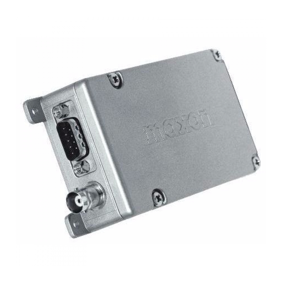
- Page 1 All manuals and user guides at all-guides.com SD-125E SERVICE MANUAL MaxonCIC Corp. Chongho Bldg, #7-61, Yangjae-Dong, Seocho-Ku, Seoul, 137-130, Korea Phone: (82) 2 3498 - 3114; Fax: (82) 2 3498 -3113 October 2008...
-
Page 2: Table Of Contents
All manuals and user guides at all-guides.com MAXONCIC SD-125E RF LINK MODULE 1. TABLE OF CONTENTS 2. SPECIFICATIONS 3. UNPACKING 4. INTRODUCTION 5. FEATURES 6. THEORY OF OPERATION 6.1 INTRODUCTION 6.2 DIGITAL CIRCUITS 6.3 RF CIRCUITS 6.4 RF CIRCUITS PLL SYNTHESIZER 6.5 RECEIVER... - Page 3 All manuals and user guides at all-guides.com MAXONCIC SD-125E RF LINK MODULE 17.9 DIGITAL BOARD(148-174MHz)SCHEMATIC 17.10 RF BOARD VHF PRINTED CIRCUIT BOARDS 17.11 RF BOARD UHF PRINTED CIRCUIT BOARDS 17.12 DIGITAL BOARD PRINTED CIRCUIT BOARDS 18. EXPLODED VIEW & PARTS LIST...
-
Page 4: Specifications
All manuals and user guides at all-guides.com MAXONCIC SD-125E RF LINK MODULE GENERAL Equipment Type ……………………………………………………… Data radio Performance Specifications………………………………………… TIA/EIA -603 / IC, RSS212 Band …………………………………………………………………… VHF(SD-125VEV2) / UHF(SD-125VEU) Channel Spacings …………………………………………………… 25 kHz, 12.5 kHz programmable RF Output Power ……………………………………………………... - Page 5 All manuals and user guides at all-guides.com MAXONCIC SD-125E RF LINK MODULE TRANSMITTER Specification Carrier Power: ………………………………………………………… Nom. Max. Min. Hi ………………………………………………………………………5W < 6W > 4.5W Low ……………………………………………………………………1W < 1.5W > 0.8W Sustained Transmission …………………………………………… Nominal conditions Time : 5 30 Sec.
- Page 6 All manuals and user guides at all-guides.com MAXONCIC SD-125E RF LINK MODULE RECEIVER Specification Sensitivity (12dB Sinad) …………………………………………… Standard B.W < -117 dBm, Narrow B.W <-118 dBm @ Nom. Condition Standard B.W < -115 dBm, Narrow B.W <-116 dBm @ Extreme Condition Amplitude Characteristic.
- Page 7 All manuals and user guides at all-guides.com MAXONCIC SD-125E RF LINK MODULE Environmental (performance without degradation unless stated) Temperature…………………………………………………………deg C Operating ……………………………………………………………-30℃ to +60℃ Degradation Specified @Extreme Storage……………………………………………………………….-40℃ to +80℃ Recharging …………………………………………………………..-10℃ to+55 ℃ ESD ………………………………………………………………….. 20kV (C-MIC≥15KV) Vibration ………………………………………………………………MIL STD 810 C Procedures Ⅰ,Ⅱ,Ⅴand IEC68 26 PROGRAMMER …………...
-
Page 8: Unpacking
All manuals and user guides at all-guides.com MAXONCIC SD-125E RF LINK MODULE The SD-125 RF Link Module is the only item included in the shipping container. - 8 -... - Page 9 1997, has adopted a safety standard for human exposure to Radio Frequency (RF) electromagnetic energy emitted by FCC requlated equipment. Maxon subscribes to the same safety standard for the use of its products. Proper operation of this radio will result in user exposure far below the Occupational Safety and Health Act (OSHA) and Federal Communications Commission limits.
- Page 10 All manuals and user guides at all-guides.com MAXONCIC SD-125E RF LINK MODULE Busy Channel Lockout 16 Channels TX Time-out Power Save 1 / 5 Watt Programmable Output 12.5 / 25 kHz Programmable Channel Spacing Busy Channel Lockout The Busy Channel Lockout feature, when enabled, disables the transmitter when the receiving channel is busy and the user attempts to transmit.
-
Page 11: Introduction
All manuals and user guides at all-guides.com MAXONCIC SD-125E RF LINK MODULE 6.1 INTRODUCTION The VHF and UHF radios are comprised of two PCB's (an RF PCB and a digital PCB). These boards are connected with an 18 pin female and male connector . The digital board is interfaced with external data equipment through the 9 pin d-sub male connector, which controls the radio and data receiving and sending . -
Page 12: Rf Circuits
All manuals and user guides at all-guides.com MAXONCIC SD-125E RF LINK MODULE 6.3 RF CIRCUITS TRANSMITTER The transmitter is comprised of: Buffer P.A. Module Low Pass Filter Antenna Switch A.P.C. Circuits BUFFER VCO output level is -6dBm and amplified to +10dBm (UHF), +6dBm (VHF). The buffer consists of Q8 and Q9 for isolation and gain. -
Page 13: Rf Circuits Pll Synthesizer
All manuals and user guides at all-guides.com MAXONCIC SD-125E RF LINK MODULE 6.4 RF CIRCUITS PLL SYNTHESIZER 12.8 MHz TCXO The TCXO contains the 3-stage thermistor network compensation and crystal oscillator and modulation ports. Compensation is ±5 PPM or less from -30c to +60c. -
Page 14: Receiver
All manuals and user guides at all-guides.com MAXONCIC SD-125E RF LINK MODULE 6.5 RECEIVER FRONT-END The receive signal is routed backward through the low pass filter, then onward to C601 of the Hybrid Receiver Front End Module to a bandpass filter consisting of (VHF C622 through C608, L607 through L604 ) and (UHF C601through C610, L601 through L603 ) is coupled to the base of Q601 which serves as an RF amplifier. - Page 15 All manuals and user guides at all-guides.com MAXONCIC SD-125E RF LINK MODULE FIRST MIXER Q16, L15 and C77 are Dual gate FET mixers which provide the 45.1 MHz intermediate frequency output. The filtered frequency from the front end module is coupled to C131 The 45.1 MHz IF output is matched to the input of the 2-pole monolithic filter by C65 and C66.
-
Page 16: Maintenance And Repair
28 in conjunction with the following procedures: • WARNING: Disconnect the SD-125E from all external equipment at the D-Sub connector prior to disassembly. 7.2 REMOVING & REPLACING THE UPPER COVER Removing the Upper Cover: Unscrew the four upper cover mounting screws located on the upper cover of the radio. -
Page 17: Removing & Replacing The Digitalboard & Shield Plate
All manuals and user guides at all-guides.com MAXONCIC SD-125E RF LINK MODULE 7.3 REMOVING & REPLACING THE DIGITAL BOARD & SHIELD PLATE Removing the Digital Board Assembly & Shield Plate: Remove the Upper Cover (refer to Removing & Replacing the Upper Cover). -
Page 18: Removing & Replacing The Rf Board
All manuals and user guides at all-guides.com MAXONCIC SD-125E RF LINK MODULE Figure 3-Shield Plate Removal 7.4 REMOVING & REPLACING THE RF BOARD Removing the RF Board Assembly: Remove the Upper Cover (refer to Removing & Replacing the Upper Cover). - Page 19 All manuals and user guides at all-guides.com MAXONCIC SD-125E RF LINK MODULE Reverse the steps taken to remove the RF Board Assembly. Figure 4-Rf Board removal - 19 -...
-
Page 20: Programming
VDC 200mA Power Supply. Refer to the ACC-900E Programming User’s Manual for detailed information on programming the SD-125E Series radio. The SD-125E UHF/VHF Receiver is by design, broad band covering UHF(400-430 MHz & 440-470 MHz &470-490 MHz) and VHF(148-174 MHz) and should require no special alignment, unless repairs are performed on the receiver portion. - Page 21 All manuals and user guides at all-guides.com MAXONCIC SD-125E RF LINK MODULE TX VCO Set the unit to the highest receive frequency 430MHz(UHF1), 470MHz(UHF2), 490MHz(UFH3), 174MHz(VHF) and verify the VCO control voltage is under 9.0 Volts. If it’s over 9.0 Volts, adjust C308 of RX VCO to 9.0 Volts...
- Page 22 Maxon’s wide range of data radio products since the crystal control module (DM-0500 series) had their squelch level setting by hardware touch up. With the SD-125E series, the squelch level to open or close (unmute or mute) is set up by software control.
-
Page 23: Test Equipment Setup
All manuals and user guides at all-guides.com MAXONCIC SD-125E RF LINK MODULE - 23 -... -
Page 24: Alignment Points Diagram
All manuals and user guides at all-guides.com MAXONCIC SD-125E RF LINK MODULE RF BOARD DIGITAL BOARD ALIGNMENT POINTS ALIGNMENT POINTS SW401 CHANNEL SELECT SWITCH - 24 -... - Page 25 All manuals and user guides at all-guides.com MAXONCIC SD-125E RF LINK MODULE Surface Mount Components Surface mount components should always be replaced using a temperature controlled soldering system. The soldering tools may be either a temperature controlled soldering iron or a temperature controlled hot-air soldering station.
-
Page 26: Component Replacement
All manuals and user guides at all-guides.com MAXONCIC SD-125E RF LINK MODULE Surface Mount Component Replacement “Tin” one terminal end of the new component and the corresponding pad of the PCB. Use as little solder as possible. Place the component on the PCB pads, observing proper polarity for capacitors, diodes, transistors, etc. -
Page 27: Troubleshooting Guide
All manuals and user guides at all-guides.com MAXONCIC SD-125E RF LINK MODULE SYMPTOMS CAUSES COUNTERMEASURES 1. Incomplete connection 1. Check CON401 connection 2. Defective DC/DC VCC 2. Check IC801 Unit does not work 3. 5v voltage source 3. IC1 (5v ±0.2v) 4. -
Page 28: Wiring Diagram
All manuals and user guides at all-guides.com MAXONCIC SD-125E RF LINK MODULE Pin1..Audio In (Data RX) Pin2..Audio Out (Data TX) Pin3..PTT Pin4..GND (Ground) Pin5..B+ (8-18 Volts DC) Pin6..Carrier Detect (Squelch) Pin7..N/C No Connect Pin8..Switch D-SUB 9 CONNECTOR (P/N : 501-394001BA) SD125E RF BOARD P.C.B. -
Page 29: Component Pinout
All manuals and user guides at all-guides.com MAXONCIC SD-125E RF LINK MODULE COMPONENT PINOUT MANUFACTURER’S BASE DIAGRAM REFERENCE NO. SYMBOL PART NUMBER AT-41532 Q601 KTC4075 Q3.4.901.902.903.904 2SC5086-Y Q201.202.301.302 KTA2014 Q5.6.905 PBR951 Q10.701 BFR92A Q7.17.19 KTC3875S Q8.12.15.20 KTA1504S Q407 Q13.14.18.21.22.24 KRC104S (ND) 404.406.408... - Page 30 All manuals and user guides at all-guides.com MAXONCIC SD-125E RF LINK MODULE 1SV229 1SV217 D201.202.301 KDS160 D801 UPP9401 D3.D5 KIA7042AF U408 SI4412DY Q801.802 BLT50 Q702 3SK324UG UPD78F0513 U401 MB15E03SL PLL IC TA31136FN IF IC NJM12903V Comparator NJM12904V IC3.4.5 OP AMP...
- Page 31 All manuals and user guides at all-guides.com MAXONCIC SD-125E RF LINK MODULE LTC1435CS IC801 MC14066BD U404 Analog S/W IC OP AMP KIA324F U405.406.409 COMPANDER Quad Voltage LM339 U403 COMPARATOR AT93C56-10SI U402 EEPROM LM386MX U407 AUDIO AMP TK71750SCL TK71733SCL VOLTAGE REGULATOR IC...
-
Page 32: Schematics, Block Diagram & Pcb's
All manuals and user guides at all-guides.com... - Page 33 All manuals and user guides at all-guides.com...
- Page 34 All manuals and user guides at all-guides.com...
- Page 35 All manuals and user guides at all-guides.com...
- Page 36 All manuals and user guides at all-guides.com...
- Page 37 All manuals and user guides at all-guides.com...
- Page 38 All manuals and user guides at all-guides.com...
- Page 39 All manuals and user guides at all-guides.com...
- Page 40 All manuals and user guides at all-guides.com...
- Page 41 All manuals and user guides at all-guides.com...
- Page 42 All manuals and user guides at all-guides.com...
- Page 43 All manuals and user guides at all-guides.com...
- Page 44 All manuals and user guides at all-guides.com...
- Page 45 All manuals and user guides at all-guides.com...
- Page 46 All manuals and user guides at all-guides.com...
- Page 47 45.1MHz, 45N15B4 929-300045NC LTWM455HT(2.832.689) 929-310455HTAC SILICONE RUBBER HS50 GRAY 833-501042AA LTM455FW(2.832.685) 929-310455FWAC SD-125E U1 PARTS LIST SD-125E U1(400MHz~430MHz) DIGITAL BOARD(932-558193AA) PARTS LIST DC TO DC CONVERSION ASSY (501-902128AA) Reference No Description Code No Reference No Description Code No R801 1/16W 5% 1608...
- Page 48 All manuals and user guides at all-guides.com MAXONCIC SD-125E RF LINK MODULE SD-125E U1(400MHz~430MHz) DIGITAL BOARD(932-558193AA) PARTS LIST DIGITAL PCB SMD ASSY (501-402128AB) Reference No Description Code No Reference No Description Code No R134.135.471 1/16W 1608 911-600007BG C411 0.0015UF CM105X7R152K50V 913-421503HHAA R472.473.485...
- Page 49 All manuals and user guides at all-guides.com MAXONCIC SD-125E RF LINK MODULE SD-125E U1(400MHz~430MHz) RF BOARD(932-558195AB) PARTS LIST FRONT END U1 BAND ASSY (501-372128AA) Reference No Description Code No Reference No Description Code No R(C607.C603) 1/16W 1005 911-600007BF C609.617 12PF...
- Page 50 All manuals and user guides at all-guides.com MAXONCIC SD-125E RF LINK MODULE SD-125E U1(400MHz~430MHz) RF BOARD(932-558195AB) PARTS LIST RF CIRCUIT ASSY (501-382128AA) R5.6.70 1/16W 1005 911-651027BF 0.33UF 63V 5% 914-333305JG 1/16W 1005 911-651057BF 2.7PF GRM40COG2R7C50V 913-432700HB 1/16W 5% T 1005...
- Page 51 All manuals and user guides at all-guides.com MAXONCIC SD-125E RF LINK MODULE SD-125E U2 PARTS LIST SD-125E U2(440MHz~470MHz) DIGITAL BOARD(932-558193AA) PARTS LIST DC TO DC CONVERSION ASSY (501-902122AA) Reference No Description Code No Reference No Description Code No R801 10K 1/16W 5% 1608...
- Page 52 All manuals and user guides at all-guides.com MAXONCIC SD-125E RF LINK MODULE SD-125E U2(440MHz~470MHz) RF BOARD(932-558195AB) PARTS LIST PWR MODULE U2 ASSY (501-902122AC) Reference No Description Code No Reference No Description Code No R705 10K 1/16W 5% 1608 911-610057BG C711 0.001UF GRM40 X7R102K 50V...
- Page 53 All manuals and user guides at all-guides.com MAXONCIC SD-125E RF LINK MODULE SD-125E U2(440MHz~470MHz) RF BOARD(932-558195AB) PARTS LIST RF CIRCUIT ASSY (501-382122AA) Reference No Description Code No Reference No Description Code No R27.31.56 1/16W 1005 911-622037BF C42,43,44,48.50 470PF GRM36X7R471K50V 913-414702HH R54.74...
- Page 54 All manuals and user guides at all-guides.com MAXONCIC SD-125E RF LINK MODULE SD-125E U2(440MHz~470MHz) RF BOARD(932-558184AB) PARTS LIST TX VCO U2 BAND ASSY (501-362122AB) R201 1/16W 1005 911-600007BF C214 0.001UF GRM36X7R102K50V 913-411003HH R202 1/16W 5% T 1005 911-610037BF C206 0.5PF...
- Page 55 All manuals and user guides at all-guides.com MAXONCIC SD-125E RF LINK MODULE SD-125E U3 PARTS LIST SD-125E U3(470MHz~490MHz) DIGITAL BOARD(932-558193AA) PARTS LIST DC TO DC CONVERSION ASSY (501-902129AA) Reference No Description Code No Reference No Description Code No R801 10K 1/16W 5% 1608...
- Page 56 All manuals and user guides at all-guides.com MAXONCIC SD-125E RF LINK MODULE SD-125E U3(470MHz~490MHz) RF BOARD(932-558195AB) PARTS LIST PWR MODULE U2 ASSY (501-902129AE) Reference No Description Code No Reference No Description Code No R705 10K 1/16W 5% 1608 911-610057BG C711 0.001UF GRM40 X7R102K 50V...
- Page 57 All manuals and user guides at all-guides.com MAXONCIC SD-125E RF LINK MODULE SD-125E U3(470MHz~490MHz) RF BOARD(932-558195AB) PARTS LIST RF CIRCUIT ASSY (501-382129AA) Reference No Description Code No Reference No Description Code No R27.31.56 1/16W 1005 911-622037BF C34.40 470PF GRM40COG471J50V 913-434702HG R54.74...
- Page 58 All manuals and user guides at all-guides.com MAXONCIC SD-125E RF LINK MODULE SD-125E U3(470MHz~490MHz) RF BOARD(932-558184AB) PARTS LIST TX VCO U2 BAND ASSY (501-362129AB) Reference Description Code No Reference No Description Code No R201 1/16W 1005 911-600007BF C214 0.001UF GRM36X7R102K50V...
- Page 59 All manuals and user guides at all-guides.com MAXONCIC SD-125E RF LINK MODULE SD-125E V2 PARTS LIST SD-125E V2(148MHz~174MHz) DIGITAL BOARD(932-558193AB) PARTS LIST DC TO DC CONVERSION ASSY (501-902121AA) Reference No Description Code No Reference No Description Code No R801 1/16W 5% 1608...
- Page 60 All manuals and user guides at all-guides.com MAXONCIC SD-125E RF LINK MODULE SD-125E V2(148MHz~174MHz) RF BOARD(932-558184AB) PARTS LIST 1/3 PWR MODULE V2 ASSY (501-902121AC) Reference No Description Code No Reference No Description Code No R(L707) 1/10W 2012 911-600007CA C703.706.710.712 0.01UF...
- Page 61 All manuals and user guides at all-guides.com MAXONCIC SD-125E RF LINK MODULE SD-125E V2(148MHz~174MHz) RF BOARD(932-558184AB) PARTS LIST 2/3 RF CIRCUIT ASSY (501-382121AA) R126.C63.LK17 1/16W 1005 911-600007BF C34.40 0.001UF GRM40 X7R102K 50V 913-431003HH R14.53 1/16W 1005 911-610027BF C23.50.73.78.84.98 0.001UF GRM36X7R102K50V 913-411003HH R1.2.12.13.38.66...
- Page 62 All manuals and user guides at all-guides.com MAXONCIC SD-125E RF LINK MODULE SD-125E V2(148MHz~174MHz) RF BOARD(932-558184AB) PARTS LIST 3/3 TX VCO V2 BAND ASSY (501-362121AB) R201 1/16W 1005 911-600007BF C214.216.217 0.001UF GRM36X7R102K50V 913-411003HH R202 1/16W 5% T 1005 911-610037BF C205 1.2PF...
- Page 63 All manuals and user guides at all-guides.com...
Need help?
Do you have a question about the SD-125E and is the answer not in the manual?
Questions and answers