Table of Contents
Advertisement
Quick Links
Advertisement
Table of Contents

Related Manuals for RLS Wacon SYCON 3000 C


Summary of Contents for RLS Wacon SYCON 3000 C
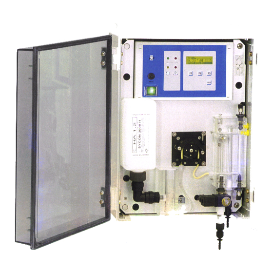
- Page 1 SYCON 3000 C Analytical Instrument to Measure the Carbonate Hardness of Water...
-
Page 2: Table Of Contents
Table of Contents Functional description .......................... 1 Operating displays ..........................2 LED control lamps..........................2 LCD display............................3 INFO displays............................4 Indicator type and hardness unit ...................... 4 Service telephone number ....................... 4 Input states ............................4 Output states ............................ 4 Analysis result counter ........................ - Page 3 4. Parameters of the input functions....................14 Input function "START" ........................14 Delay time Analysis start ......................14 Input function "STOP" ........................14 Delay time Analysis stop ......................14 Input function "Reset relay"......................14 Delay time Delete relay ......................14 Input function "Water meter"...
-
Page 5: Functional Description
The built-in feed valve is closed during the ana- water valve before the input valve is opened. lytical pauses to prevent unnecessary water con- sumption. SYCON 3000 C Water softening plant Analytic al Instrument to Measure the Carbonate Hardness of Water Installation example... -
Page 6: Operating Displays
Operating displays LED control lamps SYCON 3000 C Operating displays LED control lamps LCD - display LED - control lamps 10 m Limit 0 . 9 0 °m g / l > 0.5 STA RT FLUSH Fuse Keys MT 4A Power switch Coloured control lamps indicate the most important operating states: Soft water ( g ree n ) -
Page 7: Lcd Display
Operating displays LCD display SYCON 3000 C LCD display Displays between the analyses Displays during the analyses 5 , 3 1 c b m | 2 * B l a n c v a l u e L i m i t L i m i t 1 7 m g / l 1 7 m g / l... -
Page 8: Info Displays
Operating displays INFO display SYCON 3000 C INFO displays With the help of the INFO key, different information or values can be requested. Modifications will be de- scribed – as far as possible – in the programme section "Changing and reading out the programme data". Only the Service telephone munber can be altered during the display. -
Page 9: Manual Control
Manual control SYCON 3000 C Manual control The three keys F1, F2 and F3 under the display are characterised as softkeys. These keys have a changing function instead of a fixed function. The function that the key has at the moment is shown above the key in the inverse colour scheme in the lower display line. -
Page 10: Messages
Messages SYCON 3000 C Messages If the integrated buzzer is activated in the course of a message, you can delete it by pressing the "HORN" key. The message in the LCD display is only removed when the cause of the message is remedied or a new analysis is started manually. -
Page 11: Input Functions
Input functions SYCON 3000 C Input functions From the 3 available input functions, maximally 2 can be programmed for the two inputs of the analyser in the programme steps 3.1 and 3.2. Each function can only be implemented once. In programme step 3.3, it is determined whether the inputs are to be active with open or closed contact. In programme step 3.3, a delay time can be en- Start analysis tered. -
Page 12: Output Functions
Output funktions SYCON 3000 C Output functions Of the 5 available output functions, maximally 3 can be programmed for the outputs of the analyser. The output function "Permanent signal" is available in 2 different versions. With the output function "Permanent signal 2"... -
Page 13: Recorder Outputs
Recorder outputs SYCON 3000 C Recorder outputs At the recorder outputs RC1 and RC2, line recorders or dot printers with a current input of 0 - 20 mA or 4- 20 mA can be connected. Programming occurs in programme steps 8.1 and 8.2 respectively. Recorder output RC 1 A recorder at this output registers the following states of the analyser: 1. -
Page 14: Changing And Calling Up The Programme Data
Changing and calling up the programme data SYCON 3000 C Changing and calling up the programme data General information on programming and on entering the national language On commissioning the analyser is programmed E N G L I S H according to the desired mode of operation. -
Page 15: Reagents And Limit Value
Changing and calling up the programme data Reagents and limit value SYCON 3000 C 1. Reagents and limit value Indicator type S t e p n o . : 1 . 1 START T y p : C A 9 8 - 1 6 0 m g / l ▼... -
Page 16: Analysis Sequence
Changing and calling up the programme data Analysis sequence SYCON 3000 C 2. Analysis sequence Flush time S t e p n o . : 2 . 1 F l u s h t i m e 6 0 s ▲... -
Page 17: Selection Of The Programmable Input Functions
Changing and calling up the programme data Selection of the programmable input functions SYCON 3000 C 3. Selection of the programmable input functions From the 4 available input functions, maximally 2 can be programmed to the two inputs IN1 and IN2 of the analyser. Each input function can only be used once. -
Page 18: Parameters Of The Input Functions
Changing and calling up the programme data Parameters of the input funktions SYCON 3000 C 4. Parameters of the input functions In line with the selection made in programme step 3.1 and 3.2, supplementary data must be entered in the form of parameters for the inputs IN1 and IN2. Input function "START"... -
Page 19: Selection Of The Programmable Output Functions
Changing and calling up the programme data Selection of the programmable output functions SYCON 3000 C 5. Selection of the programmable output functions Of the 5 available output functions, maximally 3 can be programmed to the outputs OUT1, OUT2 and OUT3 of the analyser. The output function "Perma- nent signal"... -
Page 20: Parameters Of The Output Functions
Changing and calling up the programme data Parameters of the output functions SYCON 3000 C 6. Parameters of the output functions In line with the selection made in programme steps 5.1 to 5.3, supplementary data must be entered in the form of parameters for the outputs OUT 1 to OUT Output function: Pulse signal Output Pulse length... -
Page 21: Output Functions: Permanent Signal 2
Changing and calling up the programme data Parameters of the output functions SYCON 3000 C Output functions: Permanent signal 2 Activation with a limit overrun or underrun and in the event of a fault. Automatic delete function 2 S t e p n o . -
Page 22: Output Function: Signal Relay
Changing and calling up the programme data Parameters of the output functions, Activation of the buzzer SYCON 3000 C Output function: Signal relay Fault messages S t e p n o . : 6 . 9 R F | N I | B V | V H | V L |... -
Page 23: Recorder
Changing and calling up the programme data Recorder SYCON 3000 C 8. Recorder Recorder output RC1 = operational sequence S t e p n o . : 8 . 1 A n a l y s i s a c t i v e ▼... -
Page 24: Entering A Code Number
Changing and calling up the programme data Entering a code number SYCON 3000 C 9. Entering a code number S t e p n o . : 9 . 0 C o d e n u m b e r * * * * ▲... -
Page 25: Service Setting 1 And 2
Service setting 1 and 2 SYCON 3000 C Service setting 1 and 2 With the help of the "KEY" key, activate the key function "SERVICE" for the "F3" key. Press the key function "SERVICE". After approx. 4 seconds the analyser switches into the Service setting 1. You switch into the next service mode by pressing the "▼"... -
Page 26: Test Of The Output Relays
Service setting 2 Test of the output relays SYCON 3000 C Wait approx. 10 to 20 seconds until any air bubbles in the measuring chamber have disappeared. With the help of the potentiometer in the terminal box, adjust the display to a value between 95 % and 105 %. Should this not prove possible, check if the measuring chamber has been filled with clear water. -
Page 27: Installation Of The Instrument
Installation of the instrument Commissioning of the instrument SYCON 3000 C Installation of the instrument 1. Removing the mounting plate 5. Setting up the water outflow Remove the 4 outer fastening screws of the Fit a PVC hose with an interior diameter di- mounting plate, withdraw the mounting plate ameter of 6-7 mm to the hose connector and to the front and remove the rear-side plug... -
Page 28: Dimensions And Drilling Plan For The Assembly
Dimensions and drilling plan for the assembly Measurement diagramme SYCON 3000 C Dimensions and drilling plan for the assembly For the wall mounting of the ana- lyser, the 4 enclosed brackets must be fitted onto the instru- ment with the aid of the 4 screws. Use 8 mm dowels and wood screws of 4.0 x 45 mm for the wall mounting. -
Page 29: Terminal Plan
Terminal plan Internal connections SYCON 3000 C Terminal plan internal signal tone generator Programmable Operation Water functions progress hardness 24 V ~ 500 mA Programmable functions PE PE No Nc No Nc No Nc Protective earth Power in Power out OUT 1 OUT 2 OUT 3... -
Page 30: Notes On Connections
Notes on connections SYCON 3000 C Notes on connections Mains input The mains input voltage can be found on the nameplate. The instrument can be connected with the mains supply permanently or through a mains plug. Example NE 1 If the analyser has a fixed connection with the power supply system and in addition the 22-26 door is closed with a lock, an additional contact-breaking device, e.g. -
Page 31: Relay Outputs
Notes on connections SYCON 3000 C Relay outputs The analyser is equipped with 3 identical relay outputs. It is only through the programming in programme steps 5.1 - 5.3 that they are accorded a specific function. In programme step 5.4, it is determined whether the relay pulls in or drops out when this function is activated. -
Page 32: Recorder Interface
Notes on connections Connection and programming examples SYCON 3000 C Recorder interface Example RC1 Example RC2 The analyser is equipped with 2 analogue outputs. The various instrument states can be extracted as analogue values between 0-20 mA at the output RC RC 1 RC 2 1 and the measured water hardness at the output RC 2. - Page 33 Notes on connections Connection and programming examples SYCON 3000 C Solenoid valve at the output OUT 2 Function: the solenoid valve closes if an excessive water hardness is measured 3 times consecutively or if a malfunction exists. In this way, the water supply to the consumers can be interrupted. Thereafter, no further analyses are conducted.
- Page 34 Connection and programming examples SYCON 3000 C Delete key at IN 2 Function: If a relay has been permanently activated, it can be deactivated again at the instrument or by means of a remote switch (external delete key). Programming: 3.2 = Rest = Function "Reset relay/horn"...
-
Page 35: Replacing Components
Replacing components Instrument maintenance SYCON 3000 C Replacing components 1. Fitting and removing the circulation pump 2. Changing the metering pump hose a. Withdraw the retention pin for the pump a. Tilt the fastening lever of the pressure cover. bracket to the right. b. -
Page 36: Spare Parts List
Spare parts list SYCON 3000 C Spare parts list Analyser casing body Analyser casing cover Control assembly CPU printed board Power unit board Fuse 4 A Fuse 100 mA Terminal box assembly with terminal board Terminal board Circulation pump assembly with cover, magnet and impeller Cover for circulation pump O-ring for cover Motor for circulation pump with magnet... -
Page 37: Technical Data
Technical data Standard: 230V ± 10% 50-60 Hz fuse MT 4T Mains connection: also available in: 115V ± 10% 50-60 Hz fuse MT 4T 24V ± 10% 50-60 Hz fuse MT 4A The instrument is nonvolatile Power consumption 30 VA of the analyser: IP 54 Protective system:...
Need help?
Do you have a question about the SYCON 3000 C and is the answer not in the manual?
Questions and answers