Table of Contents
Advertisement
Quick Links
Advertisement
Table of Contents

Related Manuals for RLS Wacon Aqua Inform Sycon 2501 Fe


Summary of Contents for RLS Wacon Aqua Inform Sycon 2501 Fe
- Page 1 Sycon 2501 Fe On-line Analysis of the Iron Content in Water V24.02.2015...
- Page 3 NTRODUCTION NTRODUCTION We appreciate your purchase of a Limit Analyser type Sycon 2501 Fe for the on- line monitoring of the iron content of water. The Limit Analyser is part of a water treatment plant. Distribution of this manual is intended for the manufacturer and the owner of this plant.
-
Page 4: Table Of Contents
ABLE OF ONTENT ABLE OF ONTENTS 2501 S UMMARY YCON ERIES HAPTER AFETY WARNINGS RECAUTIONS YMBOLS USED HAPTER PECIFICATION AND VERVIEW PECIFICATION AND INTENDED USE → G ENERAL PECIFICATION → T ECHNICAL DATA → M ONITORING CAPABILITIES → W ATER INLET AND OUTLET →... - Page 5 ABLE OF ONTENT HAPTER AINTENANCE AND SERVICE → C HANGING ERISTALTIC OSING → C LEANING OF THE EASURING CHAMBER → C HANGING ARTS → C HANGING EAGENT OTTLE → C HANGING PARE ARTS HAPTER IAGNOSTIC UNCTION → TEST OF → ONTROL UTTON →...
-
Page 6: Summary Sycon 2501 Series
UMMARY YCON ERIES With the Limit Analyser, RLS Wacon offers a very compact and easily operated water analyser for automatic on-line monitoring of water treatment plants. The system controls selectable limit values according to the colorimetric principle. A broad range of functions guarantee reliable field-operation. - Page 7 HAPTER AFETY NSTRUCTIONS HAPTER AFETY WARNINGS AND RECAUTIONS This Chapter explains the dangers, precautionary signs and notes that apply to the handling, installation, wiring and maintenance of the S 2500 series Limit YCON Analyser. These instructions are not a substitute for vocational training. This manual describes the installation and operation of the on-line analyser of type Limit Analyser Fe based on S 2501 series.
- Page 8 AFETY NSTRUCTIONS HAPTER Safety instructions and symbols used In this manual you will find specific safety instructions to indicate the unavoidable residual risks when operating the unit. These residual risks imply dangers to ● People ● Product / Plant / Machinery ●...
- Page 9 HAPTER AFETY NSTRUCTIONS Work on hydraulic and pneumatic equipment ● Maintenance and repair of hydraulic and pneumatic equipment should be carried out by specially trained personnel! ● Before all maintenance and repair work, the pneumatic and hydraulic equipment of the system / machine must be depressurised! ●...
- Page 10 AFETY NSTRUCTIONS HAPTER Storage We recommend storing equipment no longer than a year to avoid loss of the warranty. Store the equipment under the following conditions. ● Cool and dry location. NOTE ● Ambient temperature between 0 and 45 °C. Shipment Shipment consists of: ●...
- Page 11 HAPTER PECIFICATION AND VERVIEW HAPTER PECIFICATION AND VERVIEW The Limit Analyser is used for the automatic monitoring of hardness in water. We recommend that the user read this chapter before installation of the device for safe operation. General Specifications 85 … 264 VAC 47… 63 Hz Power-supply Power consumption 25 VA (in operation)
- Page 12 PECIFICATION AND VERVIEW HAPTER Order numbers for unit and reagent Limit Analyser SYCON 2501 Fe 30-010321 Standard enclosure 33-099005 Reagents 0.03 – 0.6 mg Fe/l 32-080320 Fe-LRS 0.3 – 6.0 mg Fe/l Fe-HRS 32-080330 The system works with one-component reagents with different limit values. Shelf-life of the reagents is 2 years if properly stored (not opened;...
-
Page 13: Specification And Overview
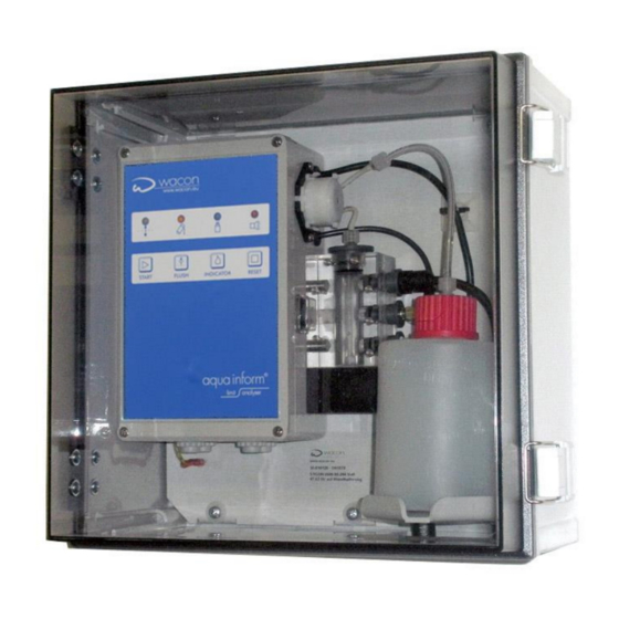
HAPTER PECIFICATION AND VERVIEW 2.2 Overview – limit analyser – configuration . 2.1 OSING ONTROL OSING ATER UTLET PTICAL ATH WITH IGHT OURCE AND EASURING CHAMBER RECEIVER ATER NLET OLENOID VALVE EHIND OTTLE AGNETIC STIRRER EAGENT BOTTLE ATER AMPLE IRECTION OF NLET RESSURE OF ATER... - Page 14 PECIFICATION AND VERVIEW HAPTER – D . 2.2 IMIT NALYSER ISPLAY AND PERATING ANEL LED D ISPLAY EST RESULT REEN ONDITION OWER ONDITION ELLOW NALYSIS ACTIVE ACK OF REAGENT LARM UNIT FAILURE ONTROL UTTONS START START ANALYSIS MANUALLY FLUSH RINSE MEASURING CHAMBER MANUALLY INDICATOR DOSE REAGENT MANUALLY...
- Page 15 HAPTER PECIFICATION AND VERVIEW 2.4 S PARE ARTS Order N Description 33-090 002 Magnetic stirrer 33-090 008 Bottle Adapter 33-090 009 Bottle adapter 33-090 011 Suction lance 33-090 013 Inlet connection ¼" 33-090 014 Solenoid valve 24V complete 33-090 015 Outlet connection 6mm 33-090 016 Bulkhead fitting 6mm...
-
Page 16: Operation Principle
PECIFICATION AND VERVIEW HAPTER 2.5 Operation principle of Sycon 2501 An analysis cycle consists of 5 steps Start delay: When monitoring hot water, it is necessary to cool the water before it can be analysed. A cool water valve can The analysis start can be delayed by between be opened via REL 3. -
Page 17: Functions
HAPTER PECIFICATION AND VERVIEW 2.6 Functions The SYCON 2501 Fe system has the following features: Automatic detection of iron leakage in accordance with limit value reagent used. The monitoring process is fully automated, saving a significant amount of work by eliminating the need for complicated manual procedures. - Page 18 PECIFICATION AND VERVIEW HAPTER The potential free switch of a flow monitor, a timer or any other condition switch can be connected to this input. (→ page 26). When the contacts are open, no analysis will be carried out during the programmed interval. As an alternative, this input can be used as a start input.
-
Page 19: Hapter
HAPTER NSTALLATION AND OMMISSIONING HAPTER NSTALLATION AND OMMISSIONING IMIT NALYSER 3.1 Installation Requirements The analyser shall be used only to determine a parameter in the sample water. Proper operation can only be guaranteed if reagents approved by the (→ page 12 or 27). manufacturer are used Changes to the electrical connections and the programming should only be carried out by a qualified person. - Page 20 NSTALLATION AND OMMISSIONING HAPTER 3.3 Installation in 4 steps The analyser can be mounted with or without protective enclosure. The manufacturer offers a standard enclosure. The mounting and dimensions are described in this guide: Custom-built or tailor made enclosures for the devices of the series Limit Analyser /SYCON 2501 / SYCON 2800 as well as devices with custom names and labels that are technically based on these ranges are not described in detail in this manual.
- Page 21 HAPTER NSTALLATION AND OMMISSIONING Fig. 3.1 Terminal layout and internal connections...
- Page 22 NSTALLATION AND OMMISSIONING HAPTER Fig 3.2 Wiring diagram...
- Page 23 HAPTER NSTALLATION AND OMMISSIONING ► Step IV install a new, full reagent bottle Open the reagent bottle and insert the suction lance into the bottle. Secure the cap by hand. Avoid cross threading (refer also → page 45 "changing reagent bottle"). The reagent bottle is not automatically included with the device.
- Page 24 NSTALLATION AND OMMISSIONING HAPTER Fig. 3.3 Wall mounting without enclosure 276x276 NLET PRESSURE OF SAMPLE WATER 0.5 - 5.0 BAR FLOW DIRECTION OF 1-2 BAR IS WATER SAMPLE RECOMMENDED !!! O UNNEL REDUCE HIGHER → A TMOSPHERIC RESSURE INLET PRESSURE Fig.
- Page 25 HAPTER NSTALLATION AND OMMISSIONING Connection of relay outputs → relay REL1 Exceeded limit terminals 7 / 8 / 9 Signal devices and valves can be switched on when the limit is exceeded. The relay switches as permanent contact or impulse contact to trigger a control system for the regeneration of a water treatment plant.
- Page 26 NSTALLATION AND OMMISSIONING HAPTER Connection of remote signals → ‘IN’ Digital input terminals 16 / 17 An analysis while the water softener is in regeneration may erroneously indicate hardness leakage. An attempt to test with the water feed closed would return either hardness leakage or stagnant water into the feed pipes or a system error due to a lack of flow would be signalled.
-
Page 27: Hapter
HAPTER PERATION AND HAPTER PERATION AND USE 4.1 Summary of limit analysers of Sycon 2501 series Analysers of Sycon 2501 series, type Fe are designed to monitor the limits set for the iron content in water through the use of colorimetric analysis. The one reagents specifically designed for this instrument react with the iron present in the water. -
Page 28: Before Initial Operation
HAPTER PERATION AND 4.2 Before initial operation → Make sure that the steps from chapter 3 (→ page 19) have been performed properly. → Make sure that the unit is securely mounted to a wall or suitable surface. NOTE → If in doubt, consult a specialist or contact your supplier or distributor →... -
Page 29: Programme Switches
HAPTER PERATION AND 4.3 Programme Switches The Limit Analyser has 3 programme switches: Rotary switch for determining the flush time. Rotary switch for determining the delay time. Programme switch for configuring the operating requirements. -
Page 30: Setting The Programme Switches
PERATION AND HAPTER 4.4 Setting the programme switches The operating requirements of the Limit Analyser are programmed using the small DIP switches S1 – S12. Switch off the unit and open the lid of the controller → WARNING supply voltage 85 -264 VAC 47 – 63 Hz →... -
Page 31: Flush Time
HAPTER PERATION AND ► flush time The pre-analysis flush time is programmed using the left hand rotary switch “Flush time“. The range is from 5 seconds to 30 minutes. time time time time 90 s 10 m 18 m 10 s 12 m 20 m 20 s... -
Page 32: Analysis Intervals
PERATION AND HAPTER → The delay time must be calculated on site since it will depend on the water temperatures, the water pressure and the flow conditions of the system. Always begin with a higher delay time and adjust accordingly. ►... -
Page 33: Relay Function
HAPTER PERATION AND First result suppression REL 1 Function No first result 10 11 12 suppression 10 11 12 First result suppressed ► Relay function REL 1 Relay REL 1 signals that the limit has been exceeded. You can choose between an impulse contact (3 und 60 seconds) and a permanent contact. - Page 34 PERATION AND HAPTER ► measurement parameter The analyser can be used to monitor the iron content for two different reagents: → type LRS, range 0-0.6 mg/l → type HRS, range 0-6.0 mg/l NOTE For each reagent 8 limit values can be set through the switches S6 – S8 (see table below and the diagrams on the following page).
- Page 35 HAPTER PERATION AND ► input function The input ‘IN’ can be assigned to two different functions: flow monitoring function: This function is used if an analysis is to be started when a water sample is taken. It is particularly useful for plants that require sporadic tests (e.g.
- Page 36 PERATION AND HAPTER ► Selection of Indicators You can choose between two indicators: Type LRS, range 0 – 0.6 mg Fe/l Type HRS, range 0 - 6 mg Fe/l → see the following diagrams with the displayed programmable limit values (switches S6, S7 und S8).
- Page 37 HAPTER PERATION AND Start up in 5 steps Make sure that the analyser was installed in accordance with chapter 3 (→ page 19) and the program switches were set properly according to the application as described under chapter 4.3/4.4 (→ page 29/30). NOTE step 1 switch on the unit...
- Page 38 PERATION AND HAPTER Operation of the unit → automatic operation Make sure that the analyser was installed in accordance with chapter 3 (→ page 19) and the program switches were set properly according to the application described under chapter 4.3/4.4 (→ page 29/30). →...
- Page 39 HAPTER PERATION AND blue Reagent blue: shortage the LED lights continuously, thus indicating that the reagent level is below 30% blue-flashing: the LED flashes, signalling that the reagent level is below 10%. At the same time, the fault relay REL 2 is activated.
- Page 40 PERATION AND HAPTER 3a. red-flashing alarm message: Red “alarm” LED flashing: malfunction of the LED signals a malfunction of the unit unit → incorrect zero transmission → incorrect measurement all other displays are off → the fault relay is energised 3b.
-
Page 41: Operation Of The Unit
HAPTER PERATION AND Operation of the unit → manual operation Make sure that the analyser was installed in accordance with chapter 3 (→ page 19) and the program switches were set properly according to the application described under chapter 4.3/4.4 (→ page 29/30). →... - Page 42 HAPTER AINTENANCE AND ERVICE MAINTENANCE AND SERVICE HAPTER To ensure long-term functioning of the analyser, it is necessary to clean the measuring-chamber and replace worn parts from time to time depending on the frequency of analyses and general pollution levels. Depending on the load of the appliance, maintenance work should be done at intervals of about 6 months.
- Page 43 HAPTER AINTENANCE AND ERVICE ► Maintenance in 3 steps For routine maintenance in intervals of 4 to 6 months Requirements time: approximately 30 minutes reagent→ page 12 material: depending on limit maintenance set no.1 Art.n 33-090 033 cleaning set Art.n .
- Page 44 AINTENANCE AND ERVICE HAPTER AINTENANCE LEANING OF EASURING CHAMBER REMOVE CLEAN AND REINSTALL → M AINTENANCE 1. First release pressure from water supply line SEE ON PAGE → shut off water supply in the treatment plant → switch on the unit for a while →...
- Page 45 HAPTER AINTENANCE AND ERVICE AINTENANCE EFILL REAGENT AND ESET THE TORAGE OUNTER 1. remove empty reagent bottle → open bottle cap by turning → remove the suction pipe carefully → if reagent fluid leaks, wipe up with a paper towel →...
- Page 46 AINTENANCE AND ERVICE HAPTER Step 1 - step 2A - step 2B - step 3 Annual maintenance in intervals of 6-12 month requirements time: approximately 30 minutes reagent → page 27 material: depending on limit maintenance set no.2 Art.n . 33-090 028 cleaning set Art.n .
- Page 47 HAPTER AINTENANCE AND ERVICE ► Replacing components Please read the notes at the beginning of Chapter 5 →page 42. → Please read the notes in the data sheets of components WARNING Artikel Nr. 33-090 014 HANGE OF OLENOID NLET ALVE 1.
- Page 48 HAPTER IAGNOSTIC UNCTION HAPTER IAGNOSTIC UNCTION A test programme is installed to check the functions of the unit. It is necessary to open the cover of the control (chapter 4.3 → page 29) and to change the position of DIP-switch combination S12: test programme Function 10 11 12...
- Page 49 IAGNOSTIC UNCTION HAPTER Diagnosis in 15 Steps After turning the switch S12 to the ON position, the test steps described below are called up by pressing the START button START IAGNOSIS HECK Press the START button briefly. The LEDs light one after the other: green 1.
- Page 50 IAGNOSTIC UNCTION HAPTER DIP-S IAGNOSIS HECK THE WITCHES Press the START button briefly. Each slide switch S1 to S11 is assigned to a combination of LEDs. 2. X START S1 = GREEN S2 = YELLOW S3 = BLUE S4 = S5 = GREEN YELLOW...
- Page 51 IAGNOSTIC UNCTION HAPTER switch “ ” IAGNOSIS HECK THE FLUSH TIME ROTARY SWITCH LED display position Press the START button briefly. 3. X START → Turn the switch through all 16 positions. every position, combination LEDs will light according to the HEX -code. Green=8 - Yellow=4 - Blue=2 - Red =1 16 position rotary switch...
- Page 52 IAGNOSTIC UNCTION HAPTER “ ” IAGNOSIS HECK THE DELAY TIME ROTARY SWITCH Press the START button briefly. → 4. X Turn the switch through all 16 START positions. every position, combination LEDs will light according to the HEX -code. LED – display as in Diagnosis 4 (above) Green=8 - Yellow=4 - Blue=2 - Red =1 REL 1...
- Page 53 IAGNOSTIC UNCTION HAPTER yellow IAGNOSE HECK OLENOID ALVE Press the START button briefly. 8. X START The inlet valve is checked. → The yellow LED will flash and the inlet valve will open and close at 1 second intervals. LED (A blue IAGNOSE HECK...
- Page 54 IAGNOSTIC UNCTION HAPTER IAGNOSE HECK RANSMISSION Press the START button briefly. 13. X START function zero transmission measurement in the optical path of the measuring-chamber is checked. → the first three LEDs from the left (green + yellow blue yellow + blue) light up →...
- Page 55 IAGNOSTIC UNCTION HAPTER After checking the functions of the unit, exit the test program and change back to analysis mode by switching S10 off. Close the cover of the control box Return the switches to the settings noted at the outset. Close the cover of the control box NOTE Switch S11 has currently no function.
- Page 56 IAGNOSTIC UNCTION HAPTER RLS Wacon GmbH Eduard-Ahlborn-Str. 1 D-31137 Hildesheim Germany Tel. +49 (0) 5121 28 126 0 01.07.2021 IN OUR CONTINUING EFFORT TO IMPROVE OUR Fax. +49 (0) 5121 28 126 99 PRODUCT, INFORMATION IN THIS MANUAL MAY BE CHANGED WITHOUT PRIOR NOTICE info@rls-wacon.de...
Need help?
Do you have a question about the Aqua Inform Sycon 2501 Fe and is the answer not in the manual?
Questions and answers