
Related Manuals for RLS Wacon SYCON Silicate


Summary of Contents for RLS Wacon SYCON Silicate
- Page 1 Operating manual SYCON Silicate Analyser for automated monitoring Silicate concentration in process water...
-
Page 2: Table Of Contents
Display indication during a measurement ....................41 Display of measured value history ......................42 Display Selection menu ..........................42 Display Selection list ............................42 Display with value input ..........................43 Configuration ................................44 Factory settings ..............................44 Configuration Wizard ............................45 © RLS Wacon GmbH ∙ +49 (0)5121 28126 0 ∙ info@rls-wacon.de... - Page 3 Error message E11 Indicator ........................80 Error message E12 Water flow........................80 Error message E13 Optics ..........................80 Notes ..................................81 Appendix ................................82 Spare parts ...............................82 Maintenance sets ............................84 Accessories ..............................85 Declaration of Conformity ..........................86 © RLS Wacon GmbH ∙ +49 (0)5121 28126 0 ∙ info@rls-wacon.de...
-
Page 4: General Information
General information These operating instructions describe the installation and operation of the SYCON Silicate analyzer. Installation and commissioning may only be carried out by an authorized specialist. The device may only be operated under the conditions described in these operating instructions. -
Page 5: Transport
Remove the indicator bottle and close it to prevent the indicator from leaking. Storage Store the analyzer in a dry place at temperatures between 0 - 45 °C and out of direct sunlight. © RLS Wacon GmbH ∙ +49 (0)5121 28126 0 ∙ info@rls-wacon.de... -
Page 6: Sycon Silicate In Detail
Measurement data memory and measurement data log on SD card • no condensation in the optics • Software updates via SD card The SYCON Silicate can be used for automatic monitoring of mixed bed filters. Regular maintenance of the device is necessary for trouble-free operation. Article description Part number... -
Page 7: Device Description
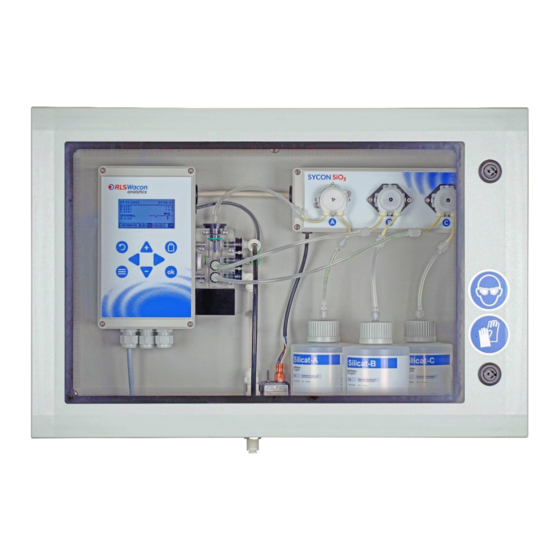
The drain has an outer diameter of 1/4 inch and should be kept as short as possible. All connections are firmly screwed to the housing. To the left of the indicator bottles is the solenoid valve on the supply line. Illustration: Front view with door open © RLS Wacon GmbH ∙ +49 (0)5121 28126 0 ∙ info@rls-wacon.de... - Page 8 SYCON Silicate in detail Illustration: View from below A more detailed description of the components can be found starting on page © RLS Wacon GmbH ∙ +49 (0)5121 28126 0 ∙ info@rls-wacon.de...
-
Page 9: Functional Principle
SYCON Silicate in detail Functional principle The SYCON Silicate is an analyzer for automated monitoring of the silicate concentration in the process water according to the colorimetric method. By adding an indicator to the water sample, a color reaction is generated. The SYCON calculates the silicate concentration in the process water by the colour change of the indicator sample. -
Page 10: Analytical Properties
2 years if stored properly (< 25 °C, dark) indicators Water approx. 2 l sample water per analysis at 2 bar consumption The water consumption varies depending on the inlet pressure and the set flushing time. © RLS Wacon GmbH ∙ +49 (0)5121 28126 0 ∙ info@rls-wacon.de... -
Page 11: Inputs/Outputs
15,000 analyses or Cleaning the measuring chamber (as above), after 12 months of Installation Maintenance kit: Change the peristaltic pump cassettes, operation hoses and seals. Reset of the maintenance counter. © RLS Wacon GmbH ∙ +49 (0)5121 28126 0 ∙ info@rls-wacon.de... -
Page 12: Indicators For Monitoring The Silicate Concentration
Quantity 500 ml Measuring range Art. No. NameIndicator Container Bottles Silicate A Silicate-B 0.3..10 mg/l Silicate 32-010 100 Silicate-C The content of the indicator container is sufficient for approx. 1000 analyses. © RLS Wacon GmbH ∙ +49 (0)5121 28126 0 ∙ info@rls-wacon.de... -
Page 13: Installation
This leads to incorrect measurements. The temperature of the sample water must be between 5 and 40 °C. © RLS Wacon GmbH ∙ +49 (0)5121 28126 0 ∙ info@rls-wacon.de... -
Page 14: Wall Mounting
To open the unit, the available free space should be at least 650 x 500 mm (W x H). Figure: Drilling plan for mounting the analyzer on the wall © RLS Wacon GmbH ∙ +49 (0)5121 28126 0 ∙ info@rls-wacon.de... -
Page 15: Water Connection And Drain
Remove all tools, spare parts or other material required for maintenance before commissioning. • Clean the unit, absorb any spills, and leave the unit in a clean condition. • Check that all safety devices are in place and operational. © RLS Wacon GmbH ∙ +49 (0)5121 28126 0 ∙ info@rls-wacon.de... -
Page 16: Operation With Unpressurized Sample Water
Operation with unpressurized sample water If the sample water is unpressurized, a pressure-controlled diaphragm or submersible pump is required to convey the sample water into the measuring chamber of the analyzer. © RLS Wacon GmbH ∙ +49 (0)5121 28126 0 ∙ info@rls-wacon.de... -
Page 17: Electrical Installation
Display connection Actuator plug LED connection Fuse (5 x 20 mm) 1 A carrier Main switch connection 4 x relay Agitator connection RGB sensor SD card socket Audio signal generator © RLS Wacon GmbH ∙ +49 (0)5121 28126 0 ∙ info@rls-wacon.de... -
Page 18: Connection Of The Supply Voltage
Switched supply voltagebetween L and N 85 - 264 VAC (47...440 3 N power out 4 N power out The maximum connected load of all consumers must not exceed 250 VA / 1 A. Voltage © RLS Wacon GmbH ∙ +49 (0)5121 28126 0 ∙ info@rls-wacon.de... -
Page 19: Connection Of The Relay Outputs
If the measured value of the sample exceeds the limit value 1 set in the device, relay 1 is energized and establishes a connection from COM to NO. In addition, the R1 symbol is highlighted in black in the display. © RLS Wacon GmbH ∙ +49 (0)5121 28126 0 ∙ info@rls-wacon.de... - Page 20 If the measured value of the sample exceeds the limit value 2 set in the device, relay 2 is energized and establishes a connection from COM to NO. In addition, the symbol R2 is highlighted in black in the display. © RLS Wacon GmbH ∙ +49 (0)5121 28126 0 ∙ info@rls-wacon.de...
- Page 21 If the level of one or more indicator bottles falls below 10 %, relay 4 is energized and establishes a connection from COM to NO. In addition, the R4 symbol is highlighted in black in the display. © RLS Wacon GmbH ∙ +49 (0)5121 28126 0 ∙ info@rls-wacon.de...
- Page 22 After the delay time has elapsed, the solenoid valve at the SYCON and the analysis begins. The relay remains energized for the duration of the Analysis switched. For more information, see page 34. © RLS Wacon GmbH ∙ +49 (0)5121 28126 0 ∙ info@rls-wacon.de...
-
Page 23: Power Interface, Rs-485 And Input Contacts
4 - 20 mA Status For further information, please refer to pages 35and 36. RS-485 interface: Modbus (optional) Terminal designation Description 26 (A) Output A RS-485 27 (B) Output B RS-485 © RLS Wacon GmbH ∙ +49 (0)5121 28126 0 ∙ info@rls-wacon.de... - Page 24 A control unit can be connected to the input contact to perform a remote reset in the event of faults and to abort an analysis in progress. For more information, see page 31. © RLS Wacon GmbH ∙ +49 (0)5121 28126 0 ∙ info@rls-wacon.de...
-
Page 25: Connection Of External Components
The connection to external controls is usually made via the potential-free contacts of the relays. Figure: Schematic view of the connection terminals © RLS Wacon GmbH ∙ +49 (0)5121 28126 0 ∙ info@rls-wacon.de... - Page 26 1 to 4 must not exceed 250 VA. The output terminals are switched with the analyzer's power switch and protected by the microfuse. (5 x 20mm) of the device are fused. © RLS Wacon GmbH ∙ +49 (0)5121 28126 0 ∙ info@rls-wacon.de...
-
Page 27: Switch For External Analysis Start
With a permanently connected input contact in Analysis Start mode, analyses are performed permanently. Programming: Menu > Settings > Inputs > Input 1 > Start analysis Figure: Three possible variants for connecting a Schlater for external analysis start © RLS Wacon GmbH ∙ +49 (0)5121 28126 0 ∙ info@rls-wacon.de... -
Page 28: Connection Of A Water Meter For Analyses In The Quantity Interval
(Hall) can lead to incorrect interval quantities due to contact bounce. Programming: Menu > Settings > Inputs > Input 1 > Water meter Programming: Menu > Settings > Analysis > Auto.interval amount © RLS Wacon GmbH ∙ +49 (0)5121 28126 0 ∙ info@rls-wacon.de... -
Page 29: Flow Switch
Programming: Menu > Settings > Inputs > Input 1 > Flow switsch This function must not be confused with the "Start analysis" function by external control. Figure: Three possible variants for connecting a flow switsch © RLS Wacon GmbH ∙ +49 (0)5121 28126 0 ∙ info@rls-wacon.de... -
Page 30: Switchable Interval Reset On (Input 1) With Plc Control
(When using this function, the Sycon must be in automatic mode). No analyses are performed with a permanently connected input contact (INPUT 1) in Interval Reset mode. Programming: Menu > Settings > Inputs > Input 1 > Interval reset © RLS Wacon GmbH ∙ +49 (0)5121 28126 0 ∙ info@rls-wacon.de... -
Page 31: Connection Of A Switch Error Reset To (Input 2)
For this purpose, a switch is connected to the input contact (INPUT 2). This can be a potential-free switch or the relay output of a PLC control or control room. Programming: no programming required for input 2 / (INPUT 2) © RLS Wacon GmbH ∙ +49 (0)5121 28126 0 ∙ info@rls-wacon.de... -
Page 32: Signal Lamp/Horn
1 / output 1 switches back (connection from COM to NC). The next time the limit value is exceeded, relay 1 / output 1 is switched again as a pulse. Programming: Menu > Settings > Outputs > Relay 1 © RLS Wacon GmbH ∙ +49 (0)5121 28126 0 ∙ info@rls-wacon.de... - Page 33 Connection of external components Illustration: Assignment of the terminals when connecting a signal lamp/horn © RLS Wacon GmbH ∙ +49 (0)5121 28126 0 ∙ info@rls-wacon.de...
-
Page 34: Relay Function Analysis Active (Analysis Delay)
Design, integration into the safety chain and installation must be carried out in compliance with the applicable standards and laws. Consult the manufacturer of your steam boiler. © RLS Wacon GmbH ∙ +49 (0)5121 28126 0 ∙ info@rls-wacon.de... -
Page 35: Analog Current Interface
For the current interface type "0 - 20 mA", 0 mA corresponds to 0 mg/l. For the current interface type "4 - 20 mA", 4 mA corresponds to 0 mg/l. © RLS Wacon GmbH ∙ +49 (0)5121 28126 0 ∙ info@rls-wacon.de... -
Page 36: Operating Status Via Analog Current Interface
12.5 mA 13.6 mA Indicator level < 10 % 16.5 mA 16.8 mA Malfunction 0 mA 4 mA The specifications listed here may have a deviation of ± 0.3 mA. © RLS Wacon GmbH ∙ +49 (0)5121 28126 0 ∙ info@rls-wacon.de... -
Page 37: Operation
(The locking pins can only be pulled up and not out). Indicator plug Dosing pump B Indicator plug Dosing pump C Agitator Waste plug Actuator plug LED Feed plug © RLS Wacon GmbH ∙ +49 (0)5121 28126 0 ∙ info@rls-wacon.de... - Page 38 Indicator bottle B 500 ml Indicator bottle C 500 ml Water drain (plug-in connection for plastic hoses with 1/4 inch outer diameter) Water inlet (plug-in connection for plastic hoses with 6mm outer diameter) © RLS Wacon GmbH ∙ +49 (0)5121 28126 0 ∙ info@rls-wacon.de...
-
Page 39: Display And Keypad
Back / Discard input / Abort a running analysis Inserting a new indicator bottle Main menu / Switching between main menu and analysis display Arrow keys for navigation / value input OK / Confirm © RLS Wacon GmbH ∙ +49 (0)5121 28126 0 ∙ info@rls-wacon.de... -
Page 40: Display Menu
Wizard The wizard guides you through all settings in the device and facilitates commissioning. History Displays the history of the last 100 measurements as a diagram. © RLS Wacon GmbH ∙ +49 (0)5121 28126 0 ∙ info@rls-wacon.de... -
Page 41: Display Indication During A Measurement
SD card available Simple analysis start. Press and hold the [OK] button for 3 seconds to start an analysis. The analysis start is possible in manual and automatic mode. © RLS Wacon GmbH ∙ +49 (0)5121 28126 0 ∙ info@rls-wacon.de... -
Page 42: Display Of Measured Value History
The currently selected function is marked in black (start analysis). The black filled circle to the left of the input function indicates which function is currently programmed for input 1. © RLS Wacon GmbH ∙ +49 (0)5121 28126 0 ∙ info@rls-wacon.de... -
Page 43: Display With Value Input
In the Flush Time example below, a flush time between 15 and 1800 seconds can be set. The currently programmed flush time is 120 seconds. After entering a flushing time of 90 seconds, confirmation with the [OK] key overwrites the current flushing time with 90 seconds. © RLS Wacon GmbH ∙ +49 (0)5121 28126 0 ∙ info@rls-wacon.de... -
Page 44: Configuration
Limit value 1 as permanent contact Outputs Relay 2 Measuring range undershot Relay 3 Reporting errors Relay 4 Indicator alarm Reset the factory settings with Programming: Menu > Settings > General > Factory settings © RLS Wacon GmbH ∙ +49 (0)5121 28126 0 ∙ info@rls-wacon.de... -
Page 45: Configuration Wizard
Select [Yes] or [No] with the arrow keys [] and [] and confirm with the [OK] key. [Yes] Exits the automatic mode. [No] Return to the measured value view © RLS Wacon GmbH ∙ +49 (0)5121 28126 0 ∙ info@rls-wacon.de... - Page 46 Do you want to set the date and time? Select [Yes] or [No] with [] and [] and confirm with [OK]. [Yes] Set the date and time. [No] The device keeps the date and time unchanged. © RLS Wacon GmbH ∙ +49 (0)5121 28126 0 ∙ info@rls-wacon.de...
- Page 47 (can be read in the menu > Info) [No] The device retains the previous data. Indicator A Insert a new indicator bottle A and press OK. Insert new indicator bottle A and press the [OK] key. © RLS Wacon GmbH ∙ +49 (0)5121 28126 0 ∙ info@rls-wacon.de...
- Page 48 The pumping process can be cancelled before the time has elapsed by pressing the [OK] key. Make sure that the indicator has been pumped into the measuring chamber without bubbles. © RLS Wacon GmbH ∙ +49 (0)5121 28126 0 ∙ info@rls-wacon.de...
- Page 49 Select [Yes] or [No] with [] and [] and confirm with [OK]. [Yes] The bottle level C is set to 100 %. [No] The previous bottle filling level in % is retained. © RLS Wacon GmbH ∙ +49 (0)5121 28126 0 ∙ info@rls-wacon.de...
- Page 50 Make sure that the sample water is clear and free of bubbles. Flushing time Set the flushing time in the following screen. Press the [OK] key. © RLS Wacon GmbH ∙ +49 (0)5121 28126 0 ∙ info@rls-wacon.de...
- Page 51 OK field in the keyboard and confirm with the [OK] key. Enter the upper limit value 1 which, if exceeded, should switch Limit value 1 relay 1. Press the [OK] key. © RLS Wacon GmbH ∙ +49 (0)5121 28126 0 ∙ info@rls-wacon.de...
- Page 52 Select [Yes] or [No] with [] and [] and confirm with [OK]. [Yes] Analyses are performed at an automatic time interval. [No] Do not perform analyses in the automatic time interval. © RLS Wacon GmbH ∙ +49 (0)5121 28126 0 ∙ info@rls-wacon.de...
- Page 53 These are carried out at 3-minute intervals after a limit value has been exceeded in order to avoid false alarms. Select and confirm with the [OK] key. © RLS Wacon GmbH ∙ +49 (0)5121 28126 0 ∙ info@rls-wacon.de...
- Page 54 An analysis is started as soon as the INPUT 1: Input contact" terminal 13 is bridged to terminal 14. (When using this function, the Sycon must be in automatic mode). © RLS Wacon GmbH ∙ +49 (0)5121 28126 0 ∙ info@rls-wacon.de...
- Page 55 Hall for electronic water meters Select and confirm with the [OK] key. Set the amount of water after which an analysis is to take place. Press the [OK] key. Set the unit. © RLS Wacon GmbH ∙ +49 (0)5121 28126 0 ∙ info@rls-wacon.de...
- Page 56 [NC] Analysis interval paused: Next analysis start is waiting for an open input contact. Select and confirm with the [OK] key. (When using this function, the Sycon must be in automatic mode). © RLS Wacon GmbH ∙ +49 (0)5121 28126 0 ∙ info@rls-wacon.de...
- Page 57 Input 2 (input 2) is used to reset the device in case of an error. Input 2 can be used to reset the device in the event of a device fault. Confirm with [OK] key. © RLS Wacon GmbH ∙ +49 (0)5121 28126 0 ∙ info@rls-wacon.de...
- Page 58 If the value at "Current" corresponds to your wish, you do not need to enter the number again and can immediately move the cursor to the OK field in the keyboard and confirm with the [OK] key. © RLS Wacon GmbH ∙ +49 (0)5121 28126 0 ∙ info@rls-wacon.de...
- Page 59 Select [Analysis] or [Indicator] and press the [OK] key. The relay switches during the analysis. [Indicator] The relay switches when the level falls below the indicator level of 10 % residual content. © RLS Wacon GmbH ∙ +49 (0)5121 28126 0 ∙ info@rls-wacon.de...
- Page 60 0 to 20 mA Status • 4 to 20 mA Status (If Status is selected - see further information on page 36) Select and confirm with the [OK] key. © RLS Wacon GmbH ∙ +49 (0)5121 28126 0 ∙ info@rls-wacon.de...
- Page 61 If the value at "Current" corresponds to your wish, you do not need to enter the number again and can immediately move the cursor to the OK field in the keyboard and confirm with the [OK] key. © RLS Wacon GmbH ∙ +49 (0)5121 28126 0 ∙ info@rls-wacon.de...
- Page 62 The configuration is complete. The wizard is closed. Press the [OK] key. This completes the configuration of the device. If required, individual settings can also be made without the wizard. Programming: Menu > Settings © RLS Wacon GmbH ∙ +49 (0)5121 28126 0 ∙ info@rls-wacon.de...
-
Page 63: Menu Structure
Configuration Menu structure The following is an overview of the menu structure to give you an overview of all the functions of the analyzer. © RLS Wacon GmbH ∙ +49 (0)5121 28126 0 ∙ info@rls-wacon.de... -
Page 64: Operation
Service Functions for maintenance, diagnosis and indicator change Wizard Setup wizard for guided parameterization of the device History Display of the last 100 measurement results with date and time © RLS Wacon GmbH ∙ +49 (0)5121 28126 0 ∙ info@rls-wacon.de... -
Page 65: Info Display
(Settings > General > Export settings). After inserting the SD card into the new device, the settings can be imported (Settings > General > Import settings). The measurement log on the SD card is continued by the new device. © RLS Wacon GmbH ∙ +49 (0)5121 28126 0 ∙ info@rls-wacon.de... -
Page 66: Sd Card
For more information about importing a software update, see page 76. We recommend deleting the file from the SD card again after installing an update. © RLS Wacon GmbH ∙ +49 (0)5121 28126 0 ∙ info@rls-wacon.de... - Page 67 Is generated when the device configuration is exported. MAIN.CSS Data Style file associated with INDEX.HTM for display as DIN A4 page. Is generated when exporting the device configuration. © RLS Wacon GmbH ∙ +49 (0)5121 28126 0 ∙ info@rls-wacon.de...
-
Page 68: Maintenance And Service
15,000 analyses Install cleaning and maintenance kit or after 12 months © RLS Wacon GmbH ∙ +49 (0)5121 28126 0 ∙ info@rls-wacon.de... -
Page 69: Cleaning The Measuring Chamber
The blue dosing O-ring (D) on the indicator plugs must not be lubricated with technical Vaseline. On the other hand, the O-rings (5 x J and 1 x C) must be lubricated with technical Vaseline before insertion into the measuring chamber. © RLS Wacon GmbH ∙ +49 (0)5121 28126 0 ∙ info@rls-wacon.de... - Page 70 [No] The previous bottle filling level in % is retained. • Rinse the measuring chamber again (programming: Menu > Service > Manual rinsing). The device is ready for operation again. © RLS Wacon GmbH ∙ +49 (0)5121 28126 0 ∙ info@rls-wacon.de...
-
Page 71: Change Of Peristaltic Pump Cassettes, Hoses And Seals
(The light rod plug belongs to the optical measuring section and must not be scratched). • Remove the o-rings (6 x J, 1 x C, and 3 x D) from the plugs. See Spare Parts Fig. on page 82 © RLS Wacon GmbH ∙ +49 (0)5121 28126 0 ∙ info@rls-wacon.de... - Page 72 See the pictures on pages 3782for the correct positions of the hose pump cassettes.) • Insert the new suction lances into the bottle adapters. • Connect the new hoses. See the illustration on page 37 The hoses must not be twisted. © RLS Wacon GmbH ∙ +49 (0)5121 28126 0 ∙ info@rls-wacon.de...
- Page 73 After replacing the peristaltic pump cassettes, hoses and seals, it is essential to reset the maintenance counter, only then can the SYCON safely and reliably remind you of the next maintenance. © RLS Wacon GmbH ∙ +49 (0)5121 28126 0 ∙ info@rls-wacon.de...
-
Page 74: Changing The Indicator Bottle
[Yes] The bottle level is set to 100 %. • Rinse the measuring chamber again (programming: Menu > Service > Manual rinsing). The device is ready for operation again. © RLS Wacon GmbH ∙ +49 (0)5121 28126 0 ∙ info@rls-wacon.de... -
Page 75: Calibrating The Device
Close the control unit again. Make sure that the ribbon cable between the display board and the main board has not come loose. • Dispose of the battery at a collection point for batteries. © RLS Wacon GmbH ∙ +49 (0)5121 28126 0 ∙ info@rls-wacon.de... -
Page 76: Software Update
This counter can be used to assess the function of a system. The number of bad measurements should be significantly smaller than the number of good measurements. The counters can be reset in the menu. Programming: Menu > Service > Good/Bad counter © RLS Wacon GmbH ∙ +49 (0)5121 28126 0 ∙ info@rls-wacon.de... -
Page 77: Diagnostic Functions
In the other case, a fault of the motor or the main board is possible. To exit, move the cursor to Exit and press the [OK] key. © RLS Wacon GmbH ∙ +49 (0)5121 28126 0 ∙ info@rls-wacon.de... -
Page 78: Indicator B
Pressing the [OK] key increases the output current by 2 mA each time until the maximum value of 20 mA is reached. To exit, move the cursor to Exit and press the [OK] key. © RLS Wacon GmbH ∙ +49 (0)5121 28126 0 ∙ info@rls-wacon.de... -
Page 79: Input 1 And 2
For INPUT 2, connect the COM terminal of the multimeter to terminal 28 and the Volt terminal of the multimeter to terminal 29. Press the [OK] key to exit. The diagnostic mode is finished. © RLS Wacon GmbH ∙ +49 (0)5121 28126 0 ∙ info@rls-wacon.de... -
Page 80: Error Analysis
Check the correct position of the actuator plug. • Check the color sensor in the diagnostic menu. • 0 mA is output at the current output if the type "Value" is set at the current interface. © RLS Wacon GmbH ∙ +49 (0)5121 28126 0 ∙ info@rls-wacon.de... -
Page 81: Notes
Notes © RLS Wacon GmbH ∙ +49 (0)5121 28126 0 ∙ info@rls-wacon.de... -
Page 82: Appendix
Appendix Spare parts © RLS Wacon GmbH ∙ +49 (0)5121 28126 0 ∙ info@rls-wacon.de... - Page 83 Connecting cable solenoid valve multi-pump system 33-000 036 Connecting cable pump unit multi-pump system 33-000 037 Connecting cable actuator 33-000 013 For more information, see chapter Spare parts > Maintenance sets. © RLS Wacon GmbH ∙ +49 (0)5121 28126 0 ∙ info@rls-wacon.de...
-
Page 84: Maintenance Sets
Appendix Maintenance sets The SYCON Silicate operates largely maintenance-free. A maintenance set is available for the analyzer. It is recommended to change the hose pump cassettes, hoses and O-rings after 15,000 analyses or 12 months. The analyzer will show a maintenance notice on the display after the maintenance interval has expired. -
Page 85: Accessories
Depending on the temperature of the water and the cooling water, upstream coolers are offered for flow-through cooling. Further information and data sheets can be found on our website. © RLS Wacon GmbH ∙ +49 (0)5121 28126 0 ∙ info@rls-wacon.de... -
Page 86: Declaration Of Conformity
Appendix Declaration of Conformity © RLS Wacon GmbH ∙ +49 (0)5121 28126 0 ∙ info@rls-wacon.de... - Page 87 Managing Directors: Dr. Claudia Rudolph, Dr. Sascha Matern Register court: Local court Hildesheim Registration number: HRB 203 391 VAT ID: DE240123142 Photo back: Vitali Vidnevski (employee RLS Wacon GmbH), 2015 Changes and errors excepted 22.09.2021 © RLS Wacon GmbH ∙ +49 (0)5121 28126 0 ∙ info@rls-wacon.de...
- Page 88 © RLS Wacon GmbH ∙ +49 (0)5121 28126 0 ∙ info@rls-wacon.de...
Need help?
Do you have a question about the SYCON Silicate and is the answer not in the manual?
Questions and answers