Table of Contents
Advertisement
Quick Links
®
XBe e - PRO
Overview
Interfacing Protocol
P r o d u ct M a n u a l
For XBee-PRO 900HP RF Modem Part Numbers:
XM-M92-2P...
XM-M92-4P...
XM-M92-UP...
9 0 0 M H z St a n d- a lon e RF M ode m s by D igi I n t e r n a t ion a l I n c.
D igi I n t e r n a t ion a l
World Headquarters
11001 Bren Road East
Minnetonka, MN 55343
Phone: 952-912-3444 or
877-912-3444
Fax: 952-912-4952
9 0 0 H P RS- 2 3 2 / RS- 4 8 5 / USB RF M ode m
90002200_A
2013.12.23
Advertisement
Table of Contents

Related Manuals for Digi XBee-PRO XM-M92-2P Series


Summary of Contents for Digi XBee-PRO XM-M92-2P Series
- Page 1 ® XBe e - PRO 9 0 0 H P RS- 2 3 2 / RS- 4 8 5 / USB RF M ode m Overview Interfacing Protocol P r o d u ct M a n u a l For XBee-PRO 900HP RF Modem Part Numbers: XM-M92-2P...
-
Page 2: 5 ( 2 - W Ir E ) Ope R A T Ion 1
XBee‐PRO® 900HP RS‐232/RS‐485/USB RF Modem‐ Product Manual © 2 0 1 3 D igi I n t e r n a t ion a l I n c. All r igh t s r e se r ve d No part of the contents of this manual may be transmitted or reproduced in any form or by any means without the written permission of Digi International Inc. 900HP RF Modem is a trademark of Digi International Inc. ® XBee‐PRO Technical Support: Phone: (866) 765‐9885 toll‐free U.S.A. and Canada (801) 765‐9885 Worldwide... -
Page 3: Table Of Contents
Limited Modular Approval FCC-approved Antennas I C ( I n du st r y Ca n a da ) Ce r t ifica t ion Appe ndix B: Addit ion a l I nfor m a t ion 2 3 © 2013 Digi International Inc. iii... -
Page 4: Overview Of The 900Hp Rf Modem
When a system is connected to the XBee-PRO 900HP RF Modem, it can transmit and receive data from multiple radios on the same wireless network. This is achieved by using Digi’s XBee-PRO 900HP RF Module. This manual is not a comprehensive manual that provides a full description of the 900HP RF Modem. -
Page 5: Worldwide Acceptance
FCC Appr ove d (U.S.A) Refer to Appendix A for FCC Requirements. ® ® Systems that include XBee /XBee-PRO 900HP RF modems inherit Digi Certifications. ISM (Industrial, Scientific and Medical) 900 GHz frequency band Manufactured under I SO 9 0 0 1 :2 0 0 0 registered standards ®... -
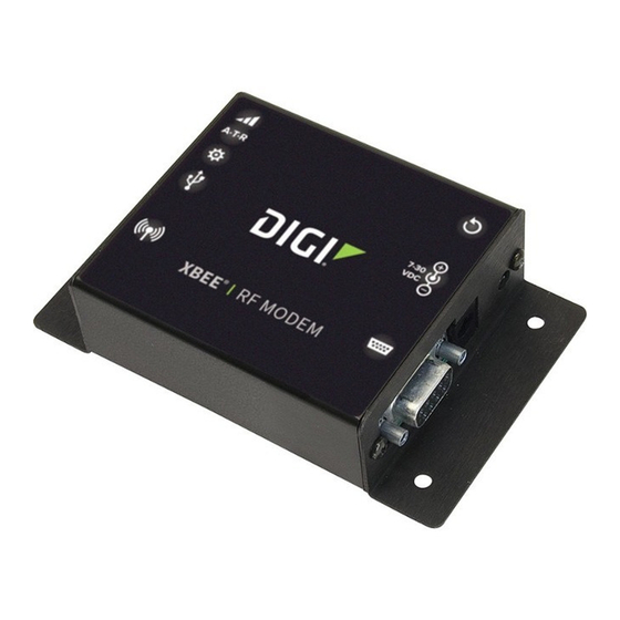
Page 6: Ex T E R N A L I N T E R Fa Ce Of T H E 9 0 0 H P Rf M Ode M
1 - 0 1 c. RS- 2 3 2 Re se t Bu t t on The reset button resets (re-boots) the XBee-PRO 900HP RF Modem. This button only applies when using the configuration tabs of Digi’s X- CTU Software. - Page 7 1 - 0 3 d. RS- 4 8 5 Re se t Bu t t on The reset button resets (re-boots) the XBee-PRO 900HP RF Modem. This button only applies when using the configuration tabs of Digi’s X- CTU Software.
- Page 8 1 - 0 5 c. USB Re se t Bu t t on The reset button resets (re-boots) the XBee-PRO 900HP RF Modem. This button only applies when using the configuration tabs of Digi’s X- CTU Software. 1 - 0 6 a . USB RSSI LED s Figure 1‐06.
-
Page 9: Rf M Ode M Sym Bols
XBee‐PRO® 900HP RS‐232/RS‐485/USB RF Modem‐ Product Manual 1 .4 . RF M ode m Sym bols The following symbols are found on top of the RF Modem. The description of the symbol is next to the symbol. 9 © 2013 Digi International Inc. ... -
Page 10: I Nt E R Fa Cin G Pr Ot Ocol 1
Refer to the Serial Communications and CS Command sections for more information Optional power input (protection circuitry Ring Indicator to prevent back flow from other power sources internal to the board) 10 © 2013 Digi International Inc. ... -
Page 11: Rs-232 Wiring Diagram
2 .1 .2 . RS- 2 3 2 W ir in g D ia gr a m Figure 2‐02. RS‐232 Device DTE Device (male DB‐9 connector) wired to a DCE RF modem (female DB‐9) XBee‐PRO RF Modem D CE RF M ode m t o a D CE RS- 2 3 2 D e vice Figure 2‐03. DCE RF Modem (female DB‐9 connector) wired to an RS‐232 DCE Device (male DB‐9) XBee‐ PRO RF Modem 11 © 2013 Digi International Inc. ... - Page 12 DO buffer to the host device for the RS-485 interface. In the event that the parameter is accidentally changed, which would halt RS-485 communication, a USB mini cable should be plugged into the modem to reconfigure it. You can reconfigure by using Digi’s X-CTU.
-
Page 13: Rs-485 Pin Signals
Optional power input (protection circuitry Power Signal to prevent back flow from other power sources internal to the board). 3, 4 Not Used 2 .2 .2 . RS- 4 8 5 W ir in g D ia gr a m Figure 2‐06. RF Modem in an RS‐485 (2 wire) half duplex 13 © 2013 Digi International Inc. ... - Page 14 DO buffer to the host device for the RS-485/422 interface. In the event that the parameter is accidentally changed, which would halt RS-485 communication, a USB mini cable should be plugged into the modem to reconfigure it. You can reconfigure by using Digi's X-CTU.
-
Page 15: Rs-485 Pin Signals
Optional power input (protection circuitry Power Signal to prevent back flow from other power sources internal to the board) 2 .3 .2 . RS- 4 8 5 W ir in g D ia gr a m s Figure 2‐08. RF Modem in an RS‐485 (4‐wire) environment 15 © 2013 Digi International Inc. ... -
Page 16: Rs-485/422 Connection Guidelines
Select wires so that TX+ and TX-are connected to a twisted pair. Likewise, select wires so that RX+ and RX- are connected to a twisted pair. (For example, tie the green and white/green wires to TX+ and TX-). This reduces the amount of noise on the data line. 16 © 2013 Digi International Inc. ... -
Page 17: Usb Ope R A T Ion 1
Power the RF modem Negative Data Line Transmit data to and from the RF modem Positive Data Line Transmit data to and from the RF modem Permits distinction of host connection from slave Not connected connection Ground Signal Ground 17 © 2013 Digi International Inc. ... -
Page 18: Appe Ndix A: Age N Cy Ce R T Ifica T Ion
900HP RS-232/RS-485/USB RF Module has been certified by the FCC for use with other products without any further certification (as per FCC section 2.1091). Modifications not expressly approved by Digi could void the user's authority to operate the equipment. I M PORTAN T: OEMs must test final product to comply with unintentional radiators (FCC section 15.107 and 15.109) before declaring compliance of their final product to Part 15 of the FCC Rules. -
Page 19: Fcc-Approved Antennas
Fix e d Ba se St a t ion a n d M obile Applica t ion s Digi RF modules are pre-FCC approved for use in fixed base station and mobile applications. When the antenna is mounted at least 20cm (8") from nearby persons, the application is considered a mobile application. - Page 20 An t e n n a Opt ion s: 9 0 0 M H z An t e nn a List in gs The antennas in the tables below have been approved for use with this product. Digi does not carry all of these antenna variants.
- Page 21 Fixed / Mobile A09-Y8 4 Element Yagi 8.1 dBi Fixed / Mobile A09-Y9 4 Element Yagi 9.1 dBi Fixed / Mobile A09-Y10 5 Element Yagi 10.1 dBi Fixed / Mobile A09-Y11 6 Element Yagi 11.1 dBi Fixed / Mobile 21 © 2013 Digi International Inc. ...
- Page 22 Industrie Canada. Dans le but de réduire les risques de brouillage radioélectrique à l'intention des autres utilisateurs, il faut choisir le type d'antenne et son gain de sorte que la puissance isotrope rayonnée équivalente (p.i.r.e.) ne dépasse pas l'intensité nécessaire àl'établissement d'une communication satisfaisante. 22 © 2013 Digi International Inc. ...
-
Page 23: Appe Ndix B: Addit Ion A L I Nfor M A T Ion 2
5-years from the date of pur- chase. In the event of a product failure due to materials or workmanship, Digi will repair or replace the defective product. For warranty service, return the defective product to Digi Inter- national, shipping prepaid, for prompt repair or replacement.
Need help?
Do you have a question about the XBee-PRO XM-M92-2P Series and is the answer not in the manual?
Questions and answers