Table of Contents
Advertisement
Instruction Manual
D100315X012
August 2019
Type 63EG Relief Valve or
Backpressure Regulator
!
Failure to follow these instructions or
to properly install and maintain this
equipment could result in an explosion
and/or fire causing property damage and
personal injury or death.
Fisher™ relief valves must be installed,
operated and maintained in accordance
with federal, state and local codes, rules
and regulations and Emerson Process
Management Regulator Technologies,
Inc. (Emerson™) instructions.
If a leak develops or if the outlet
continually vents gas, service to the
unit may be required. Failure to correct
trouble could result in a hazardous
condition. Only a qualified person must
install or service the unit.
Call a gas service person to service the
unit. Only a qualified person must install
or service the regulator.
Introduction
Scope of the Manual
This instruction manual provides instructions
for the installation, maintenance and parts
ordering information for a Type 63EG relief
valve or backpressure regulator with either a
Type 6358, 6358B, 6358EB or 6358EBH pilot and
a Type 1098-63EGR relief valve with a Type 6358B
pilot. Instructions and parts ordering information for the
optional Type 252 or P590 Series pilot supply filters
and any other equipment used with these valves are
found in separate manuals.
WARNING
Types 63EG and 1098-63EGR
W6955
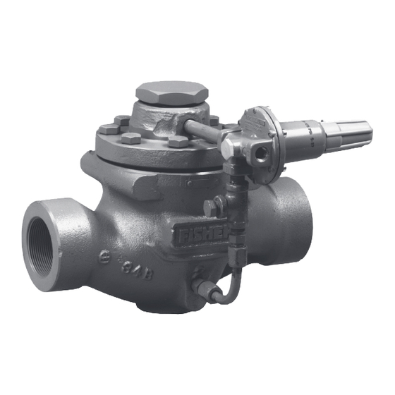
Figure 1. Type 63EG Relief Valve or Backpressure Regulator
W3003-1*
Figure 2. Type 1098-63EGR Relief Valve
Advertisement
Table of Contents

Related Manuals for Emerson 63EG


Summary of Contents for Emerson 63EG
- Page 1 If a leak develops or if the outlet W6955 continually vents gas, service to the Figure 1. Type 63EG Relief Valve or Backpressure Regulator unit may be required. Failure to correct trouble could result in a hazardous condition. Only a qualified person must install or service the unit.
-
Page 2: Specifications
Types 63EG and 1098-63EGR Specifications Specifications for various Types 63EG and 1098-63EGR constructions are listed on Specifications section and Tables 1 to 4. The specifications for a given construction as it originally comes from the factory are stamped on nameplates located on the main valve body and the upper diaphragm case of the actuator for a Type 1098-63EGR construction. -
Page 3: Product Description
There is no service. The Type 63EG is also suitable for throttling constant bleed with this construction which is useful for backpressure or bypass applications. The main valves... - Page 4 Types 63EG and 1098-63EGR Table 2. Minimum and Maximum Differential Pressures TYPE 63EG WITH TYPE 1098 TYPE 63EG SIZE 40 ACTUATOR MAIN Minimum Minimum MAIN VALVE MAIN VALVE BODY SIZE VALVE Differential Maximum Differential Maximum SPRING RANGE SPRING PART SPRING...
-
Page 5: Installation
To avoid injury or damage, install a 2. A Type 63EG or 1098-63EGR may be installed Type 63EG or 1098-63EGR relief valve in any orientation, as long as flow through it... - Page 6 PILOT VALVE PLUG MAIN SPRING PILOT EXHAUST E0101 MAIN VALVE INLET PRESSURE OUTLET PRESSURE/EXHAUST ATMOSPHERIC PRESSURE LOADING PRESSURE Figure 5. Type 63EG Operational Schematic MAIN VALVE SPRING VALVE STEM TYPE 6358B PILOT PILOT EXHAUST PILOT CONTROL SPRING PILOT VALVE PLUG ACTUATOR DIAPHRAGM...
-
Page 7: Startup And Adjustment
WARNING the pilot starts-to-discharge. The set pressure of a unit is adjusted by changing the control spring Types 63EG and 1098-63EGR relief compression on the pilot. valves vent gas from the main valve outlet and from the pilot exhaust. In 8. -
Page 8: Maintenance
(key 4 or 17, Figure 10 or 11) will be replaced if the body. exposed surfaces of the trim package or body interior will be inspected or cleaned. Key numbers for both the complete Type 63EG main valve and its trim package... - Page 9 Install the trim package and PORT A secure it evenly with the cap screws or hex nuts. (EXHAUST) With a Type 63EG main valve, install the pilot and its pipe nipple and connect the pilot supply tubing. PORT C (LOADING)
- Page 10 Install the body flange on the body and secure it evenly with the cap screws or hex nuts. With a Type 63EG main valve, install the pilot and its pipe nipple and connect the pilot tubing.
- Page 11 Types 63EG and 1098-63EGR 12. Being careful not to cut the stem O-ring with the 5. Lubricate both stem O-rings (key 6) and wiper stem threads, install the indicator fitting (key 5) ring (key 57). Install them with the stem bearings down over the indicator stem (key 10) until resting (key 56) in the bonnet (key 3).
-
Page 12: Parts Ordering
Note Parts Ordering In step 3, if installing a different size Each Type 63EG or 1098-63EGR relief valve is restriction, be sure to remove the code assigned a serial number or FS number which can be letter on the bottom of the pilot and found on the nameplates. -
Page 13: Parts List
38A8872X062 keys 2, 11, 9, 16, 13 and Nitrile (NBR) elastomers) NPS 4 / DN 100 38A8867X012 Type 63EG with Steel Body Flange NPS 4 / DN 100 (NACE) 38A8867X032 10 to 40 psig / 0.69 to 2.76 bar, NPS 6 / DN 150... - Page 14 Types 63EG and 1098-63EGR Description Part Number Description Part Number Gasket, composition Valve Body (continued) NPS 1 / DN 25 14A6785X012 NPS 1 / DN 25 for oxygen service 14A6785X052 PN 25, NPS 8 X 6 / DN 200 x 150...
- Page 15 Types 63EG and 1098-63EGR Description Part Number Description Part Number Cage (continued) Spring Quick Opening, 316 Stainless steel Type 63EG (continued) NPS 1 / DN 25 GF03315X012 85 to 400 psig / 5.86 to 27.6 bar NPS 2 / DN 50...
- Page 16 NPS 2 / DN 50 14A5686X072 316 Stainless steel (NACE) NPS 3 / DN 80 1V3269X0082 NPS 1 / DN 25 (for Type 63EG) 17B7565X022 NPS 4 / DN 100 14A5688X112 NPS 1 / DN 25 (for Type 1068-63EGR) 14A6780X022...
- Page 17 14A6983X022 Connector NPS 2, 3 or 4 / DN 50, 80 or 100 14A9684X012 (2 required with Type 63EG and 1 required NPS 2, 3 or 4 / DN 50, 80 or 100 (NACE) 14A9684X032 with Type 1098-63EGR) - - - - - - - - - - -...
- Page 18 Types 63EG and 1098-63EGR Type 1098 Actuators 6358 Series Pilot (Figures 14 and 15) (Figure 13) (continued) Description Part Number Description Part Number Parts Kit (included are keys 4, 5, 13, 14, 19, 36, 37 and P590 Series Filter, keys 2 and 7)
- Page 19 Types 63EG and 1098-63EGR Description Part Number Description Part Number Control Spring O-ring (for Type 6358EB only) 10A7777X012 Type 6358 Vent Assembly, Type Y602X1-A12 (2 required) 27A5515X012 10 to 40 psig / 0.69 to 2.76 bar, Yellow 1E392527022 35 to 125 psig / 2.41 to 8.62 bar, Red...
- Page 20 Types 63EG and 1098-63EGR 35A3174-A COMPLETE CAST IRON MAIN VALVE ASSEMBLY 25A3169_B QUICK-CHANGE TRIM PACKAGE ASSEMBLY Figure 10. Type 63EG Main Valve without Travel Indicator Assembly...
- Page 21 Types 63EG and 1098-63EGR 35A3167-E 25A3170 COMPLETE CAST IRON MAIN VALVE ASSEMBLY QUICK-CHANGE TRIM PACKAGE ASSEMBLY Figure 11. Type 63EGR Main Valve with Travel Indicator Assembly 25A3178_B 35A3179-C TYPE 63EG MOUNTING PARTS TYPE 1098-63EGR MOUNTING PARTS Figure 12. Mounting Parts Assembly...
- Page 22 Types 63EG and 1098-63EGR 34A5692 Figure 13. Type 1098 Actuator Assembly A6920_6365 B2619-2_6365 TYPE 6358 PILOT INTERIOR VIEW TYPE 6358B PILOT INTERIOR VIEW APPLY SEALANT (S) Figure 14. Types 6358 and 6358B Pilots Assemblies...
- Page 23 Types 63EG and 1098-63EGR 48B4849_A 48B3431_A TYPE 6358EB PILOT INTERIOR VIEW TYPE 6358EBH PILOT INTERIOR VIEW 48B3430_A TYPE 6358EB PILOT WITH DIAPHRAGM LIMITER FOR 180 TO 350 PSIG / 12.4 TO 24.1 BAR SET PRESSURE RANGE INTERIOR VIEW APPLY SEALANT (S)
- Page 24 Technologies, Inc. All rights reserved. 08/19. Emerson Automation Solutions The Emerson logo is a trademark and service mark of Emerson Electric Co. All other marks are the property of their prospective owners. Fisher™ is a mark owned by Fisher Controls International LLC, a...
Need help?
Do you have a question about the 63EG and is the answer not in the manual?
Questions and answers