Table of Contents
Advertisement
Quick Links
UM2999
User manual
Evaluation board for FDA803S and FDA903S power amplifiers
Introduction
This document describes how to use the evaluation board in order to check FDA803S and FDA903S device's performance.
For any other information and deeper details, refer to the FDA803S and FDA903S datasheets.
UM2999 - Rev 1 - March 2022
www.st.com
For further information contact your local STMicroelectronics sales office.
Advertisement
Table of Contents

Related Manuals for ST FDA803S


Summary of Contents for ST FDA803S
- Page 1 Evaluation board for FDA803S and FDA903S power amplifiers Introduction This document describes how to use the evaluation board in order to check FDA803S and FDA903S device’s performance. For any other information and deeper details, refer to the FDA803S and FDA903S datasheets.
-
Page 2: Ordering Information
UM2999 Ordering information Ordering information The board can only be ordered with the FDA903S mounted on it. The ordering information is shown in Table Table 1. Ordering information Order code Device mounted on the board EVAL-FDA903S-SA FDA903S UM2999 - Rev 1 page 2/21... -
Page 3: General Information
This evaluation board/kit is intended for use as ENGINEERING DEVELOPMENT, DEMONSTRATION, OR EVALUATION PURPOSES ONLY and is not considered by ST Microelectronics to be a finished end-product fit for general consumer use. People handling the product(s) must have electronics training and observe good engineering practice standards. -
Page 4: Board Description
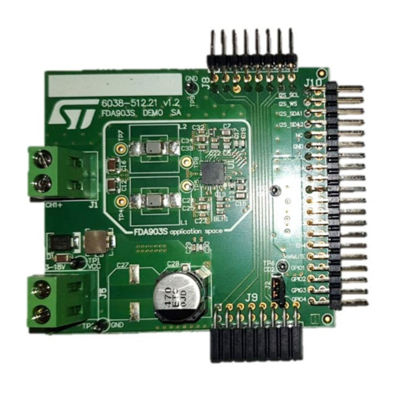
Board description The board features a single channel Class-D amplifier able to deliver up to 10 W (14.4 V at 4 Ω), based on the FDA903S (or FDA803S) and is intended to demonstrate the device capabilities. Figure 1. Top view Figure 2. -
Page 5: Board Connection
UM2999 Board connection Board connection The board can be connected directly to other ST modules such as the Extend Board Mini A2 and MiniA2 via connector J10. Figure 3. FDA903S Demo SA board + Extend board MiniA2 + Mini A2 board... -
Page 6: Connectors And Connections
UM2999 Board options 3.1.1 Connectors and connections Power supply The amplifier power supply (VCC) with a voltage value between 3.3 V and 18 V can be connected to the J5 terminal as shown by the markings on the board. Outputs The amplifier outputs are connected to the J1 terminals. -
Page 7: Startup Sequence
S slave, so the clock must be provided by the signal source) Load the device file (.dev) provided by ST Load the default register setting file (.cfg), if available. If no .cfg file is available, the configuration set in the .dev file is applied. -
Page 8: Quick Start Guide
Attention: It is not allowed to supply the VCC power line of the FDA803S Demo SA from the MiniA2 connector (VBAT) side.Consequently, the 3 resistors (R12, R13, R146) must not all be mounted at same time. UM2999 - Rev 1... -
Page 9: Gui Setup
GUI setup GUI setup • Unzip the device file (“Mini A2 FDA803S-*.zip” or “Mini A2 FDA903S-*.zip”) in the GUI installation folder “.\AccordoGUIFDAXXX\Devices\”. It includes the amplifier’s specific registers description (FDA803S.dev or FDA903S.dev) and if available, the configuration file (registers best settings, FDAx03S_I2Cbest_Setting.cfg). -
Page 10: Device Setup For Playback
UM2999 Device setup for playback Device setup for playback • Turn the device on with an I S clock present: – Click the buttons “channel conf.” followed by “Write all“ to apply the settings loaded from the “FDAx03S_I2Cbest_Setting.cfg” file; – Click the “PLAY”... -
Page 11: Board Schematic
UM2999 Board schematic Board schematic Figure 6 shows the schematics of the “6038-506.20 v1.0 FDA803S DEMO SA“ board. Figure 6. 6038-506.20 v1.0 FDA803S DEMO SA schematic MINI A2 STD CONNECTOR PCB NOTE: Place all these components near J10 connector I2S_SCL... -
Page 12: Bill Of Materials
UM2999 Bill of materials Bill of materials The list provided here shows all the components (including parts necessary for this board but not required when the IC is used in a real project) used to assemble the board described in this manual, with which performance measurements have been performed. - Page 13 TP1, TP2, terminal TP3, TP6, 20-2137 Assembly - 1.04 1x10 W Class D digital input 18 V 45 W QFN32 FDA903S / FDA803S amplifier UNMOUNTED COMPONENTS C1, C2, C3, C4, C8, C9, SMD Capacitor 0603 C10, C11 SMD Electrolytic 470 μF 25 V d10h10.2...
-
Page 14: Board Layout
UM2999 Board layout Board layout Figure 7. Assembly Top Figure 8. Top layer UM2999 - Rev 1 page 14/21... -
Page 15: Figure 9. Layer 2
UM2999 Board layout Figure 9. Layer 2 Figure 10. Layer 3 UM2999 - Rev 1 page 15/21... -
Page 16: Figure 11. Bottom Layer
UM2999 Board layout Figure 11. Bottom layer Figure 12. Assembly Bottom UM2999 - Rev 1 page 16/21... -
Page 17: Revision History
UM2999 Revision history Table 3. Document revision history Date Version Changes 22-Mar-2022 Initial release. UM2999 - Rev 1 page 17/21... -
Page 18: Table Of Contents
UM2999 Contents Contents Ordering information ............. . 2 General information . - Page 19 UM2999 List of tables List of tables Table 1. Ordering information..............2 Table 2.
- Page 20 6038-506.20 v1.0 FDA803S DEMO SA schematic ........
- Page 21 ST’s terms and conditions of sale in place at the time of order acknowledgment. Purchasers are solely responsible for the choice, selection, and use of ST products and ST assumes no liability for application assistance or the design of purchasers’...
Need help?
Do you have a question about the FDA803S and is the answer not in the manual?
Questions and answers