Table of Contents
Advertisement
Service
Manual
• For purposes of improvement, specifications and design are subject to change without notice.
• Please use this service manual with referring to the operating instructions without fail.
• Some illustrations using in this service manual are slightly different from the actual set.
S0314-0V01DM/DG1108
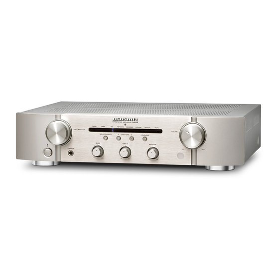
PM6004
Copyright 2011 D&M Holdings Inc. All rights reserved.
WARNING: Violators will be prosecuted to the maximum extent possible.
PM6004 /
N1SG
Integrated Amplifier
/
/
/
N1B
K1B
U1B
Ver. 1
Advertisement
Table of Contents

Related Manuals for Marantz PM6004/N1SG


Summary of Contents for Marantz PM6004/N1SG
- Page 1 Service PM6004 / N1SG Manual Integrated Amplifier • For purposes of improvement, specifications and design are subject to change without notice. • Please use this service manual with referring to the operating instructions without fail. • Some illustrations using in this service manual are slightly different from the actual set. Ver.
-
Page 2: Table Of Contents
CONTENTS SAFETY PRECAUTIONS ............4 NOTE FOR SCHEMATIC DIAGRAM .........5 TECHNICAL SPECIFICATIONS ..........6 DIMENSION ................6 CAUTIONS IN SERVICING ............7 Initializing INTEGRATED AMPLIFIER ........7 DISASSEMBLY ................8 1. FRONT PANEL ASSY ............9 2. MAIN & VOLUME PWB UNIT ..........12 3. POWER TRANS ..............13 4. - Page 3 MARANTZ Using superior design and selected high grade components, company has created the ultimate in stereo sound. MARANTZ Only original MARANTZ parts can insure that your product will continue to perform to the specifications for which it is famous. MARANTZ...
-
Page 4: Safety Precautions
SAFETY PRECAUTIONS The following items should be checked for continued protection of the customer and the service technician. LEAKAGE CURRENT CHECK Before returning the set to the customer, be sure to carry out either (1) a leakage current check or (2) a line to chassis resistance check. -
Page 5: Note For Schematic Diagram
NOTE FOR SCHEMATIC DIAGRAM WARNING: Parts indicated by the z mark have critical characteristics. Use ONLY replacement parts recommended by the manufacturer. CAUTION: Before returning the set to the customer, be sure to carry out either (1) a leakage current check or (2) a line to chassis resistance check. If the leakage current exceeds 0.5 milliamps, or if the resistance from chassis to either side of the power cord is less than 460 kohms, the set is defective. -
Page 6: Technical Specifications
TECHNICAL SPECIFICATIONS • RMS Power output (20 Hz – 20 kHz simultaneous drive of both channels): 45 W x 2 (8 Ω load) 60 W x 2 (4 Ω load) • Total harmonic distortion (20 Hz – 20 kHz simultaneous drive of both channels, 8 Ω load): 0.08 % •... -
Page 7: Cautions In Servicing
CAUTIONS IN SERVICING Initializing INTEGRATED AMPLIFIER INTEGRATED AMPLIFIER initialization should be performed when the μcom and peripheral parts of μcom were replaced. 1. Turn off the power pressing POWER button. 2. Press POWER button while simultaneously while pressing SOURCE DIRECT buttons. 3. -
Page 8: Disassembly
DISASSEMBLY • Disassemble in order of the arrow in the following figure. • In the case of the re-assembling, assemble it in order of the reverse of the following flow. • In the case of the re-assembling, observe "attention of assembling". •... -
Page 9: Front Panel Assy
About the photos used for "descriptions of the DISASSEMBLY" section • The shooting direction of each photograph used herein is indicated on the left side of the respective photograph as "Shooting direction: ***". • Refer to the diagram below about the shooting direction of each photograph. •... - Page 10 (2) Remove the screws. Shooting direction: C Shooting direction: D (3) Cut the wire clamp band.
- Page 11 (4) Disconnect the connector wire. Remove the screws. N6001 N3002 N8101 N8504 N8001 N8502 N7501 Please refer to "EXPLODED VIEW" for the disassembly method of each PWB included in FRONT PANEL ASSY.
-
Page 12: Main & Volume Pwb Unit
2. MAIN & VOLUME PWB UNIT Proceeding : TOP COVER MAIN & VOLUME PWB UNIT → (1) Detach the KNOB AL CAP POINTER. Remove the screws. Shooting direction: B (2) Remove the screws. Shooting of photograph: A (3) Cut the wire clamp band, then disconnect the connector wire. Remove the screws. N6001 N3002 N8101... -
Page 13: Power Trans
3. POWER TRANS Proceeding : TOP COVER POWER TRANS → (1) Cut the wire clamp band, then disconnect the connector wire. Remove the screws. N8101 N8001 N8503 4. SUB TRANS Proceeding : TOP COVER SUB TRANS → (1) Remove the screws. Shooting of photograph: A U model only (2) Disconnect the connector wire. -
Page 14: When The Microprocessor Is Replaced With A New One
WHEN THE MICROPROCESSOR IS REPLACED WITH A NEW ONE When the U-PRO (Microprocessor) or the Flash ROM is replaced, confirm the following. After PWB Name Ref. No. Description Remark replaced FRONT U1001 TMP86FH47UG After replacing A : Mask ROM (With software). No need for write-in of software to the microprocessor. B : Flash ROM (With software). - Page 15 (6) Double click the TM86FH47pass folder. (7) Double click FlashProg.exe.
- Page 16 (8) Click Device tab. (9) Click Apply.
- Page 17 (10) TMP86FH47 appear in Chosen Device. (11) Click Object File, and click Browse...
- Page 18 (12) Choose iHEX Fomat[*.h16,*.h20] in Files of type. Choose writing data, and click Open. PM6004_V06.h16 (13) Click Communication tab. PM6004...
- Page 19 (14) Choose COM port number in COM port. Choose 9600 in Data Rate. Click OK. (15) When Setup window is closed, the tmp folder and FlashProg.ini file are created simultaneously. Click Yes. NOTE : These are the original set-up configuration files for that PC. They do not operate, if these files moved to another PC.
- Page 20 (16) The Flash Programmer is launched. Click setup icon. (17) Click Browse..
- Page 21 (18) Choose FlashProg.ini in TM86FH47pass folder, and click Open. (19) Click OK. PM6004...
- Page 22 (20) Press the POWER ON/OFF button, and turn on the unit. Status indication at lower left in Flash Programming window is changed to "Connected" from "Connecting". When it did not changed, check the connection of FPC or RS-232C cable. (21) Select Password in Setup.
- Page 23 (22) Setup Password opens. · When writing in a blank microprocessor (Refer to next page). · When writing (update) in the already written-in microprocessor (Refer to 25 page).
- Page 24 When writing in a blank microprocessor Check Single Boot Mode in Address Mode. Setting in Device Password · Check Device is BLANK. · Check Hex in input type. · Since they are inputted automatically, please do not change text box of "Password", "Password Character Number Address"...
- Page 25 When writing in the already written-in microcomputer (update) Check Single Boot Mode in Address Mode. Setting in Device Password · Check Device is BLANK. · Check Hex in input type. · Type 0102030405060708 into Password. · Type 0xFF00 into Password Character Number Address. ·...
- Page 26 (23) Auto Programming opens.
- Page 27 (24) Check All Erase, Programming, Verify with SUM and File Compare in Flash Memory Programming. Check Manual in Recover Process by Programming Error. Click Start.
- Page 28 (25) Writing data is written into the microprocessor (U1001). (26) Click Yes, when writing is successful.
- Page 29 (27) Click Cancel. (28) Click Cancel.
- Page 30 (29) Select the Exit in File, and finish. (30) Press the POWER ON/OFF button, and turn off the unit. Disconnect each cable. (31) Check the software version. Refer to 31 "SERVICE MODE".
-
Page 31: Service Mode
SERVICE MODE Microprocessor (U1001) version chseck (1) Press the POWER button with pressing the SOURCE DIRECT button on the unit. (2) The firmware version is displayed on the front LED. (Display time is only for 3 seconds.) PHONO TUNER AUX/DVD RECORDER MUTE Version : 16... -
Page 32: Adjustment
ADJUSTMENT IDLING CURRENT ALIGNMENT Adjusting Procedure Set the power voltage to rated voltage for this adjustment. (1) Adjust the Idling Current with the variable resistor V6001 and V6002 on the PWB 8U-110004-1. (2) Turn off the power. (3) "+" of Connect Digital Voltage is connected to the No. 1 pin and connected "-" to No. 3 pin of N6003. (4) "+"... - Page 33 DC OFFSET VOLTAGE ADJUSTMENT Digital Voltmeter Digital Voltmeter R ch L ch V6003 V6004 N6004 N6003 V6001 V6002 Adjusting Procedure DC Offset Voltage Adjustment (1) Before turning on the power, Insert Digital Voltage Meter between the SPEAKERS SYSTEM A (L CH) "+" and "-". Insert Digital Voltage Meter between the SPEAKERS SYSTEM A (R CH) "+"...
-
Page 34: Trouble Shooting
TROUBLE SHOOTING 1. The power can not be turned on. (STANDBY LED does not light (STANDBY MODE) Check insertion of the 8U- 110005-3 STANDBY PWB UNIT. Check insertion of the 8U- 110005-1 FRONT PWB UNIT. Power not supplied. Broken wire in SUB TRANS T8501. -
Page 35: Standby Led Flashes While Using Unit
3. STANDBY LED flashes while using unit. (protection circuit is set) Refer to <*1><*2> in "The power can not be Check each connector turned on. (STANDBY LED lights→flash)" 4. The power turned on, but a sound does not output normally. (Both channels) 4.1 STANDBY LED does not flash (protection mode is not set) Power not supplied. - Page 36 Personal notes:...
-
Page 37: Block Diagram
BLOCK DIAGRAM PHONO BLOCK PHONO AMP PM6004 BLOCK DIAGRAM PHONO PRE AMP BLOCK LOUDNESS TONE AMP BLOCK BLOCK RIAA VOLUME POWER AMP BLOCK PRE AMP TUNER POWER AMP SOURCE DIRECT SPEAKER-A SPEAKER TONE AMP RELAY SPEAKER-A AUX / DVD LOUDNESS MUTE SPEAKER-B SPEAKER... -
Page 38: Power Supply Block Diagram
POWER SUPPLY BLOCK DIAGRAM AC OUTLET PM6004 POWER SUPPLY DIAGRAM T0001 USA VERSION ONLY +38V K8601 F8610 D8001 POWER AMP FUSE C8001 S8501 F8620 F8510 PHONO AMP C8002 FUSE STANDBY FUSE RELAY A_GND -38V INPUT SELECTOR, REC BUFFER, LINE DETECTOR. D8101-D8104 U8101 +15V... -
Page 39: Level Diagram
LEVEL DIAGRAM [dB] [dB] SP out:45W/8Ω +25.56dB(18.97V) Power Amp Gv=24.1dB +1.43dB Pre Amp Gv=15.4dB -13.97dB CD:-13.97dB(200mV) Phono Amp Gv=39.2dB MM:-53.15dB(2.2mV) Input Block Pre Amp Block Tone Amp Block Power Amp Block PHONO AMP PHONO VOLUME RIAA PRE AMP TUNER POWER AMP SOURCE DIRECT SPEAKER-A SPEAKER... -
Page 40: Printed Wiring Boards
PRINTED WIRING BOARDS FRONT (COMPONENT SIDE) JV1022 JV1015 R1801 D1801 17.5 B1001 JV1034 Q1803 B1002 B1006 JV1025 Q1804 Q1801 D1503 D1506 D1507 D1508 D1504 D1505 JV1079 12.5 D1502 TUNER AUX/DVD REC1/CD-R REC2/MD/TAPE MUTE PHONO JV1032 12.5 JV1052 Q1802 JV1057 12.5 15.0 JV1003 JV1086... -
Page 41: Volume
VOLUME STANDBY (COMPONENT SIDE) (COMPONENT SIDE) Z8501 N8504 JV8510 N5001 JV8514 15.0 JV5020 B8501 8U-110005-2 JV5813 JV8507 B5001 JV8502 15.0 JV8508 VOLUME UNIT JV8503 R5016 R8501 JV8501 JV8505 JV5017 N8505 D8507 C2505 JV5003 R5004 D8505 JV5009 JV5018 C5002 D2501 R5046 R5044 R5042 B5002... -
Page 42: Power Sw
POWER SW POWER SW HEADPHONE HEADPHONE (COMPONENT SIDE) (FOIL SIDE) (COMPONENT SIDE) (FOIL SIDE) Z9901 R9902 (Pri.) C9902 3.HP_R R9901 2.NC H/P UNIT 1.HP_L K9901 8U-110005-5 C8901 (Pri.) POSISTER POSISTER (COMPONENT SIDE) (FOIL SIDE) B6501 8U-110005-6 T6501 鉛フリー半田 半田付けには、鉛フリー半田 (Sn-Ag-Cu) を使用してください。 Lead-free Solder When soldering, use the Lead-free Solder (Sn-Ag-Cu). -
Page 43: Main
MAIN (COMPONENT SIDE) L4002 C4004 R4006 R4008 R4002 K4001 C4002 C4016 R4010 258X241 C4010 N8101 B8101 JV13 R4004 U8101 R9106 R9104 R4003 R4021 C4008 C4018 R4012 C4017 17.5 JV63 C4007 D8104 C4009 C4013 C4011 C4001 R4001 R4005 R4007 R4009 C4003 L4001 D8102 Z4001... - Page 44 MAIN (FOIL SIDE) U4001 C8105 C8107 C8108 C8106 Q9102 Q9103 U3901 Q9101 R3907 C3905 U3801 C8207 R6013 C6005 C3007 R9012 R9013 Q9005 Q9008 C9005 Q9004 Q9007 C7506 R9014 C7505 鉛フリー半田 半田付けには、鉛フリー半田 (Sn-Ag-Cu) を使用してください。 Lead-free Solder When soldering, use the Lead-free Solder (Sn-Ag-Cu).
-
Page 45: Schematic Diagrams
From Volume PWB B1003 N6001 C6011 R6073 3P-BASE 470/63 KTA1266GR L4001/L4002:N/K ONLY R6043 Q7501 R4001/R4002:N/K 6.8K +12V C6007 4.7K C4007 U SHORT R7501 220/25 OPEN. R4015 C4015 R4001 R4019 6.8K R6077 C4001/C4002:N/K ONLY 10/50 C4003 R4022 R4007 L4001 10/50 -15V R6083 A_MUTE BALUN-TRANS... -
Page 46: Front Unit
SOURCE DIRECT SPK A SPK B LOUDNESS PHONO TUNER AUX/DVD REC1/CD-R REC2/MD/TAPE MUTE STANDBY LOUD D1801 R1801 1N4003 R1802 2.2K D-GND STOP VOL_DOWN 4.4V 4.4V VOL_UP 4.4V 4.4V D-GND D-GND D-GND D-GND R1803 MOT- 4.4V 5P-WIRE IC61 PIN26 A/D VOLTAGE MOT+ 4.4V 2.2K... -
Page 47: Volume Unit
POWER SW PWB 8U-110005-4 (U version only) K8601 S8901 W0001 C8901 F8610 470P/250V T5.0A/250V AC-OUTLET-110V(3P) 5P-BASE AC Outlets N5001 J0001 V5001 5P-SHIELD-WIRE B8901 D_GND B5001 2P-WIRE MOT+ +15V. W0002 MOT- -15V. R5001 2P-BASE 2P-BASE LOUD F8620 N8501 N8502 V5001 +12V +12V. -
Page 48: Wiring Diagram
WIRING DIAGRAM MAIN PWB 8U-110004-1 Main Trans POSISTER 8U-110005-6 HEADPHONE 8U-110005-5 POWER SW PWB 8U-110005-4 N3002 AC INLET B8901 N6001 N3001 N8501 N8503 N8502 B1002 B1003 B5001 STANDBY PWB FRONT PWB VOLUME PWB 8U-110005-3 N8505 8U-110005-1 8U-110004-2 B5002 Soft Update... -
Page 49: Exploded View
EXPLODED VIEW S2 x2 37 x3 S4 x7 WARNING: Parts marked with this symbol have critical characteristics. Use ONLY replacement parts recommended by the manufacturer. 印の部分は安全を維持するために重要 な部品です。従って交換時は必ず指定の 部品を使用してください。... - Page 50 Personal notes: Personal notes:...
-
Page 51: Parts List Of Exploded View
FRONT PWB ASSY POWER SW PWB UNIT HEADPHONE PWB UNIT FRONT PWB UNIT VOLUME PWB UNIT STANDBY PWB UNIT 421410006004M MARANTZ BADGE (AL) FOR M1 MODEL 41651000300AM WINDOW FUNCTION PM6004 412510059003M TONE KNOB BL PM7004 A334 N1B,U1B,K1B 412510059034M TONE KNOB SG PM7004 A334... - Page 52 Ref. No. Part No. Part Name Remarks Q'ty 10101000500AM POWER TRANS (N) A349 HOLDER h5 00M32CW107010 CUSHION FOOT CHG1A360 REAR PANEL PM6004 (U) REAR PANEL PM6004 (N) REAR PANEL PM6004 (K) 48801000200AM Terminal PHONO 00D2033996008 AC INLET (2P) 40331000300AM TOP COVER BL PM6004 N1B,U1B,K1B 40331000301AM TOP COVER SG PM6004...
-
Page 53: Packing View
PACKING VIEW PARTS LIST OF PACKING & ACCESSORIES z Parts indicated by "nsp" on this table cannot be supplied. z Parts indicated by the " ★ " mark are not illustrated in the exploded view. z The parts listed below are only for maintenance. Therefore they might differ from the parts used in the unit in appearances or dimensions. Note: The symbols in the column "Remarks"... - Page 54 Ref. No. Part No. Part Name Remarks Q'ty WARRANTY CANADA 53361000800AS CUSHION 53121000800AM PACKING CASE PM6004 A349 CONT.LABEL BASE(D&M) ★ 210 POLYETHY BAG ★ 211 CABINET COVER ★ 212 CLEAR LABEL(44X12 T0.05) ★ 213 LABEL FOR PKG SG N1SG...
-
Page 55: Semiconductors
SEMICONDUCTORS Only major semiconductors are shown. General semiconductors etc. are omitted from list. The semiconductors which have a detailed drawing in a schematic diagram are omitted from list. TMP86FH47 1. IC's Pin Assignments (Top view) ETMP86FH47UG (U1001) TMP86FH47 Block Diagram Block Diagram Program memory Address/data bus... - Page 56 Terminal Functions Port Setting Port Name Name Note INIT STBY EXT.R 8M Clock in XOUT 8M Clock out TEST L->H : PROM Mode(Program rewriting) u-com power supply 5V P21 (XTIN) PROT-1 PROTECT_1: DC Offset / Over Current / Over Current P22 (XTOUT) PROT-2 PROTECT_2:Vol.tage Abnormal Detect...
- Page 57 LC78211, 78212, 78213 Continued from preceding page. LC78212 (U3501) No. 4817-4/6...
-
Page 58: Parts List Of P.c.b. Unit
PARTS LIST OF P.C.B. UNIT z Parts indicated by "nsp" on this table cannot be supplied. z The parts listed below are only for maintenance. Therefore they might differ from the parts used in the unit in appearances or dimensions. Note: The symbols in the column "Remarks"... - Page 59 Ref. No. Part No. Part Name Remarks Q'ty Q9001 21305001240AS KTC3198-GR-AT/P Q9002 21305001240AS KTC3198-GR-AT/P Q9003 00D2710300904 KTA1266-GR-AT/P Q9004 00D2730464901 KTC3875S-GR-RTK/P Q9005 00D2730464901 KTC3875S-GR-RTK/P Q9006 00D2730464901 KTC3875S-GR-RTK/P Q9007 00D2710312905 KTA1504S-GR-RTK/P Q9008 00D2690192902 KRC102S-RTK/P (10K-10K) Q9101 00D2730464901 KTC3875S-GR-RTK/P Q9102 00D2730464901 KTC3875S-GR-RTK/P Q9103 00D2710312905 KTA1504S-GR-RTK/P RESISTORS GROUP...
- Page 60 Ref. No. Part No. Part Name Remarks Q'ty R7508 00MNK05331020 330 OHM +- 5% z R8001 00MBF68400016 ! 0.68UF/4.7OHM z R8101 00MGG05010120 ERD50FJ1R0P or SPRX1CM12.5A J 1R0 FLAMERETERDANT z R8102 00MGG05010120 ERD50FJ1R0P or SPRX1CM12.5A J 1R0 FLAMERETERDANT R9001 00MGG0510216X 1K OHM +- 5% 1/6W FLAMERETERDANT R9002 00MGG0510216X...
- Page 61 Ref. No. Part No. Part Name Remarks Q'ty C4014 133050087544S CQ93M2A103JT(PEF) C4015 00MOA10605021 10 UF M 50V RA-2 C4016 00MOA10605021 10 UF M 50V RA-2 C4019 00MOA10702521 100 UF M 25V RA-2 C4020 00MOA10702521 100 UF M 25V RA-2 C6001 00MOA22605021 22 UF M 50V RA-2 C6002...
- Page 62 Ref. No. Part No. Part Name Remarks Q'ty S7502 682010016008S FTR-F4AK012T S7503 682010021000S RELAY(BC3-12) K3001 643010048000S 4P PIN JACK(MSP-244V4)-AU K3002 643010048000S 4P PIN JACK(MSP-244V4)-AU K3003 643010048000S 4P PIN JACK(MSP-244V4)-AU K3004 643010030108S 2P PIN JACK(MSP-242V3)-AU K4001 643010030108S 2P PIN JACK(MSP-242V3)-AU K7501 64601000300AS SPK TERMINAL A349 B8001...
-
Page 63: 110005A Front Pwb Unit Ass'y (N,K Model)
8U-110005A FRONT PWB UNIT ASS'Y (N,K model) 8U-110005B FRONT PWB UNIT ASS'Y (U model) Ref. No. Part No. Part Name Remarks Q'ty SEMICONDUCTORS GROUP D1501 00D3939607908 SLR342VC(TB7) D1502-1507 26301000440AS SELG6E10C-S20 BLUE LED D1508 263010041403S SLI-343V8RC(T32) D1509-1512 26301000440AS SELG6E10C-S20 BLUE LED D1601 20105001130AS 1SS133(HOMI) - Page 64 Ref. No. Part No. Part Name Remarks Q'ty C2015,2016 133050090540S CQ93P2A683JT(PPF) C2017,2018 133050086503S CQ93M2A221JT(PEF) C2019,2020 00D2544574919 CE04W1H470MT(RA3) C2501,2502 133050086527S CQ93M2A102JT(PEF) C2503,2504 133050083511S CQ93M2A104JT(PEF) C5001,5002 00MOA106035Z1 ROS-35V 100M - F3#PE - T2 (10UF 35V) C5003,5004 00MOF55101591 100PF 200V +- 10% FAS C5005,5006 00MOA10605021 10 UF M 50V RA-2 C5007,5008...
- Page 65 Ref. No. Part No. Part Name Remarks Q'ty Z6501 IRRAXTUBE V2 AWG20 BLACK 3MM Z8701 SHIELD CASE FLASHER SR7005 A332 Z9901 HEADPHONE BRACKET PM6004...
- Page 66 Personal notes:...
Need help?
Do you have a question about the PM6004/N1SG and is the answer not in the manual?
Questions and answers