Sime BRAVA SLIM HE R Series Installation And Servicing Instructions
Condensing wall mounted boiler
Hide thumbs
Also See for BRAVA SLIM HE R Series:
Table of Contents
Advertisement
Cod.
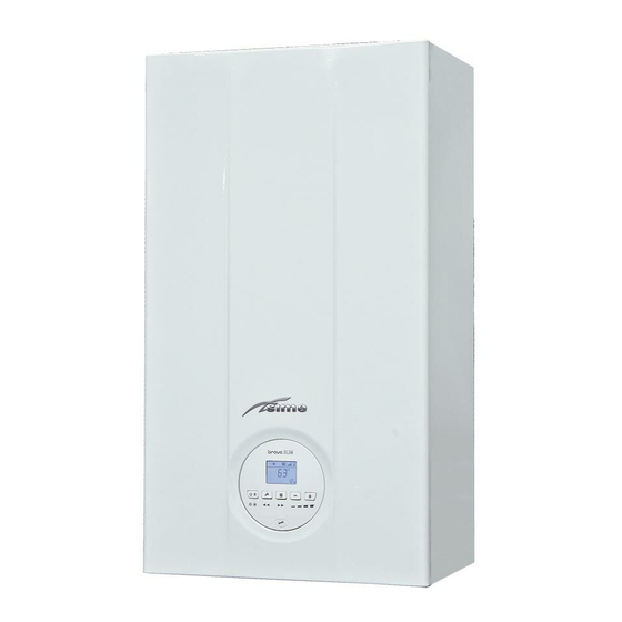
Condensing wall mounted boiler
BRAVA SLIM HE R
INSTALLATION AND SERVICING INSTRUCTIONS
EN
Gas Safety Certified AS/NZS 4552
LN: SAI-400196
CAUTION
This product must be installed exclusively by professionally qualified personnel in accordance with the requirements of
the standards AS/NZS 5601, AS/NZS 3500, AS/NZS 3000 (current version) of the local gas, electricity authorities and other
relevant legislation.
Fonderie SIME S.p.A.
6322891A - 05/2016 - R1
Advertisement
Chapters
Table of Contents

Related Manuals for Sime BRAVA SLIM HE R Series


Summary of Contents for Sime BRAVA SLIM HE R Series
- Page 1 This product must be installed exclusively by professionally qualified personnel in accordance with the requirements of the standards AS/NZS 5601, AS/NZS 3500, AS/NZS 3000 (current version) of the local gas, electricity authorities and other relevant legislation. Fonderie SIME S.p.A. 6322891A - 05/2016 - R1...
- Page 2 – Do not use electrical devices or appliances such as Dealer who sold the appliance. switches, electrical appliances etc if you can smell – The appliance must be used as intended by Sime fuel. If this should happen: who is not responsible for any damage caused to - open the doors and windows to air the room;...
- Page 3 RANGE TABLE OF CONTENTS MODEL CODE Brava Slim HE 20 R i - (Natural gas) 8112265 USER INSTRUCTIONS Brava Slim HE 20 R e - (Natural gas) 8112266 Brava Slim HE 40 R i - (Natural gas) 8112267 TABLE OF CONTENTS Brava Slim HE 40 R e - (Natural gas) 8112268 DESCRIPTION OF THE APPLIANCE...
-
Page 5: Table Of Contents
USER INSTRUCTIONS TABLE OF CONTENTS USING THE BOILER BRAVA SLIM HE R MAINTENANCE Control panel ........6 Adjustments. -
Page 6: Using The Boiler Brava Slim He R
USING THE BOILER BRAVA SLIM HE R pressing any one of these buttons for more than 30 NOTE: Control panel seconds generates a fault on the display without preventing boiler operation. The warning disappears when normal conditions are restored. DISPLAY . -
Page 7: Preliminary Checks
Preliminary checks Commissioning of the Brava Slim HE R boiler must be carried out by professionally qualified personnel after which the boiler can operate automatically. It may however be necessary for the User to start the appliance autonomously without involving a technician: for example, after a holiday. -
Page 8: Fault / Malfunction Codes
– set the main system switch to "OFF" Fault / malfunction codes – close the gas valve. If a fault/malfunction is detected during boiler operation, the message “ALL” will appear on the display followed by the fault code (eg. “06” - no flame detected). If the message also appears, press and hold the button... -
Page 9: Maintenance
MAINTENANCE DISPOSAL Adjustments Disposal of the equipment (European Directive 2002/96/CE) For the appliance to operate correctly and efficiently it is Once it reaches the end of its operating life, the equipment recommended that the User calls upon the services of a MUST BE RECYCLED in line with current legislation. -
Page 10: Handover Instructions
HANDOVER INSTRUCTIONS N° Description When done Fill in all the details on this Boiler manual. Instruct the owner /users on the correct operation of the heating system, including how to turn the systems on and off, adjust the time and temperature settings. Instruct how to turn the heating system off in summer and on for winter. - Page 11 Service – 2 – Year 3 Date Service technician PIC Licence No. Name Service Company Contact phone number Work Completed Notes Service – 3 – Year 5 Date Service technician PIC Licence No. Name Service Company Contact phone number Work Completed Notes Service –...
- Page 12 Service – 5 – Year 9 Date Service technician PIC Licence No. Name Service Company Contact phone number Work Completed Notes Service – 7 – Year 11 Date Service technician PIC Licence No. Name Service Company Contact phone number Work Completed Notes Service –...
- Page 13 DESCRIPTION OF THE APPLIANCE TABLE OF CONTENTS Main water circuit ......18 DESCRIPTION OF THE APPLIANCE Sensors.
-
Page 14: Description Of The Appliance
Safety device may only be replaced by professional installation, protected against atmospheric agents. The main qualified personnel using Sime original spare parts. elements choices made by Sime for the Brava Slim HE R boilers are: – the total pre-mix microflame burner combined with a steel... -
Page 15: Structure
Structure 7.4.1 Brava Slim HE 20 R i Brava Slim HE 40 R i Heat exchanger bleed point System pump Heat exchanger Water pressure transducer Combustion chamber door Automatic bleed valve Oversleeve Air-gas mixer Flame viewing window Expansion vessel Ignition/detection electrode Air inlet pipe Heat safety thermostat Air-smoke chamber... -
Page 16: Brava Slim He 20 R E Brava Slim He 40 R E
7.4.2 Brava Slim HE 20 R e Brava Slim HE 40 R e Heat exchanger bleed point System pump Heat exchanger Water pressure transducer Combustion chamber door Automatic bleed valve Oversleeve Air-gas mixer Flame viewing window Expansion vessel Ignition/detection electrode Air inlet pipe Heat safety thermostat Air-smoke chamber... -
Page 17: Technical Features
Technical features Brava Slim HE R DESCRIPTION 20 R i 20 R e 40 R i 40 R e CERTIFICATIONS Country of intended installation Fuel NATURAL GAS / UNIVERSAL LPG SAI GLOBAL number SAI-400196 Class NO 5 (< 70 mg/kWh) HEATING PERFORMANCE HEAT INPUT Nominal... -
Page 18: Main Water Circuit
Main water circuit 0°C 1°C 2°C 3°C 4°C 5°C 6°C 7°C 8°C 9°C 0°C 27279 26135 25044 24004 23014 22069 21168 20309 19489 18706 10°C 17959 17245 16563 15912 15289 14694 14126 13582 13062 12565 20°C 12090 11634 11199 10781 10382 9999 9633... -
Page 19: Control Panel
pressing any one of these buttons for more than 30 NOTE: 7.10 Control panel seconds generates a fault on the display without preventing boiler operation. The warning disappears when normal conditions are restored. DISPLAY . The symbol for "Summer" mode is displayed. “SUMMER”... -
Page 20: Wiring Diagram
7.11 Wiring diagram BLACK BLUE BROWN SAUX BLACK 4 3 2 1 4 5 6 BROWN BLUE CN12 CN13 CN15 CN14 CN11 CD. 6302285 Line Auxiliary sensor SAUX Neutral Safety thermostat Fuse (3.15AT) Thermal fuse Ignition transformer Smoke flue gas probe System pump Pressure transducer Air thermostat... - Page 21 INSTALLATION AND SERVICING INSTRUCTIONS TABLE OF CONTENTS INSTALLATION 10 MAINTENANCE Receiving the product ......22 10.1 Adjustments.
-
Page 22: Installation
INSTALLATION CAUTION Brava Slim HE R Description The appliance must be installed by the Sime Technical 20 R i 20 R e 40 R i 40 R e Service only, or by a qualified professional. W (mm) D (mm) H (mm) -
Page 23: Appliance
Before removing an old heat generator from an existing system, APPROXIMATE MINIMUM DISTANCES it is recommended that the user: – puts a descaling additive into the water system ≥ 5 – allows the system to work with the generator active for a few days –... -
Page 24: Plumbing Connections
CAUTION 8.10 Condensate outlet/collection – The wall on which the appliance is to be hung must In order to collect the condensate, it is recommended that: be of adequate strength and capable of holding the – the appliance condensate outlets and the smoke outlet are weight of the appliance and associated components ducted and pipework. -
Page 25: Connecting The Flue
8.12 Connecting the flue 8.12.1 Flue Terminal Positions Door Fig. 23 Brava Slim HE R DESCRIPTION Min. Clearance (mm) Flue terminal Mechanical air inlet Gas meter Electricity meter of fuse box Shaded area indicates prohibited area Below eaves, balconies and other projections (Appliances over 50MJ/h) From the ground, above a balcony or other surface From a return wall or external corner From a gas meter... -
Page 26: Installation Of Coaxial Flues 60/100Mm - 80/125Mm
8.12.2 Installation of coaxial flues 60/100mm – 8.12.4 Coaxial duct (Ø 60/100mm and Ø 80/125mm) 80/125mm Code Coaxial flue kits that are supplied separately. The diagrams Description Ø 60/100 mm Ø 80/125 mm below, illustrate some examples of fluing options allowed and Coaxial duct kit 8096250 8096253... -
Page 27: Brava Slim He 20 R E - 40 R E
If this cable needs to be replaced, an original spare must be requested from Sime . Therefore only the connections of the original components as shown in the table are needed. These are to be ordered separately from the boiler. -
Page 28: External Sensor
– remove the screws (3) securing the control panel (4) CAUTION – move the panel (4) upwards (a) but keeping it in the side It is compulsory: guides (5) to the end of travel – to use an omnipolar cut-off switch, disconnect –... -
Page 29: Chrono-Thermostat Or Air Thermostat
8.13.2 Chrono-thermostat or Air Thermostat MULTI ZONE system - with zone valve, air thermostat and external sensor. The electrical connection of the chrono-thermostat or air thermostat has already been described. When fitting the component in the room where the readings are to be taken, follow the instructions provided with the device. -
Page 30: Refilling Or Emptying
8.14 Refilling or emptying Before carrying out the operations described below, make sure that the main system switch is set to "ON" in order for the display to show the pressure level in the system during refilling. if this is not Make sure that the operating mode is set to "Stand-by";... -
Page 31: Commissioning
COMMISSIONING Preliminary operations Before commissioning the appliance, check that: – the type of gas is correct for the appliance – the gas isolation valves for the heating system and the water system are open – the pump impeller rotates freely –... -
Page 32: Parameter Setting And Display
– once the required parameter has been reached, press the Parameter setting and display to modify the value within the permitted range. buttons > < To go into the parameter menu: The modifications are stored automatically. – from the selected mode (eg. WINTER) When all the parameter modifications have been made, exit the –... -
Page 33: Fault / Malfunction Codes
Type Description Range Step Default External relay 2 function 0 = not used; 1 = remote alarm NO; 2 = remote alarm NC; 3 = zone valve; 4 = automatic filling; 5 = external request; 6 = recirculation 0 .. 9 pump;... -
Page 34: Display Of Operating Data And Counters
Type Description Fault on the valve control logic line/valve cable damaged Block due combustion during start-up Block due to numerous combustion control failures Irregular combustion (temporary error) Flow rate reduced for (presumed) low pressure on mains gas Internal error (board component protection) Unstable combustion feedback signal error –... -
Page 35: Checks After Commissioning
TABLE OF ACTIVATED ALARMS/FAULTS – close the gas valve – loosen the screw of the "mains pressure" point (6) and connect Type Description a pressure gauge Last activated alarm/fault Last but one activated alarm/fault Third from last activated alarm/fault Previous activated alarm/fault Previous activated alarm/fault Previous activated alarm/fault Previous activated alarm/fault... -
Page 36: Gas Conversion
– take the combustion data reading Gas conversion to exit the "Chimney sweeper – press the button models can work with NATURAL GAS or Brava Slim HE R Procedure”. The boiler water delivery temperature will UNIVERSAL LPG without the need for any mechanical appear on the display conversion. -
Page 37: Maintenance
10 MAINTENANCE 10.1 Adjustments 10.3 Cleaning the inside of the appliance For the appliance to operate correctly and efficiently it is 10.3.1 Removing components recommended that the User calls upon the services of a Professionally Qualified Technician to carry out ANNUAL To access the internal parts of the boiler: maintenance. -
Page 38: Cleaning The Burner And The Combustion Chamber
– loosen the clips (6) and extract the air inlet pipe (7) CAUTION – unscrew the swivel joint (8) Work carefully when removing the assembly (13) to – extract the connectors (9) from the fan and disconnect the prevent any damage occurring to the internal insulation electrode cable (10) of the combustion chamber and the door seal. -
Page 39: Unscheduled Maintenance
10.5 Unscheduled maintenance Type Fault Solution - Check the rotation of the If replacing the electronic board , the user MUST set the pump rotor parameters as indicated in the table. No water circulating - Check the electrical in the system Setting for connections Brava Slim HE R... - Page 40 Type Fault Solution Internal error - Contact the Technical (board component Assistance Centre protection) Unstable combustion - Contact the Technical feedback signal error Assistance Centre Combustion set - Contact the Technical cannot be reached Assistance Centre error System has reached maximum air - Contact the Technical correction error (at...
-
Page 41: Commissioning Boiler Checklist
11 COMMISSIONING BOILER CHECKLIST A suggested method of commissioning the boiler; the actual method can vary according to the boiler make, type and installation. The boiler must always be installed and commissioned by an approved gas technician. The installer certifies that this Boiler has been installed to the manufacturer's instructions, has been filled, commissioned and is ready for use. -
Page 42: Exploded Views
12 EXPLODED VIEWS - Brava Slim HE 40 R i Brava Slim HE 20 R i... - Page 43 - Brava Slim HE 40 R e Brava Slim HE 20 R e...
- Page 44 - Brava Slim HE 20 R e - Brava Slim HE 40 R i - Brava Slim HE 40 R e Brava Slim HE 20 R i...
- Page 45 - Brava Slim HE 20 R e - Brava Slim HE 40 R i - Brava Slim HE 40 R e Brava Slim HE 20 R i...
- Page 46 - Brava Slim HE 20 R e - Brava Slim HE 40 R i - Brava Slim HE 40 R e Brava Slim HE 20 R i...
- Page 47 BRAVA SLIM HE R BRAVA SLIM HE R Pos. Code Description Pos. Code Description 20 i 20 e 40 i 40 e 20 i 20 e 40 i 40 e 6264560 Boiler fixing bracket 6226636 D.H.W. elektrovalve fix.spring 6264565 Boiler fixing bracket 6227462 Flowing pipe to C.H.
-
Page 48: Removing Components
13 REMOVING COMPONENTS CAUTION 13.1.2 Side panels The maintenance interventions described must ONLY – Unscrew the screws (3) be carried out the professionally qualified personnel. – pull the side panel (4) outwards to release it from the top WARNING Before carrying out any interventions described: –... -
Page 49: Remove/Replace Sensor And Thermostat
13.3.2 Delivery sensor 13.3 Remove/replace sensor and thermostat – Remove front panel (see "Remove panels" on page 48) – disconnect the connectors (1) 13.3.1 Smoke flue gas probe – Remove front panel (see "Remove panels" on page 48) – disconnect the connector (1) Fig. -
Page 50: Heat Safety Thermostat
13.3.3 Heat safety thermostat 13.4 Remove electronic board – Remove front panel (see "Remove panels" on page 48) – Remove front panel (see "Remove panels" on page 48) – disconnect the connectors (1) – move the control panel (A) into a horizontal position (see " Rotate control panel"... -
Page 51: Remove/Replace Combustion Head Unit And Fan
– unscrew the screws (6) and unthread the combustion head (7) 13.5 Remove/replace combustion head unit and – unscrew the screws (8) and remove the fan (9) – Remove front panel (see "Remove panels" on page 48) – disconnect the fan connectors (1) –... -
Page 52: Remove/Replace The Ignition And Flame Detection
13.6 Remove/replace the ignition and flame 13.7 Remove/replace the siphon detection electrode – Remove front panel (see "Remove panels" on page 48) CAUTION – disconnect the connectors (1) and (2) When disassembling, some residual water may leak. – Remove the panelling (see "Remove panels" on page 48) –... -
Page 53: Remove/Replace Gas Valve
13.8 Remove/replace gas valve 13.9 Remove/replace the expansion vessel – Close the gas valve – Shut-off the valves to the system and empty the boiler – remove the front panel (see "Remove panels" on page 48) – remove the front panel (see "Remove panels" on page 48) –... -
Page 54: Remove/Replace System Pump
13.10 Remove/replace system pump – Shut-off the valves to the system and empty the boiler – remove the front panel (see "Remove panels" on page 48) – lift the connector (1) using a screwdriver (2) Fig. 78 – unscrew the swivel joints (3) and (4) –... - Page 56 Fonderie Sime S.p.A - Via Garbo, 27 - 37045 Legnago (Vr) Tel. +39 0442 631111 - Fax +39 0442 631292 - www.sime.it Fonderie SIME S.p.A.reserves the right to make changes at any time without prior notice in order to improve its products without compromising the essential characteristics.
Need help?
Do you have a question about the BRAVA SLIM HE R Series and is the answer not in the manual?
Questions and answers