Advertisement
Quick Links
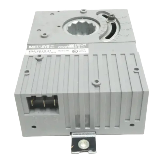
EDA-2040/ATP-2040 Electric Damper Actuator Installation
I
nstallation
The actuator is not position sensitive and can be
mounted in any convenient orientation. Wiring
terminals must be accessible and protected from
moisture and corrosive fumes. No extra mounting
brackets, linkage, or couplers are required for
standard mounting.
Note:
The standard length shaft coupler must be
used when the EDA-2040 or ATP-2040 is
used with an EDA-2040-102 Switch Kit.
K
it Includes
actuator
No. 10 thread cutting tapping screw
position scale
position indicator
CBL-2000 Wiring Harness (six female quick
connects with attached cables) for ATP-2040
Note:
The CBL-2000 can also be ordered
separately.
T
ools Required
screwdrivers, flat-blade (or nut driver) 5/16 in.
and No. 2 Phillips
Allen wrench (90 degree hex key), 1/8 and
9/64 in. short series
pliers
drill, 5/32 in. (4 mm) drill bit
screwdriver, No. 2 Phillips
continuity tester (visual, audio, or DVM)
!
CAUTION: Equipment Damage Hazard.
Disconnect all power supplies
before wiring and follow the
National Electrical Code and all
local regulations to avoid
© 1996 Johnson Controls, Inc.
Part No. 34-619-18, Rev. E
Code No. LIT-121342
FANs 121, 1628.3, 268.1
Technical Bulletin EDA-2040
Issue Date 0196
possible electrical shock or
damage to the equipment.
1
Advertisement

Subscribe to Our Youtube Channel
Related Manuals for Johnson Controls EDA-2040


Summary of Contents for Johnson Controls EDA-2040
- Page 1 No extra mounting brackets, linkage, or couplers are required for standard mounting. Note: The standard length shaft coupler must be used when the EDA-2040 or ATP-2040 is used with an EDA-2040-102 Switch Kit. it Includes actuator No. 10 thread cutting tapping screw...
- Page 2 CW mechanical limit. 6. If the damper shaft is longer than 2-1/4 inches, use the standard mounting procedures. If the damper shaft is shorter than 2-1/4 inches, use the flush mounting procedures. 2 EDA-2040/ATP-2040 Electric Damper Actuator Installation Technical Bulletin...
- Page 3 C B L-2000 C able H arness E D A -2 04 0 M o un ted for C onnection to V A V to V A V B ox C ontroller Figure 5: Actuator Position EDA-2040/ATP-2040 Electric Damper Actuator Installation Technical Bulletin 3...
- Page 4 Note: Maintain 1/8 in. clearance between the gear train and could reduce the mounting surface and the coupler while life of the actuator. tightening the hex set screws. 4 EDA-2040/ATP-2040 Electric Damper Actuator Installation Technical Bulletin...
- Page 5 1. Install the standard coupler onto the actuator as (cannot manually rotate a flush mounted instructed in the Mounting, Standard section. EDA-2040), and drive it to the full open and 2. Position the switch kit so that the switch kit closed positions to be sure of damper operation.
- Page 6 6. Insert the long arm of a hex key into the slots of DPT-2015 on an EDA-2040 Actuator the plastic coupler. Lift and hold the gear Check the EDA-2040 cover for two inside mounting release lever to rotate the coupler until the bosses as shown in Figure 14. If there are none,...
- Page 7 The pressure sensing probe provided with the VAV of the transmitter. box must be connected to the DPT-2015 using field 2. When used with a Johnson Controls VAV Series supplied 1/4 in. O.D. tubing as follows: controller, the DPT-2015 must be set up and 1.
- Page 8 0.4 and 0.6 volts, the transmitter is defective and should be replaced. 5. Verify that the damper is fully opening and closing. Note: If the transmitter is not mounted vertically, voltage readings may increase or decrease by 0.1 volts. 8 EDA-2040/ATP-2040 Electric Damper Actuator Installation Technical Bulletin...
- Page 9 Notes Controls Group 507 E. Michigan Street P.O. Box 423 Milwaukee, WI 53201 Printed in U.S.A. EDA-2040/ATP-2040 Electric Damper Actuator Installation Technical Bulletin 9...
Need help?
Do you have a question about the EDA-2040 and is the answer not in the manual?
Questions and answers