Table of Contents
Advertisement
Repair
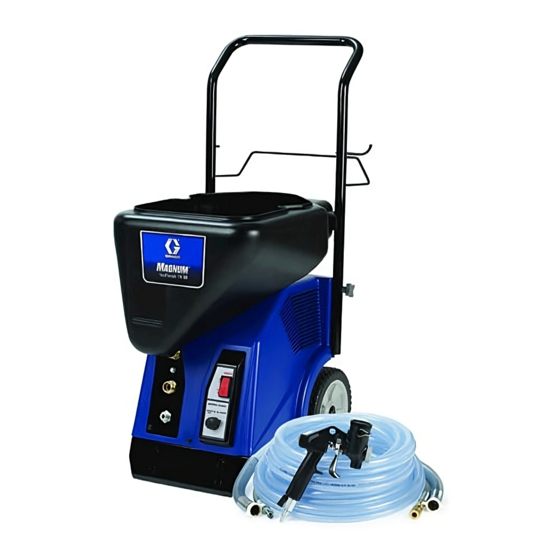
Interior Texture Sprayers
TX 90 & TX 125
Models: 254971 and 254972
70 psi (0.49 MPa, 4.9 bar)
Maximum Fluid Working Pressure
Important Safety Instructions
Read all warnings and instructions in this manual.
Save these instructions.
Related Manuals
311777
311764
Graco Inc. P.O. Box 1441 Minneapolis, MN 55440-1441
Copyright 2006, Graco Inc. is registered to I.S. EN ISO 9001
For Water-Based Materials Only
Model 254972 Shown
US
C
Conforms to ANSI/UL
standard 1450
311770B
ti8696a
Advertisement
Table of Contents

Related Manuals for Graco TX 90


Summary of Contents for Graco TX 90
- Page 1 Read all warnings and instructions in this manual. Save these instructions. Related Manuals 311777 311764 ti8696a Model 254972 Shown Graco Inc. P.O. Box 1441 Minneapolis, MN 55440-1441 Conforms to ANSI/UL Copyright 2006, Graco Inc. is registered to I.S. EN ISO 9001 standard 1450...
- Page 2 • Route hoses away from traffic areas, sharp edges, moving parts and hot surfaces. Do not expose Graco hoses to temperatures above 130 F (55 C) or below -35 F (-37 C). • Air hoses at the compressor end, can get very hot! Allow sprayer to cool down 15 minutes before removing air hose.
- Page 3 Warnings Warnings Electric Shock Hazard To reduce the risk of electric shock: • Be sure sprayer is adequately grounded through electrical outlet, page 6. • Use only 3-wire, extension cords. • Make sure ground prongs are intact on sprayer and extension cords. •...
- Page 4 Warnings CAUTION Water or material remaining in unit when temperatures are below freezing can damage motor and/or delay pump startup. To insure water and material are completely drained out of unit: 1. Remove material line from sprayer. ti8713a 2. Tip sprayer up as shown. Before adding material or starting unit in cold weather, run warm water through pump.
-
Page 5: Component Identification
Hopper Fitting (fluid inlet) Nozzle Material Hose Outlet Hose Plug Air Hose Outlet Material/Air Hose TX 90 - Hopper Gun/Spray Selector Switch Accessories Bag TX 125 - Hopper Gun Selector & Material Flow Control ON/OFF Switch Material Thickness Gauge Burp Guard... -
Page 6: Pressure Relief Procedure
Component Identification Pressure Relief Procedure Grounding and Electrical Requirements To reduce risk of injury, follow this procedure whenever you see this symbol throughout this This sprayer must be grounded. Grounding reduces the manual, Also, perform this procedure whenever risk of electrical shock by providing an escape wire for you: the electrical current. -
Page 7: Shroud Removal
Shroud Removal Shroud Removal Disassembly 6. Loosen screws (30) and (43) on shroud. 1. Relieve Pressure, page 6. 2. Unplug sprayer from outlet. ti9251a 7. Lift bottom front of shroud and pull up and over front ti2810b control to remove. 3. - Page 8 ™ RotoFlex II Pump ™ RotoFlex II Pump Disassemble Reassemble 1. Relieve Pressure, page 6. 1. Bend hose (16) so colored dots on hose fittings face each other. 2. Unplug sprayer from outlet. ti3084a 2. Slide new pump hose (16) over rollers. Move pump ti2810b rollers by hand until or flip power switch to rotate 3.
- Page 9 Compressor Compressor Use Compressor Repair Kit, 288612. 8. Remove 4 screws (29) and lift bracket (21) off of compressor. Disassembly 1. Relieve Pressure, page 6. 2. Unplug sprayer from outlet. ti9440a 9. Remove shoulder bolt (35) holding pump roller in ti2810b place.
- Page 10 Compressor Reassembly 6. Replace bracket (21) and tighten 4 screws (29). 1. Carefully position compressor back into sprayer body. Make sure piston head facing front of sprayer. ti9440a 7. Replace in. grounding screw (49) and tighten onto ti9443a ti9442a bracket (21). 2.
- Page 11 Piston/Cylinder Piston/Cylinder Use Piston/Cylinder Repair Kit 288609. 8. Use flat-blade screwdriver to pry head (74) from top of valve plate (75) and cylinder (76) from bottom of valve plate (75). Disassembly 9. Use 7/32 in. allen wrench to remove hex screw (87) 1.
- Page 12 Piston/Cylinder Reassembly 3. Replace three bolts (100) and use 1/2 in. socket to tighten into head (74). Torque all three bolts to 75 in-lb, then torque all bolts again to 210 in-lb. CAUTION Piston and cylinder come packaged 4. Replace muffler (110) as seen below and press onto together.
-
Page 13: Valve Plate
Valve Plate Valve Plate Use Valve Plate Repair Kit 288610. 8. Use flat-blade screwdriver to pry head (74) from top of valve plate (75) and cylinder (76) from bottom of valve plate (75). Disassembly 1. Relieve Pressure, page 6. Reassembly 2. - Page 14 Motor Motor Use Motor Repair Kit 288613. 8. Use a box end wrench to loosen and remove two mounting bolts (105) on motor (71). Disassembly 1. Relieve Pressure, page 6. 2. Unplug sprayer from outlet. ti8891a CAUTION Be careful not to bend or damage the cooling tube when removing it from the motor.
- Page 15 Motor Reassembly 5. Place compressor back into vice and torque bolts as described in steps 2 and 3. 1. Angle motor pulley through compressor belt (84) 6. Replace fan (72) and tighten set screw. and pull motor (71) into position. ti8892a ti8890a 7.
-
Page 16: Cooling Tube
Cooling Tube Cooling Tube Use Cooler Repair Kit 288614. 6. Use 3/8 in. socket to remove screw (101) and washer (102) under cooling tube (79). The cooling tube is extremely hot and can cause serious burns. Allow unit to completely cool before servicing the cooling tube. - Page 17 Cooling Tube Reassembly 3. Rotate cooling tube around and insert free end into push-to-connect fitting. Make sure tube is fully inserted. 1. Insert new cooling tube fitting and use 5/8 in. wrench to tighten. ti8942a 2. Insert cooling tube (79) and push into new fitting ti9014a (86).
- Page 18 Idler Idler Reassembly Use Idler Repair Kit 288611. 1. Install new compressor belt, page 14. Disassembly 2. Replace new Idler (108) and tighten screw (109). 1. Relieve Pressure, page 6. 3. Replace fan (72) and tighten set screw. 2. Unplug sprayer from outlet. 4.
- Page 19 Roller Pulley/Belt Roller Pulley/Belt Reassembly Use Roller Pulley Repair Kit 288616. 1. Install new compressor belt (83). Disassembly 2. Loop belt over roller pulley and align roller with bolt 1. Relieve Pressure, page 6. hole. 2. Unplug sprayer from outlet. 3.
- Page 20 Selector Switch Knob (TX 95) Selector Switch Knob (TX 95) Assembly Use Knob Repair Kit 288756. 1. Position new knob to point right (approximately 45° Disassembly from vertical) and slide it onto exposed spline. 1. Turn selector switch knob clockwise as far as it will ti9524a 2.
- Page 21 Selector Switch Knob (TX 125) Selector Switch Knob (TX 125) Assembly Use Knob Repair Kit 288768. 1. Position new knob to point down and slide it onto Disassembly exposed spline. 1. Turn selector switch knob clockwise until it points down. ti9435a 2.
-
Page 22: Regulator Valve
Regulator Valve Regulator Valve Assembly Use Regulator Repair Kit 288757 (TX 95). Use Regulator Repair Kit 288824 (TX 125). 1. Replace new regulator valve and feed through 3 holes on side of sprayer. Disassembly 1. Remove Knob, page 20. 2. Remove Shroud, page 7. 3. -
Page 23: Troubleshooting
Refer to Grounding and Electrical Requirements, page 6. Gun needle plugged Clean needle and retry. Worn compressor Replace compressor. Contact a qualified Graco Service Center. Lines not connected Check all quick disconnect connections to gun and hoses. Damaged hose Replace hose. - Page 24 Troubleshooting Problem Cause Solution Speed of application slow or slower Material too thick Thin material. Nozzle too small Change nozzles to a larger size. See Operation manual 311768. Too much air being used. Partially close gun air valve to reduce air flow.
-
Page 25: Wiring Diagram
Wiring Diagram Wiring Diagram Green Wire (GND) White Wire Power Cord Motor Black Wire Switch ti8937a Air Diagram Cylinder Air Valve Relief Valve Manifold on Compressor ti9232a Compressor Air Outlet... - Page 26 Parts Parts Models 254971 and 254972 ti8804a...
- Page 27 Parts Parts Models 254971 and 254972 ti8805a...
- Page 28 15K326 LABEL, hopper magnum TX 90 117633 SCREW, slot hex wash hd 15K330 LABEL, control magnum TX 90 15K289 BOLT, cord hanger 15K336 LABEL, side left magnum TX 90 15K284 HANGER, cord 15K337 LABEL, side right magnum TX 90 287953 COMPRESSOR, pump...
- Page 29 Parts Parts Models 254972 Part Description Qty. Part Description Qty. 113318 FITTING, elbow, plug in 288387 FRAME 111630 SCREW, mach, pnh 15H607 FRAME, bottom, right 276906 HOPPER, texture, .75 gal 15H606 FRAME, bottom, left 253897 GUN, spray, texture, w/hopper 288390 FRAME, back, texfinish, black 287967 PIN, gun clip 15J665 PANEL, control, texfinish, black 234188 CLAMP...
- Page 30 Part Description Qty. 288614 KIT, repair, cooler 288856 KIT, repair, compressor, complete; (includes 79, 86) TX 90 (includes all items) 120234 BELT 288651 KIT, repair, compressor; TX 125 120233 BELT (complete; includes all items) 120245 FITTING 288612 KIT, repair, compressor, rebuild...
-
Page 31: Technical Data
Model 254971: 8 gallons Model 254972: 10 gallons Gun material hopper: 3/4 gallon Maximum delivery with texture TX 90 - 0.9 gpm (3.4 lpm) TX 125 - 1.25 gpm (4.7 lpm) Dimensions: TX 90 Length 23 in. (584 mm) with handle Width 15.5 in. -
Page 32: Graco Standard Warranty
With the exception of any special, extended, or limited warranty published by Graco, Graco will, for a period of twelve months from the date of sale, repair or replace any part of the equipment determined by Graco to be defective.
Need help?
Do you have a question about the TX 90 and is the answer not in the manual?
Questions and answers