Table of Contents
Advertisement
Quick Links
FCI-...X-H114...
DE
Kurzbetriebsanleitung
FCI-...X-H114...
Weitere Unterlagen
Ergänzend zu diesem Dokument finden Sie im Internet unter
www.turck.com
Unterlagen:
■
Datenblatt
■
Konformitätserklärungen
Zu Ihrer Sicherheit
Bestimmungsgemäße Verwendung
Die Inline-Strömungssensoren mit integrierter Auswerteelektronik dienen zur Durchflussüber-
wachung von Wasser, Ölen, Alkoholen, Lacken sowie nicht explosiven Flüssigkeiten und Gasen.
Die Geräte sind zur Inline-Montage in einer Rohrleitung vorgesehen. Aufgrund des kalorimetri-
schen Funktionsprinzips sind die Geräte verschleißfrei.
Die Geräte dürfen nur wie in dieser Anleitung beschrieben verwendet werden. Jede andere
Verwendung gilt als nicht bestimmungsgemäß. Für daraus resultierende Schäden übernimmt
Turck keine Haftung.
Naheliegende Fehlanwendung
Die Geräte sind keine Sicherheitsbauteile und dürfen nicht zum Personen- oder Sachschutz
eingesetzt werden.
Allgemeine Sicherheitshinweise
■
Nur fachlich geschultes Personal darf das Gerät montieren, installieren, betreiben, paramet-
rieren und instand halten.
■
Das Gerät erfüllt die EMV-Anforderungen für den industriellen Bereich. Bei Einsatz in Wohn-
bereichen Maßnahmen treffen, um Funkstörungen zu vermeiden.
Produktbeschreibung
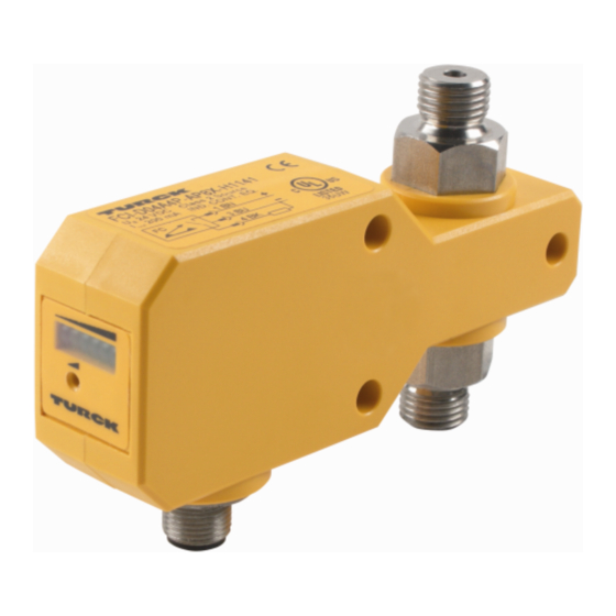
Geräteübersicht
Siehe Abb. 1: Produktbild (Beispiel), Abb. 2: Position der Potenziometer.
Funktionen und Betriebsarten
Die Ausgangsart, Erfassungsfunktionen und Anzahl der Potenziometer der Inline-Strömungs-
sensoren entnehmen Sie der folgenden Tabelle:
Typ
Ausgangsart
erfasste Prozesswerte
Potenziometer
FCI-...-LIX-...
Analogausgang,
Strömungszustand, Soll-
1 oder 2
4...20 mA
wertzustand, Anwesenheit
des Mediums, Strömungs-
geschwindigkeit
FCI-...-AP8X-...
Schaltausgang,
Strömungszustand, Soll-
1
PNP, Schließer
wertzustand, Anwesenheit
des Mediums
FCI-...-ARX-...
Relaisausgang,
Schließer
Die Werte für den Strömungszustand werden über die LEDs angezeigt.
Montieren
ACHTUNG
Scherkräfte zwischen den Rohranschlüssen des Geräts
Geräteschäden durch Scherkräfte
Geräte so montieren, dass keine Scherkräfte zwischen den Rohranschlüssen des Geräts
➤
auftreten (siehe Abb. 3).
Die Geräte sind zur Inline-Montage in einer Rohrleitung vorgesehen. Dazu kann die Rohrlei-
tung entweder direkt über die Schneidringverschraubung oder mit einem Adapterstück (nicht
im Lieferumfang enthalten) angeschlossen werden.
Bei vertikaler Montage: Durchflussrichtung beachten (siehe Abb. 4).
➤
Geräte unter Berücksichtigung des Gewindes und der Schlüsselweite montieren (siehe
➤
„Technical data").
Anschließen
Gerät gemäß „Wiring diagrams" anschließen.
➤
In Betrieb nehmen
Nach Anschluss der Leitungen und Aufschalten der Versorgungsspannung geht das Gerät auto-
matisch in Betrieb.
Betreiben
LEDs
Die Geräte mit Analogausgang verfügen über fünf grüne LEDs und eine rote LED.
Die Geräte mit Schalt- oder Relaisausgang verfügen über vier grüne LEDs, eine gelbe und eine
rote LED.
Geräteausführung LED
Bedeutung
FCI-...-LIX-...
grün
4...20 mA, Anzeige der Strömungsgeschwindigkeit
proportional zum Anzeigebereich
rot
4 mA unterschritten
FCI-...-A...X-...
grün und gelb eingestellter Sollwert überschritten, Ausgang geschaltet
gelb
eingesteller Sollwert erreicht, Ausgang geschaltet
rot
Strömung ausgefallen, vorgegebener Sollwert unter-
schritten, Ausgang nicht geschaltet
FR
Guide d'utilisation rapide
FCI-...X-H114...
Documents supplémentaires
folgende
Vous trouverez les documents suivants contenant des informations complémentaires à la
présente notice sur notre site Web www.turck.com :
■
Fiche technique
■
Déclarations de conformité
Pour votre sécurité
Utilisation conforme
Les capteurs de débit en ligne avec électronique de traitement intégrée sont utilisés pour la
surveillance du débit d'eau, d'huiles, d'alcools, de peintures ainsi que de liquides et de gaz non
explosifs.
Les appareils sont conçus pour être montés en ligne dans une tuyauterie. En raison du principe
de fonctionnement calorimétrique, les appareils sont sans usure.
Les appareils doivent exclusivement être utilisés conformément aux indications figurant dans
la présente notice. Toute autre utilisation est considérée comme non conforme. La société Turck
décline toute responsabilité en cas de dommages causés par une utilisation non conforme.
Mauvaises utilisations prévisibles
Les appareils ne constituent pas des composants de sécurité et ne peuvent pas être utilisés à
des fins de protection des personnes ou des choses.
Consignes de sécurité générales
■
Seul un personnel qualifié est habilité à monter, installer, faire fonctionner, paramétrer et
effectuer la maintenance de l'appareil.
■
L'appareil répond aux exigences CEM pour le domaine industriel. Lorsqu'il est utilisé dans
des zones résidentielles, prenez des mesures pour éviter les interférences radio.
Description du produit
Aperçu de l'appareil
Voir fig. 1 : Image du produit (exemple), fig. 2 : Position des potentiomètres.
Fonctions et modes de fonctionnement
Le type de sortie, les fonctions de détection et le nombre de potentiomètres des capteurs de
débit en ligne sont indiqués dans le tableau suivant :
Valeurs de processus
Type
Type de sortie
détectées
FCI-...-LIX-...
Sortie analo-
Etat du débit, état de
gique, 4...20 mA
la valeur de consigne,
présence du milieu, vitesse
du débit
FCI-...-AP8X-...
Sortie de commu-
Etat du débit, état de la
tation, PNP, N.O.
valeur de consigne,
présence du milieu
FCI-...-ARX-...
Sortie de relais,
N.O.
Les valeurs de l'état du débit sont affichées via des LED.
Installation
ATTENTION
Force de cisaillement entre les raccords de tuyauterie de l'appareil
Endommagement des appareils en cas de forces de cisaillement
Installez l'appareil de façon à ce qu'aucune force de cisaillement ne se produise entre les
➤
raccordements tubulaires de l'appareil (voir fig. 3).
Les appareils sont conçus pour être montés en ligne dans une tuyauterie. A cet effet, le tuyau
peut être raccordé directement à l'aide d'un raccord à bague coupante ou d'un adaptateur
(non fourni).
Pour un montage vertical : tenir compte du sens du débit (voir fig. 4).
➤
Installez les appareils en tenant compte du filetage et de la largeur de la clé (voir « Technical
➤
data »).
Raccordement
Raccordez l'appareil conformément aux schémas de câblage (« Wiring diagrams »).
➤
Mise en service
L'appareil se met automatiquement en marche après le raccordement des câbles et l'activation
de la tension d'alimentation.
Fonctionnement
LED
Les appareils à sortie analogique sont équipés de cinq LED vertes et d'une LED rouge.
Les appareils à sortie de commutation ou de relais sont équipés de quatre LED vertes, d'une
LED jaune et d'une LED rouge.
Version de
LED
Signification
l'appareil
FCI-...-LIX-...
Vert
4...20 mA, affichage de la vitesse du débit proportionnel
à la plage d'affichage
Rouge
Inférieur à 4 mA
FCI-...-A...X-...
Vert et jaune
Valeur de consigne réglée dépassée, sortie commutée
Jaune
Valeur de consigne réglée atteinte, sortie commutée
Rouge
Le débit est tombé, valeur de consigne définie non
atteinte, sortie non commutée
EN
Quick Start Guide
FCI-...X-H114...
Other documents
Besides this document the following material can be found on the Internet at www.turck.com:
■
Data sheet
■
Declarations of conformity
For your safety
Intended use
The inline flow sensors with an integrated evaluation electronics unit are used for monitoring
the flow of water, oils, alcohols, paints and non-explosive liquids and gases.
The devices are intended for inline mounting in a pipe. Due to the calorimetric operating
principle, the devices are wear-free.
The devices must only be used as described in these instructions. Any other use is not in ac-
cordance with the intended use. Turck accepts no liability for any resulting damage.
Obvious misuse
The devices are not safety components and must not be used for the protection of persons or
property.
General safety instructions
■
The device must only be fitted, installed, operated, parameterized and maintained by
trained and qualified personnel.
■
The device meets the EMC requirements for industrial areas. When used in residential areas,
take measures to prevent spark faults.
Product description
Device overview
See fig. 1: product image (example), fig. 2: position of the potentiometers.
Functions and operating modes
The output type of the inline flow sensors, as well as the detection functions and the number of
potentiometers that they are equipped with, can be found in the following table:
Type
Output type
Recorded process values
FCI-...-LIX-...
Analog output,
Flow status, setpoint status,
4...20 mA
presence of the medium,
flow rate
Potentiomètre
FCI-...-AP8X-...
Switching output,
Flow status, setpoint status,
PNP, NO contact
presence of the medium
1 ou 2
FCI-...-ARX-...
Relay output, NO
contact
The values for the flow status are displayed via the LEDs.
1
Installing
NOTICE
Shearing forces between the pipe connections of the device
Damage to equipment caused by shearing forces
Install the devices in such a way that shearing forces between the pipe connections of
➤
the device are prevented (see fig. 3).
The devices are intended for inline mounting in a pipe. When installing, the pipe can be con-
nected either directly via the cutting ring fitting or by using an adapter (not included in the
delivery).
For vertical mounting: observe the flow direction (see fig. 4).
➤
Mount the devices taking into account the thread and wrench size (see "Technical data").
➤
Connection
Connect the device as shown in "Wiring diagrams. "
➤
Commissioning
The device is operational automatically once the cables are connected and the power supply is
switched on.
Operation
LEDs
The devices with an analog output have five green LEDs and one red LED.
The devices with a switching or relay output have four green LEDs, one yellow LED and one red
LED.
Design
LEDs
Meaning
FCI-...-LIX-...
Green
4...20 mA, flow rate display proportional to the display
range
Red
4 mA undershot
FCI-...-A...X-...
Green and
Configured setpoint exceeded, output switched
yellow
Yellow
Configured setpoint reached, output switched
Red
Flow interrupted, specified setpoint undershot, output
not switched
2
LED
Pot. 2
Pot. 1
3
Potentiometers
1 or 2
1
Wiring diagrams
FCI...AP8X...
2 WH
FC
3 BU
1 BN
4 BK
FCI...LIX...
2 WH
3 BU
1 BN
4 BK
FCI...ARX...
2 WH
3 BU
1 BN
4 BK
© Hans Turck GmbH & Co. KG | D101293 2022-06
FCI-...X-H114...
Flow Sensors
Quick Start Guide
Doc. no. D101293 2206
Additional
information see
turck.com
4
flow
1 BN
+
3 BU
–
4 BK
1 BN
+
–
FC
3 BU
4 BK
1 BN
+
3 BU
–
FC
4 BK
2 WH
Advertisement
Table of Contents

Related Manuals for turck FCI-X-H114 Series


Summary of Contents for turck FCI-X-H114 Series
- Page 1 Ergänzend zu diesem Dokument finden Sie im Internet unter www.turck.com folgende Vous trouverez les documents suivants contenant des informations complémentaires à la Besides this document the following material can be found on the Internet at www.turck.com: ■ présente notice sur notre site Web www.turck.com : Unterlagen: Data sheet ■...
- Page 2 0.6…6 l/min Hans Turck GmbH & Co. KG | Witzlebenstraße 7, 45472 Mülheim an der Ruhr, Germany | Tel. +49 208 4952-0 | Fax +49 208 4952-264 | more@turck.com | www.turck.com © Hans Turck GmbH & Co. KG | D101293 2022-06...
- Page 3 사용 목적을 따르지 않는 것입니다. 터크는 그로 인한 손상에 대해 어떠한 책임도 지지 않습니다. Los dispositivos solo se deben usar como se describe en estas instrucciones. Ninguna otra 明显的误用 forma de uso corresponde al uso previsto. Turck no se responsabiliza de los daños derivados de 该装置不是安全部件, 不得用于个人防护或财产保护。 명백하게 부적절한 사용...
- Page 4 0.6…6 l/min Hans Turck GmbH & Co. KG | Witzlebenstraße 7, 45472 Mülheim an der Ruhr, Germany | Tel. +49 208 4952-0 | Fax +49 208 4952-264 | more@turck.com | www.turck.com © Hans Turck GmbH & Co. KG | D101293 2022-06...
Need help?
Do you have a question about the FCI-X-H114 Series and is the answer not in the manual?
Questions and answers