Table of Contents
Advertisement
Quick Links
Advertisement
Table of Contents

Related Manuals for turck BL20-E-3EMM Series


Summary of Contents for turck BL20-E-3EMM Series
- Page 1 BL20-E-3EMM-… Energy Measurement Modules Instructions for Use...
-
Page 2: Table Of Contents
Energy measurement on a motor (3-wire delta connection)........ 29 6.6.5 Energy measurement on a machine (4-wire star connection, non-blondel compliant)...................... 30 V01.00 | 2024/03 | 2 Hans Turck GmbH & Co. KG | T +49 208 4952-0 | more@turck.com | www.turck.com... - Page 3 General technical data .................... 64 14.2 BL20-E-3EMM-CT...................... 65 14.3 BL20-E-3EMM-RC ...................... 66 15 Turck branches — contact data .................... 67 V01.00 | 2024/03 | 3 Hans Turck GmbH & Co. KG | T +49 208 4952-0 | more@turck.com | www.turck.com...
-
Page 4: About These Instructions
If you have any suggestions for improving the design or if some information is missing in the document, please send your suggestions to techdoc@turck.com. V01.00 | 2024/03 | 4 Hans Turck GmbH & Co. KG | T +49 208 4952-0 | more@turck.com | www.turck.com... -
Page 5: Notes On The Product
The delivery consists of the following: Energy measurement module Quick Start Guide Turck service Turck supports you in your projects – from the initial analysis right through to the commission- ing of your application. The Turck product database at www.turck.com offers you several soft- ware tools for programming, configuring or commissioning, as well as data sheets and CAD files in many export formats. -
Page 6: For Your Safety
The product is designed according to state of the art technology. Residual hazards, however, still exist. Observe the following safety instructions and warnings in order to prevent danger to persons and property. Turck accepts no liability for damage caused by failure to observe these safety instructions. -
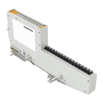
Page 7: Product Description
Reactive, apparent and active energy Power factor Frequency Phase angle Total Harmonic Distortion (THD) Device overview 75.5 74.6 160.8 Fig. 1: Dimensions BL20-E-3EMM V01.00 | 2024/03 | 7 Hans Turck GmbH & Co. KG | T +49 208 4952-0 | more@turck.com | www.turck.com... - Page 8 Not connected Current measurement, Rogowski coil Voltage measurement Neutral conductor n. c. Not connected Current measurement, Rogowski coil V01.00 | 2024/03 | 8 Hans Turck GmbH & Co. KG | T +49 208 4952-0 | more@turck.com | www.turck.com...
-
Page 9: Block Diagram
Filter I μC Module Filter U n.c. Filter I Filter U n.c. Filter I n.c. Filter I Fig. 3: Block diagram BL20-E-3EMM-RC V01.00 | 2024/03 | 9 Hans Turck GmbH & Co. KG | T +49 208 4952-0 | more@turck.com | www.turck.com... -
Page 10: Display Elements
The results of the measurements are made available in the process data of the module via a register interface. V01.00 | 2024/03 | 10 Hans Turck GmbH & Co. KG | T +49 208 4952-0 | more@turck.com | www.turck.com... -
Page 11: Functions And Operating Modes
Active power fundamental L1, L2, L3 Reactive power fundamental L1, L2, L3 Apparent power fundamental L1, L2, L3 Power factor L1, L2, L3 V01.00 | 2024/03 | 11 Hans Turck GmbH & Co. KG | T +49 208 4952-0 | more@turck.com | www.turck.com... -
Page 12: Frequency Measurement
[} 49]. V01.00 | 2024/03 | 12 Hans Turck GmbH & Co. KG | T +49 208 4952-0 | more@turck.com | www.turck.com... -
Page 13: Bl20 Accessories
6827070 Labels for electronic modules in slice design, 3 × DIN A5 sheet, slice, pre-perforated (laser printing), 3 × 19 labels V01.00 | 2024/03 | 13 Hans Turck GmbH & Co. KG | T +49 208 4952-0 | more@turck.com | www.turck.com... - Page 14 BL20-QV/4 6827107 4 grid BL20-QV/5 6827108 5 grid BL20-QV/6 6827109 6 grid BL20-QV/7 6827110 7 grid BL20-QV/8 6827111 8 grid V01.00 | 2024/03 | 14 Hans Turck GmbH & Co. KG | T +49 208 4952-0 | more@turck.com | www.turck.com...
-
Page 15: Mounting
Protect the installation site against heat radiation, rapid temperature fluctuations, dust, dirt, moisture and other environmental influences. V01.00 | 2024/03 | 15 Hans Turck GmbH & Co. KG | T +49 208 4952-0 | more@turck.com | www.turck.com... -
Page 16: Mounting Eco Modules
Press the ECO module against the DIN rail until the locking hook audibly engages. „ Push the ECO module to the left until the two lateral snap-in hooks on the left engage. V01.00 | 2024/03 | 16 Hans Turck GmbH & Co. KG | T +49 208 4952-0 | more@turck.com | www.turck.com... -
Page 17: Mounting End Bracket And End Plate
Insert the connectors of the end plate firmly into the recesses of the module. „ Screw the end bracket tight through the end plate. V01.00 | 2024/03 | 17 Hans Turck GmbH & Co. KG | T +49 208 4952-0 | more@turck.com | www.turck.com... -
Page 18: Connecting
BL20 gateway or from power feeding or bus refreshing modules. An additional voltage sup- ply for the module is not necessary. V01.00 | 2024/03 | 18 Hans Turck GmbH & Co. KG | T +49 208 4952-0 | more@turck.com | www.turck.com... -
Page 19: Voltage Measurement
+ (5A) + (5A) Fig. 6: Pin assignment BL20-E-3EMM-CT for Fig. 7: Pin assignment BL20-E-3EMM-RC for voltage measurement voltage measurement V01.00 | 2024/03 | 19 Hans Turck GmbH & Co. KG | T +49 208 4952-0 | more@turck.com | www.turck.com... -
Page 20: Current Measurement
Fig. 10: Terminal assignment BL20-E-3EMM-RC for current measurement with Rogowski coils V01.00 | 2024/03 | 20 Hans Turck GmbH & Co. KG | T +49 208 4952-0 | more@turck.com | www.turck.com... -
Page 21: Connecting Current Transformers To Bl20-E-3Emm-Ct
+ (1A) + (5A) + (1A) + (5A) + (1A) + (5A) + (1A) + (5A) Fig. 11: Terminal assignment BL20-E-3EMM-CT V01.00 | 2024/03 | 21 Hans Turck GmbH & Co. KG | T +49 208 4952-0 | more@turck.com | www.turck.com... -
Page 22: Maximum Length Of The Connection Cable For Current Transformers
Internal resistance of the energy measurement module Secondary current = 1 A 60 mΩ Secondary current = 5 A 10 mΩ V01.00 | 2024/03 | 22 Hans Turck GmbH & Co. KG | T +49 208 4952-0 | more@turck.com | www.turck.com... -
Page 23: Required Secondary Apparent Power Of The Current Transformer
Power loss of the module: Secondary current = 1 A: 60 mW Secondary current = 5 A: 250 mW V01.00 | 2024/03 | 23 Hans Turck GmbH & Co. KG | T +49 208 4952-0 | more@turck.com | www.turck.com... -
Page 24: Connecting Rogowski Coils To Bl20-E-3Emm-Rc
Connect the Rogowski coils to the energy measuring module according to the terminal assignment. n.c. n.c. n.c. n.c. n.c. n.c. n.c. n.c. Fig. 13: Terminal assignment BL20-E-3EMM-RC V01.00 | 2024/03 | 24 Hans Turck GmbH & Co. KG | T +49 208 4952-0 | more@turck.com | www.turck.com... -
Page 25: Application Examples
Fig. 14: Energy measurement in a 3-phase supply network (4WY) „ Optional: For current measurement at the neutral conductor, connect fourth current transformer between I and N. V01.00 | 2024/03 | 25 Hans Turck GmbH & Co. KG | T +49 208 4952-0 | more@turck.com | www.turck.com... -
Page 26: Energy Measurement In A 3-Phase Supply Network (4-Wire Delta Connection)
Fig. 15: Energy measurement in a 3-phase supply network (4WD) „ Optional: For current measurement at the neutral conductor, connect fourth current transformer between I and N. V01.00 | 2024/03 | 26 Hans Turck GmbH & Co. KG | T +49 208 4952-0 | more@turck.com | www.turck.com... -
Page 27: Energy Measurement On A Machine (4-Wire Star Connection, 3- And Single-Phase Measurement)
+ (5A) + (1A) + (5A) + (1A) + (5A) + (1A) + (5A) Fig. 16: Energy measurement on a machine (4WY) V01.00 | 2024/03 | 27 Hans Turck GmbH & Co. KG | T +49 208 4952-0 | more@turck.com | www.turck.com... - Page 28 Fig. 17: Single-phase energy measurement on a machine (M1P), example The single-phase measurement can be carried out on all three phases. Several parallel single- phase measurements are also possible. V01.00 | 2024/03 | 28 Hans Turck GmbH & Co. KG | T +49 208 4952-0 | more@turck.com | www.turck.com...
-
Page 29: Energy Measurement On A Motor (3-Wire Delta Connection)
+ (5A) + (1A) + (5A) + (1A) + (5A) + (1A) + (5A) Fig. 18: Energy measurement on a motor (3WD) V01.00 | 2024/03 | 29 Hans Turck GmbH & Co. KG | T +49 208 4952-0 | more@turck.com | www.turck.com... -
Page 30: Energy Measurement On A Machine (4-Wire Star Connection, Non-Blondel Compliant)
+ (1A) + (5A) + (1A) + (5A) + (1A) + (5A) Fig. 19: Energy measurement on a machine, non-blondel compliant( 4WYNB) V01.00 | 2024/03 | 30 Hans Turck GmbH & Co. KG | T +49 208 4952-0 | more@turck.com | www.turck.com... -
Page 31: Energy Measurement On A Motor (4-Wire Delta Connection, Non-Blondel Compliant)
To do this, the parameter IL2 calculation activ- ated has to be set to 1 = yes [} 34]. V01.00 | 2024/03 | 31 Hans Turck GmbH & Co. KG | T +49 208 4952-0 | more@turck.com | www.turck.com... -
Page 32: 2-Phase Energy Measurement In A 3-Phase Network
+ (1A) + (5A) + (1A) + (5A) + (1A) + (5A) Fig. 21: Energy measurement in a 2-phase supply network (3Wx) V01.00 | 2024/03 | 32 Hans Turck GmbH & Co. KG | T +49 208 4952-0 | more@turck.com | www.turck.com... -
Page 33: Commissioning
The energy measurement module is part of the BL20 system and can only be commissioned in conjunction with a BL20 gateway. Commissioning of the BL20 gateways is described in the re- spective gateway operating instructions. V01.00 | 2024/03 | 33 Hans Turck GmbH & Co. KG | T +49 208 4952-0 | more@turck.com | www.turck.com... -
Page 34: Parameterizing And Configuring
Process value index ch 0 Process value index ch 1 … … Process value index ch 6 Process value index ch 7 V01.00 | 2024/03 | 34 Hans Turck GmbH & Co. KG | T +49 208 4952-0 | more@turck.com | www.turck.com... - Page 35 Current IL2 is measured. enabled 0x01 Current IL2 is calculated from the two currents IL1 and IL3: IL2 = -IL1 - IL3 V01.00 | 2024/03 | 35 Hans Turck GmbH & Co. KG | T +49 208 4952-0 | more@turck.com | www.turck.com...
- Page 36 L1, L2 or L3. 0x04 0b100 Basic nominal voltage L3 Line nominal 0… 0x00… Line nominal voltage in V voltage 255, 0xFF, 0xE6 V01.00 | 2024/03 | 36 Hans Turck GmbH & Co. KG | T +49 208 4952-0 | more@turck.com | www.turck.com...
- Page 37 Activates the voltage alarm (minimum limit Ln value) 0x04 0b00000100 Current upper Activates the current alarm (maximum limit Ln value) V01.00 | 2024/03 | 37 Hans Turck GmbH & Co. KG | T +49 208 4952-0 | more@turck.com | www.turck.com...
- Page 38 Process value index 32 bit process data Mapped by index specification in pro- ch 5 cess output data byte 20 and 23 V01.00 | 2024/03 | 38 Hans Turck GmbH & Co. KG | T +49 208 4952-0 | more@turck.com | www.turck.com...
-
Page 39: Parameterizing Limit Value Alarms
(parameter bytes 11…23). The exceeding or falling below of limit values is then output in the process input data (bytes 3…5) as a process alarm. V01.00 | 2024/03 | 39 Hans Turck GmbH & Co. KG | T +49 208 4952-0 | more@turck.com | www.turck.com... -
Page 40: Measured Value
No valid measurement if this is valid for all channels: Current input deactivated Undercurrent at current input V01.00 | 2024/03 | 40 Hans Turck GmbH & Co. KG | T +49 208 4952-0 | more@turck.com | www.turck.com... - Page 41 0x26 Reactive power L2 0x27 Reactive power L3 0x28 Apparent power L1 0x29 Apparent power L2 0x2A Apparent power L3 V01.00 | 2024/03 | 41 Hans Turck GmbH & Co. KG | T +49 208 4952-0 | more@turck.com | www.turck.com...
- Page 42 0x41 Line voltage L1 - L3 Undervoltage at voltage input 0x42 Line voltage L2 - L3 Parameter ”Connection type” = „3Wx” or „M1P” [} 34] V01.00 | 2024/03 | 42 Hans Turck GmbH & Co. KG | T +49 208 4952-0 | more@turck.com | www.turck.com...
- Page 43 0x8E Reactive energy fundamental accumulated L3 0x8F Apparent energy fundamental accumulated L1 Apparent energy fundamental accumulated L2 Apparent energy fundamental accumulated L3 V01.00 | 2024/03 | 43 Hans Turck GmbH & Co. KG | T +49 208 4952-0 | more@turck.com | www.turck.com...
- Page 44 Diagnosis No measured value, if necessary, the module diagnostics can be mapped into a 32-bit data channel via this index. V01.00 | 2024/03 | 44 Hans Turck GmbH & Co. KG | T +49 208 4952-0 | more@turck.com | www.turck.com...
-
Page 45: Measured Value Representation
0x1E Phase angle UL3 - IL3 0x1F Power factor L1 1 = 0x3FFF × (1/16383) 0x20 Power factor L2 0x21 Power factor L3 V01.00 | 2024/03 | 45 Hans Turck GmbH & Co. KG | T +49 208 4952-0 | more@turck.com | www.turck.com... - Page 46 0x36 Reactive power fundamental L3 0x37 Apparent power fundamental L1 0x38 Apparent power fundamental L1 0x39 Apparent power fundamental L1 V01.00 | 2024/03 | 46 Hans Turck GmbH & Co. KG | T +49 208 4952-0 | more@turck.com | www.turck.com...
- Page 47 ± 214748364.7 Varh × (1/10) fundamental accumulated L1 0x8D Reactive energy fundamental accumulated L2 0x8E Reactive energy fundamental accumulated L3 V01.00 | 2024/03 | 47 Hans Turck GmbH & Co. KG | T +49 208 4952-0 | more@turck.com | www.turck.com...
- Page 48 Peak value current Depending on the (2147483647 × × (resolution/1000) L1…L3 resolution: (resolution/1000) 0x01 = 0.1 mA, 1 mA, 10 mA, 100 mA, 1000 mA Diagnosis V01.00 | 2024/03 | 48 Hans Turck GmbH & Co. KG | T +49 208 4952-0 | more@turck.com | www.turck.com...
-
Page 49: Mapping Measured Values Into The Process Data Via The Register Interface
(bytes 24...31) for the respective data channel is set to 0 = enable dynamic interface or no measured value index has been selected. Fig. 22: Enable dynamic interface, example CODESYS V01.00 | 2024/03 | 49 Hans Turck GmbH & Co. KG | T +49 208 4952-0 | more@turck.com | www.turck.com... - Page 50 Value in Bit Data valid measurement Æ FALSE range? Output measured value and invert DYI Toggle bit Fig. 23: Dynamic interface V01.00 | 2024/03 | 50 Hans Turck GmbH & Co. KG | T +49 208 4952-0 | more@turck.com | www.turck.com...
- Page 51 : UINT; uiStep uiVoltage : UINT; uiCurrent : UINT; uifrequency : UINT;: END_VAR Fig. 24: CODESYS: Variable mapping in the example program V01.00 | 2024/03 | 51 Hans Turck GmbH & Co. KG | T +49 208 4952-0 | more@turck.com | www.turck.com...
- Page 52 := 0; // next step END_IF END_CASE // save DIY toggle bit ixDYIToggleOld := GVL_IO.ixDYIToggle; END_IF Fig. 25: CODESYS: example program V01.00 | 2024/03 | 52 Hans Turck GmbH & Co. KG | T +49 208 4952-0 | more@turck.com | www.turck.com...
-
Page 53: Operating
32 bit measured values (index 128…151, 255) must be mapped to 32-bit data channels ch4…ch7. V01.00 | 2024/03 | 53 Hans Turck GmbH & Co. KG | T +49 208 4952-0 | more@turck.com | www.turck.com... -
Page 54: Process Output Data
Process value ch 7 LLSB Process value ch 7 LSB Process value ch 7 MSB Process value ch 7 MMSB V01.00 | 2024/03 | 54 Hans Turck GmbH & Co. KG | T +49 208 4952-0 | more@turck.com | www.turck.com... - Page 55 Lower limit current underrun L… Upper limit frequency overrun Lower limit frequency underrun Lower limit power factor underrun 0 Upper current unbalance overrun 0 V01.00 | 2024/03 | 55 Hans Turck GmbH & Co. KG | T +49 208 4952-0 | more@turck.com | www.turck.com...
-
Page 56: Enable And Reset Accumulated 32-Bit Measured Values (Counter Values)
0 0 1 2 3 4 4 4 4 0 0 0 1 2 3 0 0 0 1 2 3 3 3 Fig. 26: Gate-reset function V01.00 | 2024/03 | 56 Hans Turck GmbH & Co. KG | T +49 208 4952-0 | more@turck.com | www.turck.com... -
Page 57: Led Displays
5-A-connection: < 100 mA or > 5.5 A BL20-E-3EMM-RC: output voltage of the Rogowski coil: < 10 mV or > 385 mV Channel inactive V01.00 | 2024/03 | 57 Hans Turck GmbH & Co. KG | T +49 208 4952-0 | more@turck.com | www.turck.com... - Page 58 Normal operation Phase Sequence Error Red flashing (0.5 Hz) Temperature in the device outside the permissible range Module inactive, no voltage supply V01.00 | 2024/03 | 58 Hans Turck GmbH & Co. KG | T +49 208 4952-0 | more@turck.com | www.turck.com...
-
Page 59: Status And Diagnostic Messages
Lower limit current underrun Upper limit frequency overrun Lower limit frequency underrun Lower limit power factor underrun Upper current unbalance overrun V01.00 | 2024/03 | 59 Hans Turck GmbH & Co. KG | T +49 208 4952-0 | more@turck.com | www.turck.com... -
Page 60: Hardware Device Diagnostics
(secondary side of the current transformer or Rogowski coil): BL20-E-3EMM-CT: 0.75 W (1 A connection) or 2.5 W (5 A connection) BL20-E-3EMM-RC: 0.25 W V01.00 | 2024/03 | 60 Hans Turck GmbH & Co. KG | T +49 208 4952-0 | more@turck.com | www.turck.com... - Page 61 BL20-E-3EMM-CT: > 1.1 A (1 A connection) or > 5.5 A (5 A connec- tion) BL20-E-3EMM-RC: Output voltage of the Rogowski coil > 385 V V01.00 | 2024/03 | 61 Hans Turck GmbH & Co. KG | T +49 208 4952-0 | more@turck.com | www.turck.com...
-
Page 62: Troubleshooting
1 is connected terminals to I current transformer at phase L2 is connected to terminals I , etc. V01.00 | 2024/03 | 62 Hans Turck GmbH & Co. KG | T +49 208 4952-0 | more@turck.com | www.turck.com... -
Page 63: Repair
Loosen the gateway from the DIN rail and remove it from the DIN rail. Disposal The devices must be disposed of properly and do not belong in the domestic waste. V01.00 | 2024/03 | 63 Hans Turck GmbH & Co. KG | T +49 208 4952-0 | more@turck.com | www.turck.com... -
Page 64: Technical Data
Flexible with ferrule without plastic sleeve 0.2…1.5 mm Flexible with ferrule with plastic sleeve 0.2…0.75 mm Wire cross section AWG 24…16 V01.00 | 2024/03 | 64 Hans Turck GmbH & Co. KG | T +49 208 4952-0 | more@turck.com | www.turck.com... -
Page 65: Bl20-E-3Emm-Ct
+ (5 A) , I + (1 A), I + (5 A) , I Current measurement (neutral conductor) +, I Voltage measurement V01.00 | 2024/03 | 65 Hans Turck GmbH & Co. KG | T +49 208 4952-0 | more@turck.com | www.turck.com... -
Page 66: Bl20-E-3Emm-Rc
150 ppm/K Connection terminals Current measurement (phase) +, RC +, RC +, RC Current measurement (neutral conductor) +, RC Voltage measurement V01.00 | 2024/03 | 66 Hans Turck GmbH & Co. KG | T +49 208 4952-0 | more@turck.com | www.turck.com... -
Page 67: Turck Branches - Contact Data
Via San Domenico 5, IT-20008 Bareggio (MI) www.turckbanner.it Japan TURCK Japan Corporation ISM Akihabara 1F, 1-24-2, Taito, Taito-ku, 110-0016 Tokyo www.turck.jp V01.00 | 2024/03 | 67 Hans Turck GmbH & Co. KG | T +49 208 4952-0 | more@turck.com | www.turck.com... - Page 68 United Kingdom TURCK BANNER LIMITED Blenheim House, Hurricane Way, GB-SS11 8YT Wickford, Essex www.turckbanner.co.uk Turck Inc. 3000 Campus Drive, USA-MN 55441 Minneapolis www.turck.us V01.00 | 2024/03 | 68 Hans Turck GmbH & Co. KG | T +49 208 4952-0 | more@turck.com | www.turck.com...
- Page 69 Over 30 subsidiaries and 60 representations worldwide! 100044850 | 2024/03 100044850 www.turck.com...
Need help?
Do you have a question about the BL20-E-3EMM Series and is the answer not in the manual?
Questions and answers