Advertisement
Quick Links
sauder.com
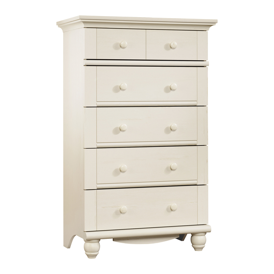
5-Drawer Chest
Harbor View Collection | Model 158015
Need help? Visit Sauder.com to view video assembly tips or chat with a live rep.
Prefer the phone? Call 1-800-523-3987.
Share your journey!
Don't get caught with
your pants on the
ground.
NOTE: THIS INSTRUCTION
BOOKLET CONTAINS IMPORTANT
SAFETY INFORMATION.
PLEASE READ AND KEEP FOR
FUTURE REFERENCE.
English pg 1-24
Français pg 25-28
Español pg 29-32
Lot # 388806
02/18/16
Purchased: __________________
Be sure to give us a ring before
making any returns. 1-800-523-3987
Advertisement

Subscribe to Our Youtube Channel
Related Manuals for Sauder Harbor View 158015


Summary of Contents for Sauder Harbor View 158015
- Page 1 Harbor View Collection | Model 158015 NOTE: THIS INSTRUCTION BOOKLET CONTAINS IMPORTANT SAFETY INFORMATION. Need help? Visit Sauder.com to view video assembly tips or chat with a live rep. PLEASE READ AND KEEP FOR FUTURE REFERENCE. Prefer the phone? Call 1-800-523-3987.
- Page 2 SMALL DRAWER LEFT SIDE (1) LARGE MIDDLE DRAWER FRONT (3) RIGHT MOLDING (1) LARGE DRAWER RIGHT SIDE (4) LARGE BOTTOM DRAWER FRONT (1) LEFT MOLDING (1) LARGE DRAWER LEFT SIDE (4) SMALL DRAWER FRONT (1) FOOT (2) Page 2 158015 www.sauder.com/services...
- Page 3 Now you know Part Identifi cation our ABCs. D170 D945 D171 D945 D171 D945 www.sauder.com/services 158015 Page 3...
- Page 4 Use of tip-over restraints may only reduce, but not eliminate, the risk of tip-over. This is a permanent label. Do not attempt to remove! 04/10 332296 (Refer to Step 18 for proper location and application) Page 4 158015 www.sauder.com/services...
- Page 5 BLACK 1-1/4" FLAT HEAD SCREW - 10 MM GOLD 5/16" FLAT HEAD SCREW - 40 BLACK 1-1/8" PAN HEAD SCREW - 4 BLACK 9/16" LARGE HEAD SCREW - 1 30S BLACK 1-9/16" FLAT HEAD SCREW - 25 www.sauder.com/services 158015 Page 5...
- Page 6 fl oor. Scan this QR code or go to this address: http://qr.sauder.com/?ID=1423 To begin assembly, push a SAUDER TWIST-LOCK® to watch a video on how to assemble your unit. å FASTENER (CC) into the large holes in the BRACES (D and E).
- Page 7 DRAWER BRACES (M67). Then, insert the metal end of a CAM DOWEL (2F) into each HIDDEN CAM. Do not tighten the HIDDEN CAMS in this step. Arrow (11 used) Arrow Insert the metal end of the CAM DOWEL into the HIDDEN CAM. www.sauder.com/services 158015 Page 7...
- Page 8 ENDS (A3 and B3). Use twenty GOLD 5/16" FLAT HEAD Remember: SCREWS (MM) through holes #1 and #3. Righty tighty. Lefty loosey. *patent pending glide system å GOLD 5/16" FLAT HEAD SCREW (20 used in this step) Glide end Finished edge Glide end Finished edge Page 8 158015 www.sauder.com/services...
- Page 9 Step 4 Fasten the UPPER BRACE (E) to the UPPER BRACE å ® How to use the SAUDER TWIST-LOCK FASTENER MOLDING (Q). Tighten three TWIST-LOCK® FASTENERS. 1. Insert the dowel end of the FASTENER into the hole of the adjoining part.
- Page 10 Step 5 Tap two MOLDING CONNECTORS (FF) into the notches å in the MOLDINGS (T, U, and V). Use your hammer to tap the MOLDING CONNECTORS (FF) into the notches in the MOLDINGS. Flat end Flat end Page 10 158015 www.sauder.com/services...
- Page 11 Step 6 Fasten the LEFT END (B3) to the LEFT MOLDING (V). Use å two BLACK 2-1/4" FLAT HEAD SCREWS (HH). BLACK 2-1/4" FLAT HEAD SCREW (2 used in this step) Finished edge www.sauder.com/services 158015 Page 11...
- Page 12 Tighten Risk of damage or Arrow injury. HIDDEN CAMS must be completely Arrow Maximum tightened. HIDDEN 210 degrees CAMS that are not completely tightened may loosen, and parts may separate. To Minimum completely tighten: 190 degrees Page 12 158015 www.sauder.com/services...
- Page 13 NOTE: You should start each SCREW a few turns before å completely tightening any of them. BLACK 1-7/8" FLAT HEAD SCREW Rounded edge (2 used in this step) Surface and edge with TWIST-LOCK® FASTENERS BLACK 1-1/8" PAN HEAD SCREW (4 used in this step) www.sauder.com/services 158015 Page 13...
- Page 14 NOTE: Do not put any pressure on the LOWER BRACES (D) å until they are fastened to the RIGHT END in the next step. Surface and edge with TWIST-LOCK® FASTENERS Surface and edge with TWIST-LOCK® FASTENERS Page 14 158015 www.sauder.com/services...
- Page 15 Tighten two TWIST-LOCK® FASTENERS. NOTE: Be sure the METAL PINS in the edges of the å LOWER BRACES insert into the holes in the RIGHT END. BLACK 2-1/4" FLAT HEAD SCREW (2 used in this step) Finished edge www.sauder.com/services 158015 Page 15...
- Page 16 NOTE: You should start each SCREW a few turns before å completely tightening any of them. Do not overtighten the SCREWS. Rounded edge BLACK 1-5/8" PAN HEAD SCREW (7 used in this step) r f a w i t o l e Page 16 158015 www.sauder.com/services...
- Page 17 Push the UPPER BRACE (E) onto the TWIST-LOCK® å FASTENERS in the ENDS (A3 and B3). Fasten the UPPER BRACE (E) to the ENDS (A3 and B3). å Tighten four TWIST-LOCK® FASTENERS. Push the UPPER BRACE (E) onto the TWIST-LOCK® FASTENERS. www.sauder.com/services 158015 Page 17...
- Page 18 Next, turn a FOOT (AA) onto the other end of each FOOT å SCREW (BB). Turn the FEET clockwise until the FOOT SCREWS are tight in the BOTTOM MOLDING and FEET. NOTE: Do not overtighten the FOOT SCREWS. å Page 18 158015 www.sauder.com/services...
- Page 19 Fasten the DRAWER BRACE (M67) to the SMALL å å DRAWER SIDES (D24 and D25) and DRAWER BRACE (M67). DRAWER FRONT (L2). Tighten one HIDDEN CAM. Use five BLACK 1-9/16" FLAT HEAD SCREWS (30S). Repeat this step for the LARGE DRAWERS. www.sauder.com/services 158015 Page 19...
- Page 20 (10 used for the KNOBS) Glide end Screw head - turn CAM to line up holes in the SLIDES with holes in DRAWER SIDES Glide end GOLD 5/16" FLAT HEAD SCREW (20 used in this step) Page 20 158015 www.sauder.com/services...
- Page 21 NOTE: Before moving your unit to a diff erent location, unscrew the SAFETY DRYWALL ANCHOR (61M) from your wall. å The nylon sheath will remain behind your wall. BLACK 9/16" LARGE HEAD SCREW (1 used in this step) www.sauder.com/services 158015 Page 21...
- Page 22 NOTE: Be sure the drawer with the LARGE BOTTOM å DRAWER FRONT (H2) is inserted at the bottom of the unit. Place the glide on the SLIDE behind the glide on the RAIL. Page 22 158015 www.sauder.com/services...
- Page 23 -Never open more than one drawer at a time. -If equipped with a drawer interlock system, do not defeat or remove it. Use of tip-over restraints may only reduce, but not eliminate, the risk of tip-over. 20 lbs. 20 lbs. 35 lbs. each www.sauder.com/services 158015 Page 23...
- Page 24 #2. The higher the screw in the oblong hole, the higher your drawer front will be. The lower the screw, the lower the drawer front. Page 24 158015 www.sauder.com/services...
- Page 25 EXTRÉMITÉ DROITE ..........1 35AD TIROIR GAUCHE ............5 pour future référence. EXTRÉMITÉ GAUCHE ..........1 EXCENTRIQUE ESCAMOTABLE ....11 Pour contacter Sauder DESSUS ................1 CHEVILLE D'EXCENTRIQUE ......11 en ce qui concerne cet élément, faire référence ENTRETOISE INFÉRIEURE ........2 13M RONDELLE ................1 au numéro de lot et...
- Page 26 éviter d'endommager l'élément ou le sol. ÉTAPE 6 Pour commencer l'assemblage, enfoncer une FIXATION TWIST-LOCK® SAUDER (CC) dans les gros trous des ENTRETOISES (D et E). Fixer l'EXTRÉMITÉ GAUCHE (B3) à la MOULURE GAUCHE (V). Insérer quatre GOUPILLES EN MÉTAL (GG) dans les petits trous Utiliser deux VIS TÊTE PLATE 57 mm NOIRES (HH).
- Page 27 4 Fixer l'ARRIÈRE DE PETIT TIROIR (D170) aux CÔTÉS DE PETIT TIROIR (D24 et D25) et à l’ENTRETOISE DE TIROIR (M67). Utiliser cinq VIS TÊTE PLATE 40 mm NOIRES (30S). Répéter cette étape pour les GRANDS TIROIRS. www.sauder.com/services 158015 Page 27...
- Page 28 SÉCURITÉ et dans le trou pré-percé sur le dessous du DESSUS. REMARQUE : Avant de déplacer l’unité vers un emplacement diff érent, dévisser le DISPOSITIF DE SÉCURITÉ POUR PLACOPLÂTRE (61M) du mur. La gaine en nylon restera derrière le mur. Page 28 158015 www.sauder.com/services...
- Page 29 PASADOR DE EXCÉNTRICO ........11 EXTREMO IZQUIERDO ..........1 pour future référence. 13M ARANDELA ................... 1 PANEL SUPERIOR ............1 Pour contacter Sauder 60M CORREA DE SEGURIDAD ..........1 en ce qui concerne cet RIOSTRA INFERIOR ..........2 Ubique esta CORREA DE SEGURIDAD de élément, faire référence...
- Page 30 PASO 6 Para comenzar el ensamblaje, empuje un SUJETADOR TWIST-LOCK® SAUDER (CC) dentro de los agujeros grandes Fije el EXTREMO IZQUIERDO (B3) a la MOLDURA de las RIOSTRAS (D y E).
- Page 31 4 Fije el DORSO DE CAJÓN PEQUEÑO (D170) a los LADOS DE CAJÓN PEQUEÑO (D24 y D25) y a la RIOSTRA DE CAJÓN (M67). Utilice cinco TORNILLOS NEGROS DE CABEZA PERDIDA de 40 mm (30S). Repita este paso para los CAJONES GRANDES. www.sauder.com/services 158015 Page 31...
- Page 32 CORREA DE SEGURIDAD y en el agujero pre-perforado en el fondo del PANEL SUPERIOR. NOTA: Antes de trasladar la unidad a otra ubicación, desatornille el ANCLAJE DE SEGURIDAD PARA EL DRYWALL (61M) de su pared. La cubierta de nailon permanecerá detrás de su pared. Page 32 158015 www.sauder.com/services...
- Page 33 • Ne pas pousser le mobilier, surtout sur la être très lourd. moquette. Se faire aider par une autre personne pour soulever l’élément et le mettre en place. • Cette unité doit être placée contre un mur. www.sauder.com/services 158015 Page 33...
- Page 34 • No empuje la unidad, especialmente sobre ser muy pesado. un piso alfombrado. Pide la ayuda de otra persona para levantar la unidad y colocarla en lugar. • Esta unidad debe ser colocada contra una pared. Page 34 158015 www.sauder.com/services...
- Page 35 à compter de la date d'achat la première fois et qui sont signalés à Sauder dans les limites de couverture de la contre tout défaut de matériaux ou de fabrication des composantes de mobilier Sauder.
- Page 36 Dear Valued Customer: So, how did it go? Thanks so much for choosing Sauder® furniture. I hope the Set a world record for speed? purchase and assembly process was a positive experience Feeling good about yourself? and you feel good about the furniture you just built. If you Nice.
Need help?
Do you have a question about the Harbor View 158015 and is the answer not in the manual?
Questions and answers