
Related Manuals for REV Robotics SPARK


Summary of Contents for REV Robotics SPARK
- Page 1 SPARK MOTOR CONTROLLER USER'S MANUAL REV-11-1200-UM-00 Copyright © 2016 REV Robotics, LLC...
-
Page 2: Table Of Contents
CALIBRATION ................................13 2.5.3 FACTORY RESET ..............................13 STATUS LED ................................14 APPENDIX A DIMENSIONS ..............................15 APPENDIX B THERMAL DATA .............................. 16 APPENDIX C LINEARITY DATA............................. 17 APPENDIX D SCHEMATIC ..............................18 REV-11-1200-UM-00 Copyright © 2016 REV Robotics, LLC... - Page 3 LIST OF FIGURES Figure 1-1 SPARK Motor Controller .............................. 4 Figure 2-1 Power and Motor Connections ........................... 7 Figure 2-2 Servo-PWM Connection ............................... 9 Figure 2-3 Heat Sink ..................................10 Figure 2-4 Limit Switch Inputs ..............................11 Figure 2-5 Mode Button ................................12 Figure 2-6 LED Status Codes ..............................
-
Page 4: Spark Overview
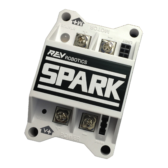
1 SPARK OVERVIEW The REV Robotics SPARK Motor Controller is 12V 60A PWM-controlled brushed DC motor controller designed for FIRST® Robotics Competition robots. The Spark features 60A continuous current with passive cooling, bi-directional limit switch inputs for smart mechanism control, an RGB LED status indicator, and a button-activated brake/coast mode. -
Page 5: Feature Summary
Compatible with #6 and #8 "yellow" ring terminals RGB Status LED Detailed mode and operation feedback 1.2 KIT CONTENTS The following items are included with each SPARK Motor Controller: 1 - SPARK Motor Controller 1 - PWM Cable - 36" - 22 AWG ... -
Page 6: Specifications
Full-forward corresponds to positive output voltage (+V d. If a valid pulse isn't received within the timeout period, the SPARK will disable its output. e. Input deadband is added to each side of the neutral pulse width. Within the deadband, output state is neutral. -
Page 7: Feature Description
2.1.1 SCREW TERMINALS The SPARK has four M3 sized screw terminals; two each for power and motor connections. Each screw has a clamping washer that improves the contact area and clamping force compared to plain screw heads. Table 2-1 lists the recommended crimp-terminal sizes and styles. -
Page 8: Motor Output
2.1.2 MOTOR OUTPUT Motor output terminals are located above the SPARK logo and are marked with raised lettering. A raised "+" and "−" sign indicate the polarity of the motor terminals. See Figure 2-1 for more details. It is recommended to follow a polarity convention when connecting motors to multiple SPARKs so that each motor responds in a predictable manner to the same input signals. -
Page 9: Speed And Direction Control
2.2.1 SERVO-PWM CONNECTION The SPARK accepts a standard 3-wire servo/PWM cable in the port marked PWM in raised lettering. Please refer to the connection diagram in Figure 2-2 or the SPARK housing for polarity indicators. Align the ground/negative wire with the B marking on the case. -
Page 10: Heat Management
Figure 2-3 Heat Sink As seen in Figure 2-3, the heat sink is located at the center of the SPARK. For most applications, a cooling fan isn't necessary, however, airflow should be kept in mind when using the SPARK in high-load applications. The heat sink is electrically isolated from the SPARK circuit board and components. -
Page 11: Limit Switch Inputs
2.4.1 LIMIT SWITCH OPERATION When the signal (s) pin is shorted to the ground (-) pin, the SPARK will override an input command for the corresponding direction and force the SPARK to its neutral state. The STATUS LED will turn white and pulse the corresponding direction color when either of the two limits are triggered and overriding the input command. -
Page 12: Operating Modes
The MODE button is used to switch between the three modes and to reset the SPARK to its factory defaults. It is located near the power input terminals and is labeled as MODE in raised lettering on the SPARK housing. See Figure 2-5. -
Page 13: Calibration
3. Return the signal to the desired neutral value. 4. Release the MODE button. If the calibration routine was successful, the status LED will blink white and green for several seconds while the SPARK immediately begins responding to the new signal range. -
Page 14: Status Led
The SPARK can display information about its current mode of operation via its tri-colored STATUS LED. The STATUS LED is located next to the motor output terminals and is labeled as STATUS with raised lettering on the SPARK housing. Figure 2-6 shows the status codes associated with each operating state of the SPARK. -
Page 15: Appendix Adimensions
APPENDIX A DIMENSIONS All dimensions are in inches. REV-11-1100-UM-00 Copyright © 2016 REV Robotics, LLC... -
Page 16: Appendix Bthermal Data
APPENDIX B THERMAL DATA REV-11-1100-UM-00 Copyright © 2016 REV Robotics, LLC... -
Page 17: Appendix Clinearity Data
The following data was taken with a free spinning CIM motor and a 12V power source. The flat zone in the middle represents the 40µs input deadband on either side of the neutral pulse width. REV-11-1100-UM-00 Copyright © 2016 REV Robotics, LLC... -
Page 18: Appendix Dschematic
APPENDIX D SCHEMATIC Appendix D shows the schematic for the REV Robotics SPARK Motor Controller. REV-11-1200-UM-00 Copyright © 2016 REV Robotics, LLC... - Page 19 STATUS LED CATHODE 0.1uF OPTO-ISO-TLP118 SERVO_IN PWM INPUT LED-RED LED-GREEN LED-BLUE MODE BUTTON SW-TACT-PTS645SM43SMTR92 DESIGNER REVISION DATE BUTTON 1/9/2016 PROJECT SPARK Motor Controller DESCRIPTION Brushed DC Motor Controller WWW.REVROBOTICS.COM 60A Continuous, 12V FILENAME PART NO. SHEET 1 OF RR-SPARK-BD-B.sch REV-11-1200...
Need help?
Do you have a question about the SPARK and is the answer not in the manual?
Questions and answers