
Related Manuals for REV Robotics BLINKIN


Summary of Contents for REV Robotics BLINKIN
- Page 1 BLINKIN LED DRIVER USER'S MANUAL REV-11-1105-UM-0 Copyright © 2018 REV Robotics, LLC...
-
Page 2: Table Of Contents
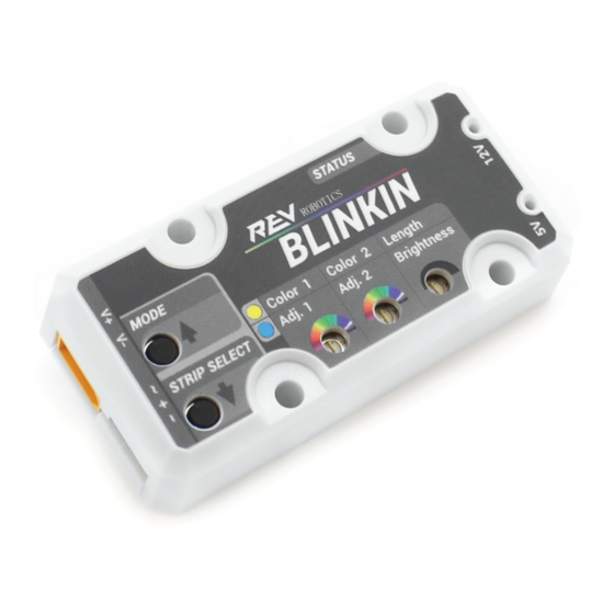
COMPETITION ROBOTICS APPLICATION IDEAS ...................... 12 PHYSICAL DIMENSIONS ..............................13 LED PATTERN TABLE ................................14 LIST OF FIGURES Figure 1: Blinkin Connections and Indicators ..........................3 LIST OF TABLES Table 1: Kit Contents ..................................3 Table 2: Status LED Blink Codes ..............................5 Table 3: WPI Motor Control Output PWM Range ......................... -
Page 3: Overview
1 OVERVIEW The Blinkin is designed to make it straight forward to add controllable LEDs to a robot, cart, or any other project which would benefit from some extra lumens without needing any specialized programming. The Blinkin is a compact, all-in- one solution which can control LEDs in a stand-alone mode with just a 12V power source or in a dynamic mode, changing patterns by supplying a standard servo-style PWM signal. -
Page 4: Electrical Ratings
1.4 SUPPORTED LED STRIP TYPES The BLINKIN can drive either 12V RGB LEDs or 5V Individual addressable LED strips. Each strip type has its own benefits and drawbacks depending on what type of light display is desired. -
Page 5: Setup And Configuration
Section 1 for details 2.1 GETTING STARTED 1. Connect 12V power to the Blinkin using the yellow XT30 2. Select either a 12V or 5V Addressable LED strip and connect it to the Blinkin via the LED cable adapter (REV-11- 1196) 3. -
Page 6: Setup Mode
Select which pattern is displayed with there is not PWM input (e.g. a disabled FRC robot) 1. Power up the Blinkin as described in Section 2.1. The LED strip selected cannot be changed during setup mode, so ensure that the desired strip is connected and running before continuing. -
Page 7: Pwm Control
Valid input pulse widths are from 1000us to 2000us. 1. Connect the Blinkin to a PWM control port on the roboRIO (or other controller) using a standard PWM cable. 2. Using the programming language of your choice, generate a PWM signal. -
Page 8: First Robotics Programming Example
2322 From Table 3, the SPARK motor controller type output directly matches the input to the Blinkin, which makes the math to convert the -1 to 1 code range to the 1000-2000us Blinkin input range the simplest. Other control types, including servo, from the roboRIO can also be used, but the user will need to scale input range correctly to ensure they are sending only a valid PWM range and that they can select the desired LED pattern. -
Page 9: Pattern Adustments
2. Using the small included screwdriver and change Adj.1 Adj.2 and brightness to change the pattern behavior 2.6 FACTORY RESET The Blinkin can store custom user setting in EEPROM so that it persists through power cycles, see Section 2.2 for details. Restore the Blinkin to factory default settings using the following procedure: 1. -
Page 10: Example Applications
Always be sure to read the relevant rules and use appropriate gauge wiring before using anything on your competition robot. After wiring you Blinkin into your robot, follow the setup instructions in Section 2.2 and follow the instructions on PWM control in Section 2.3 as desired. -
Page 11: First Tech Challenge
3.2 FIRST TECH CHALLENGE Please note that the Blinkin is NOT competition legal for the 2017-2018 FTC season. The following wiring information is for adding LEDs for demonstrations and unofficial events. REV-11-1105-UM-0 Copyright © 2018 REV Robotics, LLC... -
Page 12: Stand-Alone Wiring
3.3 STAND-ALONE WIRING The Blinkin can run in a stand-alone operation mode when there is no way to generate a PWM signal, or a single output pattern is all that is needed. In this mode the Blinkin will be operating in Normal Mode with no input signal (blue blinking LED) and will default to the programmed no input signal pattern (factory setting is pattern 29 –... -
Page 13: Physical Dimensions
4 PHYSICAL DIMENSIONS REV-11-1105-UM-0 Copyright © 2018 REV Robotics, LLC... -
Page 14: Led Pattern Table
Fixed Palette Pattern Beats per Minute, Lava Palette Pattern Density Speed Brightness 1195 -0.61 Fixed Palette Pattern Beats per Minute, Forest Palette Pattern Density Speed Brightness 1205 -0.59 Fixed Palette Pattern Fire, Medium Brightness REV-11-1105-UM-0 Copyright © 2018 REV Robotics, LLC... - Page 15 Brightness 1515 0.03 Color 1 Pattern Heartbeat Slow Brightness 1525 0.05 Color 1 Pattern Heartbeat Medium Brightness 1535 0.07 Color 1 Pattern Heartbeat Fast Brightness 1545 0.09 Color 1 Pattern Breath Slow Brightness REV-11-1105-UM-0 Copyright © 2018 REV Robotics, LLC...
- Page 16 Brightness 1835 0.67 Solid Colors Gold Brightness 1845 0.69 Solid Colors Yellow Brightness 1855 0.71 Solid Colors Lawn Green Brightness 1865 0.73 Solid Colors Lime Brightness 1875 0.75 Solid Colors Dark Green Brightness REV-11-1105-UM-0 Copyright © 2018 REV Robotics, LLC...
- Page 17 Blue Violet Brightness 1955 0.91 Solid Colors Violet Brightness 1965 0.93 Solid Colors White Brightness 1975 0.95 Solid Colors Gray Brightness 1985 0.97 Solid Colors Dark Gray Brightness 1995 0.99 Solid Colors Black Brightness REV-11-1105-UM-0 Copyright © 2018 REV Robotics, LLC...
Need help?
Do you have a question about the BLINKIN and is the answer not in the manual?
Questions and answers