
Related Manuals for Godex HD830i


Summary of Contents for Godex HD830i
- Page 1 HD830i BARCODE PRINTER USER MANUAL User Manual : HD830i Version : Rev.A Issue Date : 2017.03 : 920-016611-00...
-
Page 2: Table Of Contents
1 Ba rc o d e Printe r ............................1 1- 1 Pa c ka g e C o nta ins ........................2 1- 2 Ba rc o d e Printe r Intro duc tio n 2 Ba rc o d e Printe rInsta lla tio n ..........................4 ............................ - Page 4 FC C C O MPLIANC E STAT EMENT FO R AMERIC AN USERS Fe d e ra l C o mmunic a tio n C o mmissio n Inte rfe re nc e Sta te me nt T his e q uip me nt ha s b e e n te ste d a nd fo und to c o mp ly with the limits fo r a C la ss B d ig ita l d e vic e , p ursua nt to Pa rt 15 o f the FC C Rule s.
- Page 5 SAFETY INSTRUCTIONS Please read the following instructions carefully. Keep the equipment away from humidity. Before you connect the equipment to the power outlet, please check the voltage of the power source. Make sure the printer is off before plugging the power connector into the power jack.
-
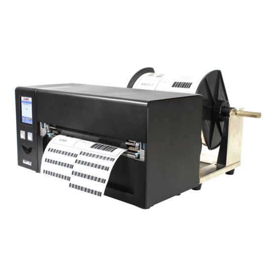
Page 6: Ba Rc O D E Printe R
(Pa c ka g e c o nte nt a nd Lo g o style m a y va ry pe r re g io n Ba rc o d e Printe r HD830i Label Roll Stopper Me d ia Sa m p le... -
Page 7: Ba Rc O D E Printe R Intro Duc Tio N
1- 2 Ba rc o d e Printe r Intro duc tio n Fro nt Vie w Top Cover Touch Screen Power Key Feed Key Front Panel Re a r Vie w (Inte rfa c e m ig ht d iffe re d p e r O p tio na l inte rfa c e ) Paper Path Calibration Key Ethernet... - Page 8 O pe n T o p C o ve r Ribbon Rewind TPH Pressure Adjust knob Print Frame Hook (Left) Print Line Adjust Knob. (Left) Ribbon Tension Adjust Knob. (Left) TPH Module Print Frame Hook (Right) Hook Print Line Adjust Knob (Right) Ribbon Tension Adjust Knob (Right) TPH Module Paper...
-
Page 9: Ba Rc O De Printe Rinsta Lla Tio N
2 Ba rc o de Printe rInsta lla tio n 2- 1 Me dia Insta lla tio n Lift up the to p c o ve r... -
Page 10: 2- 2Printing Me C Ha Nism O Pe Ning
2- 2 Printing Me c ha nism O pe ning Push the Print fra m e ho o k o n the sid e to he a d up the p rint fra m e . Print Frame Hook (Left) Lift up the print frame Push... -
Page 11: 2- 3Rib B O N Insta Lla Tio N
2- 3 Rib b o n Insta lla tio n (4 inc h Rib b o n ) Plug a ne w rib b o n ro ll into the rib b o n Sha ft Follow the direction Ribbon Supply New ribbon roll Ribbon Shaft... -
Page 12: (8 Inc H Rib B O N )
(8 inc h Rib b o n ) Follow the direction Ribbon Supply Ribbon shaft New ribbon roll Insta ll the e m p ty rib b o n c o re into rib b o n sha ft Follow the direction Ribbon Rewind Ribbon shaft Empty Ribbon Core... - Page 13 Insta ll the Rib b o n into the Ba rc o de Printe r Fo llo w the b e lo w d ra wing to insta ll the rib b o n in p o sitio n. Put the Ribbon Rewind Assy into position Rolling to flat surface.
-
Page 14: L A B E L Insta Lla Tio N
2- 4 L a b e l Insta lla tio n L a b e l Ro ll Ass’y Put the la b e l ro ll into m e d ia sp ind le a nd the n insta ll the la b e l ro ll sto p p e r o n the b o th sid e to m a ke the m e d ia ro lle r in p o sitio n. - Page 15 L a b e l Insta lla tio n Ste p 1. Fo llo w ing the a rro w m a rk a nd No . to p ut the la b e l ro ll ho ld e r into p o sitio n. Position Pin Hook Ste p 2.
- Page 16 Ste p 4. Put the la b e l p a ss thro ug h the la b e l g uid e a nd the n a d just the suita b le la b e l w id th a c c o rd ing to .
-
Page 17: C O Nne C Tio N With Pc
( rib b o n ) insta lla tio n, the n p o w e r o n the p rinte r, w a it the sta tus turne d to re a d y. 4. Afte r the m e d ia HD830i Ba rc o d e Printe r (T he inte rfa c e mig ht b e d iffe re d up o n... -
Page 18: Drive R A Nd G O La B E L Insta Lla Tio N
2- 4 Drive r a nd G o la b e l Insta lla tio n Inse rt the Sup e r Wiza rd C D in the C D/ DVD d rive o f the ho st c o m p ute r a nd the Ste p.01 insta lla tio n p ro g ra m sho uld p o p up a uto m a tic a lly. - Page 19 As the p rinte r d rive r a nd G o La b e l a re insta lling , a sc re e n w ill d isp la y a p ro g re ss b a r. Ste p.04 While d o w nlo a d ing c o m p le te d yo u w ill se e Insta lla tio n c o m p le te d .
- Page 20 O nc e the insta lla tio n is c o m p le te , yo u c a n sta rt to m a ke a nd p rint la b e ls with G o La b e l Ste p.06 o r thro ug h the p rinte r d rive r.
-
Page 21: Wiza Rd C D O The R C Ho Ic E Insta Lla Tio N
2- 10 Wiza rd C D O the r C ho ic e Insta lla tio n C lic k “ O T HER C HO IC ES” to ne xt sc re e n a nd se le c t “ PRINT ER DRIVERS” . Ste p .01 C lic k “... - Page 22 T he Drive r Wiza rd w ill g uid e yo u thro ug h the insta lla tio n p ro c e d ure . Se le c t "Insta ll p rinte r Ste p.04 d rive rs" a nd c lic k “ Ne xt” . With a USB c o nne c tio n, se a rc h m o d e ls suc h a s the rig ht d ia g ra m p rinte r d e vic e .
- Page 23 Drive r insta lla tio n c o m p le te d . Ste p.07...
-
Page 24: Ba Rc O De Printe R O Pe Ra Tio N
3 Ba rc o de Printe r O pe ra tio n 3- 1 Ba rc o d e Printe r O pe ra tio n Inte rfa c e Touch Panel (LCD Display) Feed Key Standby Key Sta ndb y ke y Ma ke sure the p o w e r sw itc h is o n, a nd w he n p re ss the “... - Page 25 3- 2 L C D O pe ra tio n Intro d uc tio n...
- Page 29 Label has been printed...
-
Page 30: L A N Se Tting O Pe Ra Tio N Instruc Tio N
3- 3 L A N Se tting O pe ra tio n Instruc tio n Ma in Ma nu... - Page 31 時間設定,例如:年、月、日、時、分、可見...
- Page 34 L C D O pe ra tio n Whe n Ba rc o d e Printe r is Re a d y, the LC D w ill d isp la y “ Re a d y” And the n the p rinte r is re a d y to p rint If the re is a ny e rro r o c c ur, the re w ill b e Erro r Me ssa g e sho w s o n the LC D.
- Page 35 3- 4 L a b e l size c a lib ra tio n a nd Se lf T e st Pa g e T he p rinte r c a n a uto m a tic a lly d e te c t a nd sto re la b e l he ig ht. T ha t m e a ns the ho st c o m p ute r d o e s no t ne e d to tra nsm it the la b e l he ig ht to the p rinte r.
- Page 36 Auto - C a lib ra tio n 「 C a lib ra tio n ke y (C -Butto n) 」 Yo u c o uld p re ss the c a lib ra tio n ke y w hile me d ia b e e n re p la c e d o r m e d ia e rro r to a d just the m e d ia size .
-
Page 37: Erro R Me Ssa G E
3- 5 Erro r Me ssa g e If the re is a ny e rro r o c c urre d d uring the p rinting , LC D w ill d isp la y the Erro r m e ssa g e a nd a lso b uzze r a s w a rning . - Page 40 3- 6 C o nne c te d with USB De vic e s...
- Page 41 No te...
-
Page 42: Insta Lling The Ne Tse Tting So Ftwa Re
Insta lling the Ne tSe tting so ftwa re T he Ne tSe tting so ftw a re is use d to m a na g e the ne tw o rk c o nfig ura tio ns w he n c o nne c ting the p rinte r via Ethe rne t p o rt. - Page 43 O nc e the insta lla tio n is c o m p le te d , yo u w ill se e the Ne tSe tting ic o n o n yo ur d e skto p a s Ste p.05 rig ht d ia g ra m .
-
Page 44: T He Inte Rfa C E O F Ne Tse Tting
4- 2 T he Inte rfa c e o f Ne tSe tting G o DEX p rinte r c a n a lso b e use d thro ug h a ne tw o rk c o nne c tio n (a s a re m o te ne tw o rk p rinte r), m a ke sure the p rinte r c o nne c te d to the Inte rne t a nd the p o w e r c o rd , yo u c a n use the Inte rfa c e o f Ne tSe tting to se a rc h c o nne c te d ne tw o rk p rinte rs. - Page 45 IP Se tting T he IP Se tting ta b c a n c ha ng e the p rinte r na m e , Po rt num b e r, G a te w a y se tting a nd the p a ssw o rd fo r c o nfig uring the p rinte r.
- Page 46 Ale rt Pa th Se tting Ne tSe tting w ill se nd the a le rt m e ssa g e s to d e sig na te d m a il a c c o unt whe n the e rro r ha p p e ne d o n p rinte r.
- Page 47 Ale rt Me ssa g e Se tting Fo r the a le rt m e ssa g e no tific a tio n func tio n, yo u c a n d e c id e w hic h e rro r c a se s ne e d to b e se nt o ut to the o p e ra to r.
- Page 48 Printe r C o nfig ura tio n Se t o r c ha ng e the c o nfig ura tio ns o f c o nne c te d p rinte r. Mo st o f ke y se tting s fo r the p rinte r o p e ra tio n c a n b e d o ne b y this se tting p a g e .
- Page 49 Use r C o m m a nd T he “ Use r C o m m a nd ” ta b p ro vid e s a c o m m unic a tio n inte rfa c e fo r o p e ra to r to c o ntro l the p rinte r. Inp ut p rinte r c o m m a nd s in "Inp ut C o m m a nd "...
- Page 50 Firm wa re Do wnlo a d O n “ Firm w a re Do w nlo a d ” ta b , the c urre nt ve rsio n o f p rinte r firm w a re will b e sho w e d o n the sc re e n. If yo u ne e d to up d a te the p rinte r firmw a re , just sp e c ify the file lo c a tio n o f firm w a re file a nd p re ss “...
-
Page 51: Ba Rc O De Printe R O Ptio Ns
5 Ba rc o de Printe r O ptio ns 5- 1 Pre - ste p fo r O ptio ns Insta lla tio n Be fo re insta ll the o p tio ns, p le a se fo llo w the p re -Ste p 1 Po we r o ff Ba rc o de Printe r (Ple a se m ust b e turn o ff the p o w e r b e fo re a ny o p tio ns insta lla tio n) O pe n the T o p C o ve r... -
Page 52: C Utte R Insta Lla Tio N
5- 2 C utte r Insta lla tio n C utte r pa rts intro duc tio n Cutter cable Front cover Front cover C utte r Mo dule Insta lla tio n Ste ps: (Fo llo w ing Ste p s m ust b e und e r p rinte r p o w e r o ff c o nd itio n) Step 1. - Page 53 Ste p 2. (No . 1) Re le a se the T PH lo c k (No . 2) Fo llo w the d ire c tio n to o p e n the p rint fra me . (No . 3 a nd 4 ) T a ke o ff the fro nt p a ne l Ste p 3.
- Page 54 031-H83003-000 5- 3 Wi- Fi Mo dule Insta lla tio n Ste p 1. Re m o ve the re a r pla te Ste p 3. Co nne c t the c a b le into po sitio n Ste p 2.
- Page 55 、 031-H83004-000 031-H83002-000 5- 4 Blue to o th & Pa ra lle l p o rt a da pto r m o dule Ste p 1. Re m o ve the re a r pla te Ste p 2. Insta ll the Blue to o th m o dule into the re a r pla te Ste p 3.
- Page 56 5- 4 Ma in Bo a rd C o nne c te r Po sitio n 項目 內容 項目 內容 Cutter & Label Dispenser WiFi Motor Calibration Button POWER Ethernet Port RS-232 Port LCD panel USB Port Label Sensor(See-Through) USB HOST Door Open Label Sensor (Reflective) Ribbon Out Sensor...
-
Page 57: Ma Inte Na Nc E A Nd Adjustm E Nt
6 Ma inte na nc e a nd Adjustm e nt 6- 1 Print He a d Re pla c e m e nt Ste p 1. (No . 1 ) Re le a se the T PH lo c k. (No . -
Page 58: Print L Ine Adjustm E Nt
6-2 Print Line Ad justm e nt Lift up the to p c o ve r. Use the fla t sc re w d rive r Print Line Ad justm e nt Sc re w T PH p rint line a d justme nt: T o ha ve g o o d p rint q ua lity in ha rd ne ss o r thic ke r m e d ia , we will sug g e st to m o ve the p rint line a little b it fo rwa rd (p a p e r fe e d ing d ire c tio n) . - Page 59 6- 3 Rib b o n T e nsio n Adjustm e nt Lift up the to p c o ve r Use the fla t sc re w d rive r T e nsio n Ad just Sc re w Clockwise : Tighten the tension Counter Clockwise : Loosen the tension...
-
Page 60: Print He A D C Le A Ning
6- 4 Print He a d C le a ning Dirt o n the p rint he a d o r rib b o n, o r g lue re sid ue fro m the la b e l sto c k m a y re sult in ina d e q ua te p rint q ua lity. -
Page 61: Print He A D Pre Ssure A Djustm E Nt
6- 5 Print He a d Pre ssure A djustm e nt Whe n p rinting o n sp e c ia l m e d ia (w ith va rying m a te ria l thic kne ss), the p rint q ua lity m a y suffe r. Yo u w ill the n ne e d to a d just the p rint he a d p re ssure . -
Page 62: Rib B O N Wrinkle Adjustm E Nt
6- 6 Rib b o n Wrinkle Adjustm e nt T he use o f d iffe re nt rib b o n m a te ria ls m a y c a use w rinkling o f the rib b o n, w hic h in turn a ffe c ts the p rint re sult a s illustra te d b y the e xa m p le s in (a ) a nd (b ). -
Page 63: C Utte R Erro R T Ro Ub Le Sho O Ting
6- 7 C utte r Erro r T ro ub le Sho o ting While using the c utte r, p a p e r ja m s m a y o c c ur. Ple a se fo llo w the b e lo w ste p s to c le a n the p a p e r ja m . A so c ke t he a d sc re w fo r a d justing the c utte r is lo c a te d o n the b o tto m o f c utte r m o d ule , a s sho w n in b e lo w illustra tio n. -
Page 64: T Ro Ub Le Sho O Ting
6- 8 T ro ub le Sho o ting Pro b le m So lutio n T he printe r is switc he d o n b ut the displa y ♦ 。 C he c k the p o we r sup p ly. do e s no t lig ht up. -
Page 65: Appe Ndix - Printe R Sp E C Ific A Tio N
Appe ndix - Printe r Sp e c ific a tio n... -
Page 66: Appe Ndix - C O M M Unic A Tio N Po Rt Spe C Ific A Tio N
Appe ndix - C o m m unic a tio n Po rt Spe c ific a tio n...
Need help?
Do you have a question about the HD830i and is the answer not in the manual?
Questions and answers