Table of Contents
Advertisement
Quick Links
Advertisement
Table of Contents

Subscribe to Our Youtube Channel
Related Manuals for PairGain HiGain ELU-819


Summary of Contents for PairGain HiGain ELU-819
- Page 1 ETSI L UICK NSTALLATION UIDE Model List Number Part Number CLEI Code ELU-819 150-2230-01 VACHNRXC HLU-819 I AIN STATUS ECHNOLOGIES NGINEERING ERVICES 350-819-300-01 ECTION...
- Page 2 No license is granted by implication or otherwise under any patent or patent rights of PairGain Technologies. PairGain Technologies reserves the right to change specifications at any time without notice.
- Page 3 350-819-300-01, Revision 01 Using This Guide SING UIDE The following conventions are used in this guide: • Monospace type indicates screen text, including text you type at a screen prompt. • ENTER Keys you press are indicated by small icons such as .
- Page 4 Documentation 350-819-300-01, Revision 01 OCUMENTATION If you have comments on this PairGain document, send an email to technical_publications@pairgain.com. Type the product name and the section number of the document in the subject area of the email message. The following related technical practices can be downloaded from the Customer Site portion of the PairGain Web page at www.pairgain.com using...
- Page 5 • Check the packing list to ensure complete and accurate shipment of each listed item. If the shipment is short or irregular, contact PairGain as described in the Warranty located inside the back cover. If you must store the equipment for a prolonged period, store the equipment in its original container.
- Page 6 Safety 350-819-300-01, Revision 01 January 10, 2000 ELU-819 List 1...
-
Page 7: Table Of Contents
350-819-300-01, Revision 01 Table of Contents ABLE OF ONTENTS Overview _______________________________________________ 1 Front Panel _____________________________________________ 3 Installation _____________________________________________ 6 Installing the ELU-819 into a 3192 Shelf ........ 7 Installing a UTU into the ERE-811 Remote Enclosure ... 8 UTU Jumper Settings ..........8 UTU Installation ............ - Page 8 Table of Contents 350-819-300-01, Revision 01 Appendix C - Product Support_____________________________34 Technical Support..............34 World Wide Web..............34 Returns..................35 Certification and Warranty _________________ Inside Back Cover viii January 10, 2000 ELU-819 List 1...
- Page 9 350-819-300-01, Revision 01 List of Figures IST OF IGURES 1. Typical ELU-819 List 1 Application (E1 to Dual-Port Operation)..1 2. ELU-819 List 1 Front Panel ..............3 3. E1 (G.703) Access Jacks ................ 5 4. Installing the ELU-819 into a 3192 Shelf ..........7 5.
- Page 10 List of Tables 350-819-300-01, Revision 01 IST OF ABLES 1. ELU-819 List 1 Front-panel Status LED Description ......4 2. Console Screen Navigation Keys ............17 3. Console Screen Menus................20 4. Settings in Config System Settings Menu ..........21 5. Settings in Config LTU and NTU Interface Menus ......23 6.
-
Page 11: Overview
350-819-300-01, Revision 01 Overview VERVIEW ® ™ PairGain HiGain-ETSI Line Unit ELU-819 List 1 installs in any 3192-compliant chassis and interfaces with the HiGain-ETSI Universal Termination Units UTU-801 List 5, UTU-802 List 5, and UTU-804 List 5. The ELU-819 and the UTUs provide the Central Office (CO) and remote terminal (RT) sides of a repeaterless, High bit-rate Digital Subscriber Line (HDSL), respectively. - Page 12 350-819-300-01, Revision 01 The ELU-819 List 1 is part of the Open Span Termination Shelf (OSTS) family of products supported by the PairGain Wideband System 3190. With this card, the entire PairGain ETSI family of remote Customer Premise Equipment (CPE), which includes UTU-801, UTU-802, and UTU-804 List 5, can be subtended to the Wideband System 3190 to provide standard Digital Service Unit (DSU) and Channel Service Unit (CSU) data port interfaces.
-
Page 13: Front Panel
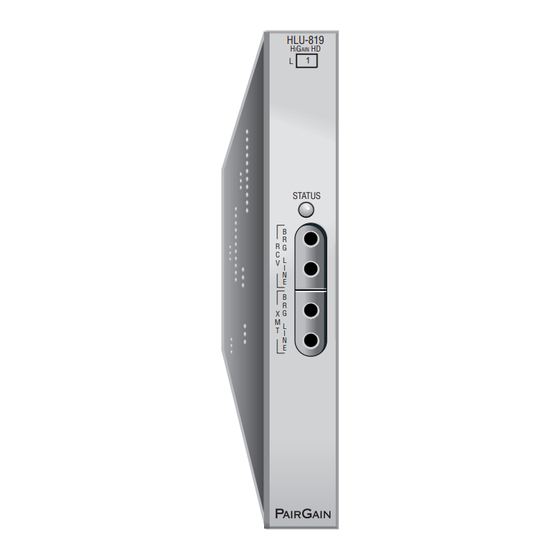
350-819-300-01, Revision 01 Front Panel RONT ANEL Figure 2 shows the ELU-819 front panel. Table 1 on page 4 describes the front-panel components. A diagram of the line and bridging access jacks is shown in Figure 3 on page Figure 2. ELU-819 List 1 Front Panel ELU-819 List 1 January 10, 2000... -
Page 14: Elu-819 List 1 Front-Panel Status Led Description
Front Panel 350-819-300-01, Revision 01 Table 1. ELU-819 List 1 Front-panel Status LED Description Item Function Status LED Displays synchronization state and alarm status for HDSL Loop. Steady Green HDSL loop is ready to transmit and receive data across all spans. -
Page 15: E1 (G.703) Access Jacks
350-819-300-01, Revision 01 Front Panel Figure 3. E1 (G.703) Access Jacks ELU-819 List 1 January 10, 2000... -
Page 16: Installation
Installation 350-819-300-01, Revision 01 NSTALLATION This section provides instructions for setting up the ELU-819 and installing the UTU-801 List 5, UTU-802 List 5, or UTU-804 List 5 into the ERE-811 List 2 remote unit. The remote unit can be powered from either the ELU-819 (must be configured) or locally, using either 110 Volts, Alternating Current (VAC) or -48 Vdc power. -
Page 17: Installing The Elu-819 Into A 3192 Shelf
350-819-300-01, Revision 01 Installation ELU-819 3192 S NSTALLING THE INTO A HELF Figure 4. Installing the ELU-819 into a 3192 Shelf Align the ELU-819 with the enclosure slot guides and slide the unit in. (Figure Push the unit back until it touches the backplane card-edge connector and is firmly seated. -
Page 18: Installing A Utu Into The Ere-811 Remote Enclosure
Installation 350-819-300-01, Revision 01 ERE-811 R NSTALLING A INTO THE EMOTE NCLOSURE UTU Jumper Settings Jumpers must be set on the UTU units if using a 120 Ω interface or if grounding your G.703 cables at the data port on the shelf or remote enclosure. The locations of these jumpers (P8, P11, and P12) are shown in Figure Figure 5. - Page 19 350-819-300-01, Revision 01 Installation To set the jumpers on the UTU line units: Jumper P8 complies with the ITU G.703 requirement that an option be provided to allow the connection of the outer conductor of the coaxial pair or the screen of the symmetrical pair to earth (frame) ground at the G.703 input data port.
-
Page 20: Utu Installation
Installation 350-819-300-01, Revision 01 UTU Installation ERE-811 Enclosure Slot guides Line card Captive screw Captive screw Figure 6. Installing a UTU into the ERE-811 Remote Enclosure Align the card with the enclosure slot guides at the left and right sides of the enclosure opening (Figure Push the card into the enclosure until the front panel is flush with the... - Page 21 350-819-300-01, Revision 01 Installation Connect the Nx64K data port cable DB-25F (Figure 7), if applicable. The following adapters can be used when connecting the cable: • ECA-800 List 1 (DB-25M to M-34F, V.35) • ECA-801 List 1 (DB-25M to DB-15F, X.21) •...
-
Page 22: Hdsl Startup And Synchronization
HDSL Startup and Synchronization 350-819-300-01, Revision 01 HDSL S TARTUP AND YNCHRONIZATION Power-up the shelf where the ELU-819 is installed and observe the following: The Status LED flashes green once per second as the unit attempts to establish synchronization. After approximately 30 seconds, confirm one of the following: •... -
Page 23: System Configuration
350-819-300-01, Revision 01 System Configuration YSTEM ONFIGURATION A maintenance terminal is used to access the line unit console screens and configuration menus. Through these screens and menus, the HDSL system is configured, monitored, tested, and its circuit inventory can be displayed. The console screens must be viewed through the HMU-319 craft port or Operating System (OS) port located at the back of the Wideband System 3190, or through a TELNET session over an Ethernet Local Area Network... -
Page 24: Maintenance Terminal Connection
System Configuration 350-819-300-01, Revision 01 AINTENANCE ERMINAL ONNECTION To connect a maintenance terminal: Connect a standard serial cable from the maintenance terminal COM port to the front-panel craft port of the HMU-319. The pinouts for the craft port and maintenance terminal connectors are shown in Figure 8 on page Configure the maintenance terminal for the following communication... -
Page 25: Connector Pinouts
350-819-300-01, Revision 01 System Configuration Figure 8. HMU-319 Craft Port and Maintenance Terminal Connector Pinouts ELU-819 List 1 January 10, 2000... -
Page 26: Logging On
System Configuration 350-819-300-01, Revision 01 OGGING Logon procedure may vary depending on the software revision level on the HMU-319. Consult the software manual for your particular system (refer to “Documentation” on page iv “Appendix C - Product Support” on page 34). -
Page 27: Navigating Menus
350-819-300-01, Revision 01 System Configuration AVIGATING ENUS Use the keys described in Table 2 to navigate the console screens and menus. Table 2. Console Screen Navigation Keys These Keys Perform this Function Alpha-numeric Type the underlined or highlighted letter to select and execute a menu keys item. - Page 28 System Configuration 350-819-300-01, Revision 01 Table 2. Console Screen Navigation Keys (Cont.) These Keys Perform this Function Exits the current screen and returns to the previous screen. Selections made on the current screen are discarded. Press in a text field to cancel the text entry and restore the old value.
-
Page 29: Console Screen Menu Structure
350-819-300-01, Revision 01 System Configuration ONSOLE CREEN TRUCTURE The Console screen displays a row of dropdown menus that serve as a guide to the appropriate option or screen. Figure 9 shows the structure of the Console screen menus, which pertains only to the local configuration and not to the remote. - Page 30 System Configuration 350-819-300-01, Revision 01 Table 3. Console Screen Menus Menu Name Function Main Displays the Main status Console screen to: • View the circuit configuration. • View performance summary information. • View alarm summary information. Monitor Monitors the past 24-hour performance of the LTU interfaces, NTU interfaces, or HDSL span.
-
Page 31: System Settings
350-819-300-01, Revision 01 System Configuration YSTEM ETTINGS The settings available in the Config System Settings menu are listed in Table 4. The settings in boldface type are factory default settings. Table 4. Settings in Config System Settings Menu System Setting Description Application mode Select one of the following application modes:... - Page 32 System Configuration 350-819-300-01, Revision 01 Table 4. Settings in Config System Settings Menu (Cont.) System Setting Description Remote Power No selection available. Always displays BOTH. Feed Loop BOTH BOTH displays in UNSTRUCT, STRUCT, and TSP application modes. The LTU (ELU-819) uses Loop 1 and Loop 2 to supply power to the NTU.
-
Page 33: Interface Settings
350-819-300-01, Revision 01 System Configuration LTU (ELU-819) NTU (UTU-801, 802, 804) I NTERFACE ETTINGS The settings available in the Config LTU and Config NTU Interface menus are listed in Table 5. The settings in boldface type are factory default settings. Table 5. - Page 34 System Configuration 350-819-300-01, Revision 01 Table 5. Settings in Config LTU and NTU Interface Menus (Cont.) Field Description AIS Mode Specify the mode used to assert an Alarm Indication Signal (AIS). Used in structured (framed) mode. FULL Asserts an AIS when one loop is down. HALF Asserts an AIS when both loops are down.
-
Page 35: Ltu (Elu-819) And Ntu (Utu-801, 802, Or 804)
350-819-300-01, Revision 01 System Configuration Table 5. Settings in Config LTU and NTU Interface Menus (Cont.) Field Description LL/RL Select whether the LTU and NTU respond to or ignore the Local Loopback (LL) and Remote Loopback (RL) control signals. LTU and NTU ignore LL and RL control signals. LTU and NTU respond to LL and RL control signals. -
Page 36: Reading The Console Screens
System Configuration 350-819-300-01, Revision 01 EADING THE ONSOLE CREENS The UTU-801, UTU-802, and UTU-804 List 5 perform the same functions as a HiGain Remote Unit (an HRU). However, in all console screens, the UTU is referred to as an NTU and the ELU-819 is referred to as an LTU. For proper operation, only NTUs will connect to LTUs. -
Page 37: Information Displayed In Main Console Screen
350-819-300-01, Revision 01 System Configuration Table 6. Information Displayed in Main Console Screen Field Description Circuit Configuration G.703 Identifies the LTU and NTU G.703 ports. n TS Indicates the number of G.703 time slots (n) selected for the G.703 application interface. V.35 Identifies the NTU V.35 port. - Page 38 System Configuration 350-819-300-01, Revision 01 Table 6. Information Displayed in Main Console Screen (Cont.) Field Description Performance MAR1 Displays the Margin value for the HDSL Loop 1 interface at the LTU and NTU or displays link status (SIG, ACK, etc.) if link is not up. MAR2 Displays the Margin value for the HDSL Loop 2 interface at the LTU and NTU or displays link status (SIG, ACK, etc.) if link is not up.
-
Page 39: Monitor Screens
350-819-300-01, Revision 01 System Configuration ONITOR CREENS The monitor screens display the signal activity and Performance Monitor (PM) counts at the G.703 LTU (ELU-819) and NTU (UTU-801, UTU-802, or UTU-804) G.703, and Nx64K ports. Table 7 on page 30 lists each field and a description of that field. - Page 40 System Configuration 350-819-300-01, Revision 01 Table 7. Information in Monitor LTU and NTU Interface Screens Field Description LTU Interface (G.703 Port) Errored Seconds The number of one-second intervals in which at least one bipolar (ES) 24 Hour violation (BPV) or one CRC-4 error was detected at the G.703 input Count port during the last 24 hours.
-
Page 41: Monitor Hdsl Span Screens
350-819-300-01, Revision 01 System Configuration HDSL S ONITOR CREENS Table 8 lists the information displayed in the Monitor HDSL Span 1 screen for Loop 1, LTU-1/NTU-1, and Loop 2, LTU-1/NTU-1. Table 8. Information Displayed in Monitor HDSL Span 1 Screen Field Description Current Margin... -
Page 42: Appendix A - Specifications
Appendix A - Specifications 350-819-300-01, Revision 01 A - S PPENDIX PECIFICATIONS This section contains the ELU-819 technical specifications. Maximum Power C 5.0 watts Environmental Operating temperature 0 °C to 50 °C Operating humidity 5% to 95%, non-condensing Altitude 197 ft. (60 m) below sea level to 13,123 ft. (4000 m) above sea level Mounting 3192-type HiGain Management Shelf (HMS) -
Page 43: Appendixb - Compatibility
HMS-357, part number 150-2205-01, -02 – HMS-358, part number 150-2209-01, -02 • PairGain HMS-317, part number 150-1128-21, (28-slot, 23-inch shelf) • PairGain HMS-308, part number 150-1275-01, (8-slot, 3192 mechanics, remote enclosure) The UTU-801, -802, and -804 List 5 are compatible with the following PairGain HiGain ETSI shelves and enclosures. -
Page 44: Appendix C - Product Support
PairGain product and company information can be found at http://www.pairgain.com using any Web browser. To download PairGain product manuals from the Customer Site portion of the PairGain Web page, you need to provide a customer password. If you do not have a password, contact your PairGain sales representative. -
Page 45: Returns
To obtain a return authorization number, you need to provide the original purchase order number to PairGain’s Return Material Authorization (RMA) Department. Call or write PairGain’s RMA Department to ask for an RMA number and any additional instructions. Use the telephone number, fax number or email address listed below: •... - Page 46 Appendix C - Product Support 350-819-300-01, Revision 01 Pack the equipment in a shipping carton. Write PairGain’s address and the RMA Number you received from the RMA Department clearly on the outside of the carton and return to: PairGain Technologies, Inc.
-
Page 47: Certification And Warranty
Do not try to repair the unit. If it fails, replace it with another unit and return the faulty unit to PairGain for repair. - Page 48 Corporate Office 14402 Franklin Avenue Tustin, CA 92780-7013 Tel: 714.832.9922 Fax: 714.832.9924 For Technical Assistance: 800.638.0031...
Need help?
Do you have a question about the HiGain ELU-819 and is the answer not in the manual?
Questions and answers