Table of Contents
Troubleshooting

Related Manuals for PairGain HiGain SOLITAIRE H2TU-C-319 List 1


Summary of Contents for PairGain HiGain SOLITAIRE H2TU-C-319 List 1
- Page 1 SOLITAIRE Technical Practice HiGain Solitaire Line Unit H2TU-C-319 List 1 Part Number: 150-2400-01 CLEI Code: VACHDN0C H2TU-C-319 List 1C Part Number: 150-2400-13 CLEI Code: VACHKNZC ™152-319-100-02•¨ Section 152-319-100-02...
- Page 2 Information furnished by PairGain Technologies is believed to be accurate and reliable. However, no responsibility is assumed by PairGain Technologies for its use; nor for any infringement of patents or other rights of third parties which may result from its use.
- Page 3 Check the packing list to ensure complete and accurate shipment of each listed item. If the shipment is short or irregular, contact PairGain as described in the Warranty located inside the back cover. If you must store the equipment for a prolonged period, store the equipment in its original container.
- Page 4 Inspecting Shipment 152-319-100-02, Revision 02 April 21, 2000 H2TU-C-319 List 1 and List 1C...
-
Page 5: Table Of Contents
152-319-100-02, Revision 02 Table of Contents ABLE OF ONTENTS Overview ____________________________________________________________________________ 1 Features ..............................1 Compatibility .............................2 Applications ............................2 HiGain Solitaire Regenerators ......................3 Front Panel __________________________________________________________________________ 4 Installation___________________________________________________________________________ 8 Verification ............................9 Verification without a Downstream Device ................9 Verification with a Downstream Device ................9 Provisioning Requirements ......................10 Provisioning_________________________________________________________________________ 11 Using the MODE and SEL Buttons (List 1 Only) ................11... - Page 6 Table of Contents 152-319-100-02, Revision 02 Alarm History at the HDSL2 Interface ................34 Using the Event Log to Track System Events................. 35 Troubleshooting _____________________________________________________________________ 37 Front-panel System Alarms......................37 Alarm Option for DLC Feed ..................... 38 Retiring System Alarms ....................38 Remote LOS and AIS Response ..................
- Page 7 5. Configuration Menu - Date and Time ......................15 6. Inventory Screen............................16 7. Configuration Menu ............................17 8. Configuration Menu - Standard Options (Defaults Shown)................18 9. Configuration Menu - PairGain Options (Defaults Shown)................18 10. Configuration Menu - Reset to Factory Defaults ..................22 11. Master Clear ..............................23 12. System Spans..............................24 13.
- Page 8 4. Logon Screen Menus ............................ 14 5. H2TU-C-319 List 1 and List 1C Standard Config Screen Options .............. 19 6. H2TU-C-319 List 1 and List 1C PairGain Config Screen Options .............. 20 7. DS1/DSX-1 24-hour PM Threshold ......................22 8. Monitor Screen Descriptions ........................26 9.
-
Page 9: Overview
High bit-rate Digital Subscriber Line 2 (HDSL2). PairGain products are fully compliant with the HDSL2 standard. Providing full-rate T1 access using just a single copper pair, HDSL2 is a cost-effective solution that offers an open architecture. -
Page 10: Compatibility
Overview 152-319-100-02, Revision 02 • Network Management and Administration (NMA) interface • Margin threshold alarm OMPATIBILITY The H2TU-C-319 is designed to mount in 3192 mechanics shelves. For a list of compatible shelves see “Appendix C - Compatibility” on page PPLICATIONS HiGain Solitaire systems provide a cost-effective, easy-to-deploy method for delivering T1 High Capacity Digital Service (HCDS) over a single copper pair. -
Page 11: Higain Solitaire Regenerators
152-319-100-02, Revision 02 Overview Figure 1. HDSL2 System Model OLITAIRE EGENERATORS For applications without regenerators (doublers), the H2TU-C-319 is directly connected to an H2TU-R remote unit by one HDSL2 cable pair. The H2TU-C-319 List 1 and List 1C are compatible with all HiGain Solitaire H2TU-Rs. -
Page 12: Front Panel
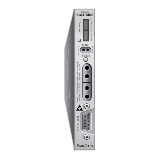
Front Panel 152-319-100-02, Revision 02 RONT ANEL Figure 2 shows the H2TU-C-319 List 1 front panel. Table 1 on page 5 describes the front-panel components. For a list of front-panel display messages, refer to Table 2 on page 6. For pinout diagrams of the H2TU-C card-edge connector and craft port, refer to “Appendix A - Specifications”... - Page 13 152-319-100-02, Revision 02 Front Panel Table 1. Front-panel Description Front-panel Feature Function Front-panel display Displays four-character status, provisioning, and alarm system messages. The front-panel display illuminates when power is initially applied. To conserve power the display only remains on for 5 minutes.
- Page 14 Front Panel 152-319-100-02, Revision 02 Table 2 lists the front-panel display messages. The four-character display reports the code of an alarm, loopback, or diagnostic message and, in some cases, is followed by a second four-character message that modifies the first message with a value or current configuration setting.
- Page 15 152-319-100-02, Revision 02 Front Panel Table 2. Front-panel Display Messages (List 1 Only) (Cont.) Message Full Name Description LOOPBACK MESSAGES continued SMJK Remote SmartJack Loopback DSX-1 signal is looped back to the network at the H2TU-R SmartJack module. DIAGNOSTIC MESSAGES A = xx Maximum Loop Attenuation The Attenuation (A) message appears followed by xx, where xx is the...
-
Page 16: Installation
Upon receipt of the equipment, inspect the contents for signs of damage. If the equipment has been damaged in transit, immediately report the extent of damage to the transportation company and to PairGain Technologies. Figure 3. Installing the H2TU-C-319 into a Shelf When installing an H2TU-C in a chassis, be sure to wear an antistatic wrist strap. -
Page 17: Verification
152-319-100-02, Revision 02 Installation ERIFICATION Once the H2TU-C is installed, verify that it is operating properly. To do this, monitor the following: • Status LED • Status messages reported by the front-panel display (see Table 2 on page Verification without a Downstream Device If there is no downstream device installed: Verify that the H2TU-C powers up. -
Page 18: Provisioning Requirements
Installation 152-319-100-02, Revision 02 ROVISIONING EQUIREMENTS Refer to “Provisioning” on page 11 for instructions on configuring and monitoring the H2TU-C-319. • The H2TU-C-319 List 1 can be provisioned by using the MODE and SEL buttons on the front panel or by accessing the HiGain Solitaire HDSL2 maintenance screens. -
Page 19: Provisioning
152-319-100-02, Revision 02 Provisioning ROVISIONING There are two provisioning methods: • Use the MODE and SEL buttons on the front panel of the H2TU-C-319 (List 1 only) to: – Set system options – Reset the H2TU-C to its factory default settings for system options –... -
Page 20: Resetting To Factory Default Values
Provisioning 152-319-100-02, Revision 02 Resetting to Factory Default Values All user options for the H2TU-C-319 List 1 (Table 5 on page 19) can be set to the factory default values using the MODE and SEL buttons. To set the user options to their default values: Press the SEL button for 6 seconds until the following message appears: DFLT NO Press the SEL button while the DFLT NO message is displayed. -
Page 21: Using A Maintenance Terminal
152-319-100-02, Revision 02 Provisioning SING A AINTENANCE ERMINAL Connecting to a Maintenance Terminal The craft port on the front panel allows you to connect the H2TU-C-319 List 1 to a maintenance terminal (ASCII terminal or PC running a terminal emulation program). Once connected to a maintenance terminal, you can access the maintenance, provisioning, and performance screens. -
Page 22: Logon Screen
Help Provides a glossary of terms used in the HiGain Solitaire HDSL2 maintenance screens, a list of navigational keys, and PairGain contact information. April 21, 2000 H2TU-C-319 List 1 and List 1C... -
Page 23: Provisioning Tasks
Setting Date and Time Monitor Performance Event Log Config Inventory Rlogon Help +----------------------+ | Standard Options -> | PairGain Options -> Date and Time -> +-------------------------------+ | Date (mm/dd/yyyy): 04/21/2000 | Time (hh:mm[:ss]): 12:30:01 +-------------------------------+ ID: xxxx--xxxx--xxxx--xxxx 04/21/00 12:30:01 H2TU-C System: OK Figure 5. -
Page 24: Setting Circuit Id Numbers
Provisioning 152-319-100-02, Revision 02 Setting Circuit ID Numbers The Inventory menu provides product information on all units in the system and allows setting of the circuit and unit identification numbers. Monitor Performance Event Log Config Inventory Rlogon Help -------------------------- Product Information ---------------------------- Unit : H2TU-C... -
Page 25: Making Changes To The System Configuration
Standard and PairGain configuration options. Standard options are those that are supported by HiGain Solitaire units when connected to units from other vendors. PairGain options are an extended set of options that are only available when using HiGain units exclusively. For a description of... -
Page 26: Configuration Menu - Standard Options (Defaults Shown)
| Remote Disconnect Alarm (RDA) : ENA +-----------------------------------------------+ Press <Space> to cycle through settings and <Enter> to activate. ID: xxxx--xxxx--xxxx--xxxx 04/21/00 12:30:01 H2TU-C System: OK Figure 9. Configuration Menu - PairGain Options (Defaults Shown) April 21, 2000 H2TU-C-319 List 1 and List 1C... - Page 27 Standard Config screen options and lists their front-panel display codes. Table 6 on page 20 describes the PairGain Config screen options. Selections in bold typeface are the factory default settings. Table 5. H2TU-C-319 List 1 and List 1C Standard Config Screen Options...
- Page 28 Pattern Figure 24 on page 39 for LOS/AIS response priorities. Enables the H2TU-R to transmit LOS towards the CI for any network loopback. Table 6. H2TU-C-319 List 1 and List 1C PairGain Config Screen Options Front-panel System Settings Display Selection...
- Page 29 152-319-100-02, Revision 02 Provisioning Table 6. H2TU-C-319 List 1 and List 1C PairGain Config Screen Options (Cont.) Front-panel System Settings Display Selection Description Screen Options Code Remote Disconnect Enables a remote DS1 LOS condition at the input to the H2TU-R to generate Alarm an LOS alarm.
-
Page 30: Configuration Menu - Reset To Factory Defaults
Performance Event Log Config Inventory Rlogon Help +----------------------+ | Standard Options -> | PairGain Options -> | Date and Time -> | Master Clear Set Factory Defaults +----------------------+ SETTING FACTORY DEFAULTS...SERVICE *MAY* BE INTERRUPTED! ARE YOU SURE (Y/N)? ID: xxxx--xxxx--xxxx--xxxx... -
Page 31: Clearing The History, Alarm And Event Log Screens
Event Log Config Inventory Rlogon Help +----------------------+ | Standard Options -> | PairGain Options -> | Date and Time -> Master Clear | Set Factory Defaults | +----------------------+ Clear ALL performance, alarm and event log entries. Are you sure (Y/N)? -
Page 32: Monitoring System Activity And Performance
Monitoring System Activity and Performance 152-319-100-02, Revision 02 ONITORING YSTEM CTIVITY AND ERFORMANCE The H2TU-C-319 provides two sets of maintenance screens for monitoring system activity and assessing performance. • The Monitor screens provide a graphical representation of circuit activity and allow initiation of loopbacks. •... -
Page 33: Using The Monitor Screen To View System Activity
152-319-100-02, Revision 02 Monitoring System Activity and Performance SING THE ONITOR CREEN TO YSTEM CTIVITY Press to view the system diagram. Figure 13 shows an armed circuit with an active loopback and alarms. Terms used on the system diagram are defined in the onscreen Help menu glossary. -
Page 34: Using The Performance Screens To View Performance Data
Monitoring System Activity and Performance 152-319-100-02, Revision 02 Table 8. Monitor Screen Descriptions Field Description Active Loopback An active loopback is indicated on the lower third of the Monitor screen. Available loopbacks are indicated by gray text. See Table 15 on page 41 for a summary of the HiGain Solitaire loopback codes and activation methods. -
Page 35: Performance History At The Ds1 Interface
152-319-100-02, Revision 02 Monitoring System Activity and Performance Performance History at the DS1 Interface Figure 14 Figure 15 are examples of an H2TU-R DS1 31-day history and H2TU-C DS1 25-hour history performance screens, respectively, as viewed from the line unit. In addition, there are 48-hour and current history statistic screens for the DS1 interfaces for the H2TU-R and H2TU-C. - Page 36 Monitoring System Activity and Performance 152-319-100-02, Revision 02 Table 9. Acronyms Used on the DS1 Performance History Screens Acronym Description Acronym Description ES-L Errored Seconds - Line SES-P Severely errored seconds - Path Seconds with BPV Seconds with SES or CRC(ESF) 3 20 or (SF) 8 (F...
-
Page 37: Performance History At The Hdsl2 Interface
152-319-100-02, Revision 02 Monitoring System Activity and Performance Performance History at the HDSL2 Interface Figure 16 is an example of a 31-day HDSL2 performance screen as viewed from the H2TU-C. The HDSL2 interface has 31-day, 48-hour, 25-hour, and current statistic screens for the H2TU-C. Table 10 describes the acronyms used in the performance history screens. -
Page 38: Current Statistics Screens For The Ds1 Interface
Monitoring System Activity and Performance 152-319-100-02, Revision 02 Current Statistics Screens for the DS1 Interface Examples of current statistics screens are shown below. Figure 17 Figure 18 show statistics for the DS1 interface at the remote unit and line unit, respectively. These screens report 1-day, 1-hour, and 15-minute statistics. Refer to Table 9 on page 28 for descriptions of the kinds of errors reported on these screens. -
Page 39: Current Statistics For Hdsl2 Interface
152-319-100-02, Revision 02 Monitoring System Activity and Performance Current Statistics for HDSL2 Interface Figure 19 shows statistics for the HDSL2 interface at the H2TU-C. This screen reports 1-day, 1-hour, and 15-minute statistics. Refer to Table 10 on page 29 for descriptions of the kinds of errors reported on this screen. Monitor Performance Event Log... -
Page 40: Using The Performance Screens To View Alarm Data
Monitoring System Activity and Performance 152-319-100-02, Revision 02 SING THE ERFORMANCE CREENS TO LARM To access the alarm history screens: Press to select the Performance screen. SPACEBAR Press the to select an interface (H2TU-C DS1, H2TU-R DS1, H2TU-C HDSL2, or H2TU-R HDSL2), then press ENTER Press the... -
Page 41: H2Tu-R Ds1 Alarm History Screen
152-319-100-02, Revision 02 Monitoring System Activity and Performance Monitor Performance Event Log Config Inventory Rlogon Help H2TU-R DS-1 Alarm History ------------------------------------------------------------------------------ Alarm First Last Status Count RLOS 04/03/00 00:00 04/03/00 00:45 ALARM RAIS LRAI PRM-NE DISABLED PRM-FE DISABLED DBER 04/03/00 00:37 04/03/00 00:45 Press: C(l)ear Alarm History ------------------------------------------------------------------------------... -
Page 42: Alarm History At The Hdsl2 Interface
Monitoring System Activity and Performance 152-319-100-02, Revision 02 Alarm History at the HDSL2 Interface Figure 22 shows the H2TU-C HDSL2 alarm history, and Table 12 describes the alarms. Monitor Performance Event Log Config Inventory Rlogon Help H2TU-C HDSL2 Alarm History ------------------------------------------------------------------------------ Alarm First... -
Page 43: Using The Event Log To Track System Events
152-319-100-02, Revision 02 Monitoring System Activity and Performance SING THE VENT OG TO RACK YSTEM VENTS To view a running log of system events, press to select the Event Log. The Event Log displays the date and time of the 100 most recent events (most recent displayed first) and provides a description of each event. See Table 13 on page 36 for an alphabetical listing of all possible event log messages. - Page 44 Monitoring System Activity and Performance 152-319-100-02, Revision 02 Table 13. Event Log Entry Messages List Event Log Messages Any DS1 Alarm History reset Any DS1 PM register reset Any HDSL2 Alarm History reset Any HDSL2 PM register reset Any Loop Down (any segment) Any Loop Up (any segment) Any provisioning option change: <provisioning mnemonic>: changed from <old>...
-
Page 45: Troubleshooting
152-319-100-02, Revision 02 Troubleshooting ROUBLESHOOTING This section provides information about front-panel system alarms, LOS/AIS response, the OCT55 test procedure, and loopback testing. RONT PANEL YSTEM LARMS Table 14 lists possible H2TU-C-319 List 1 alarm states in order of priority as they appear on the front panel. These alarms correlate with the alarms displayed on the alarm history screens (see “Using the Performance Screens to View Performance Data”... -
Page 46: Alarm Option For Dlc Feed
Troubleshooting 152-319-100-02, Revision 02 Table 14. Front-panel System Alarms (Cont.) Front-Panel Alarm Description To Inhibit: Message PRMN Performance Report H2TU-R PRM-NE BER threshold has been Set DBER threshold to DIS. Messaging - Near End exceeded. PRMF Performance Report H2TU-R PRM-FE BER threshold has been Set DBER threshold to DIS. -
Page 47: Remote Los And Ais Response
152-319-100-02, Revision 02 Troubleshooting Remote LOS and AIS Response Figure 24 shows the different ways the H2TU-R can respond to the network, depending on the configuration of the TLOS, NLBP, FT1, ALMP, and NAIS configuration options described in Table 5 on page 19 Table 6 on page Figure 24. -
Page 48: Loopback Operation
Troubleshooting 152-319-100-02, Revision 02 OOPBACK PERATION HiGain Solitaire has a family of loopback options for analyzing circuit functionality. The loopback signal is transmitted and returned to the sending device for comparison. This allows you to verify the integrity of the HDSL2 channels to the H2TU-C, the H2TU-C DSX-1 interface, and the DS1 channels to the customer. - Page 49 152-319-100-02, Revision 02 Troubleshooting Table 15. Summary of HiGain Solitaire Loopback Codes and Activation Methods Method of Activation Loopback Code Description Test Set Craft Port MODE/SEL NLOC 1111000 DSX-1 signal is looped back to the network at the H2TU-C. 4-in-7 NRG1 110000 DSX-1 signal is looped back to the network at the...
-
Page 50: Special Loopback Commands
Troubleshooting 152-319-100-02, Revision 02 Special Loopback Commands In addition to the GNLB loopback command mode, a HiGain Solitaire system can be configured for one of three special loopback command modes. These are selected from the maintenance terminal System Settings screen (see Table 5 on page 19) or by using the MODE and SEL buttons (see Figure 26 on page... -
Page 51: Manual Loopback Session
152-319-100-02, Revision 02 Troubleshooting Manual Loopback Session A manual loopback session allows you to select any one of the HiGain Solitaire loopbacks listed in Table 15 on page 41 with the exception of SmartJack loopbacks, which can only be issued by inband commands. Setting the Loopback Time-out Option Before initiating a loopback session, verify that the Loopback Time-out parameter is set to the desired setting. -
Page 52: Loopback Test Procedures
Troubleshooting 152-319-100-02, Revision 02 You can terminate loopbacks manually and exit the MAN LPBK mode by simultaneously pressing the MODE and SEL buttons for 3 or more seconds. If no loopback is active, the MAN LPBK mode automatically terminates after 30 seconds. All loopbacks can be initiated by inband commands in the T1 payload or by a command from the HiGain Solitaire system (front-panel buttons or maintenance screen selections). -
Page 53: Loopback Modes
152-319-100-02, Revision 02 Troubleshooting Figure 26. Loopback Modes H2TU-C-319 List 1 and List 1C April 21, 2000... -
Page 54: A1Lb, A2Lb, And A5Lb Test Procedures
Troubleshooting 152-319-100-02, Revision 02 A1LB, A2LB, and A5LB Test Procedures Using the codes listed in Table 16, a network tester can activate NLOC, NRG or NREM loopbacks (or SMJK, if enabled). A tester at the customer premises can activate CLOC, CRG or CREM loopbacks. All loopbacks shown Table 16 can also be initiated from the H2TU-C front-panel MODE and SEL buttons (see “Setting Options... - Page 55 152-319-100-02, Revision 02 Troubleshooting To perform the A1LB, A2LB, and A5LB test procedures: Send the inband Arming and NI LPBK code 11000 to the H2TU-C for at least 5 seconds. Monitor the output of the H2TU-C for the return of the pattern. Return of the pattern indicates one of the following: •...
- Page 56 Troubleshooting 152-319-100-02, Revision 02 • If all the equipment is to be looped down, disarmed and returned to normal operation, send the disarm inband code 11100 or the ESF-DL code (FF24). The Armed mode has an automatic time-out of 120 minutes but this timer is reset to 120 for any of the following events: •...
-
Page 57: A3Lb And A4Lb Test Procedures
152-319-100-02, Revision 02 Troubleshooting A3LB and A4LB Test Procedures The H2TU-C-319 can be looped back by sending the Addressable Office Repeater (AOR) LPBK activation code 1111-1111-0001-1110 (FF1E) for at least 5 seconds. This causes the H2TU-C to enter the NLOC state. The Loopback Time-out setting (see “Setting the Loopback Time-out Option”... -
Page 58: Appendix A - Specifications
Appendix A - Specifications 152-319-100-02, Revision 02 A - S PPENDIX PECIFICATIONS Power Line Voltage 0, -185 Vdc CO Supply -48 Vdc nominal (-42.5 Vdc to -56.5 Vdc) “Power Consumption” “Maximum Power Dissipation” “Maximum Current Drain” on page Electrical Protection Secondary surge and power cross-protection on HDSL2 ports. -
Page 59: Power Consumption
152-319-100-02, Revision 02 Appendix A - Specifications OWER ONSUMPTION The maximum power consumption and heat dissipation depends upon the type of remote and regenerator units in the system and the CPE power setting. The three most important power parameters of an H2TU-C are its maximum power consumption, its maximum power dissipation and its maximum current drain. -
Page 60: H2Tu-C-319 Card Connector
The H2TU-C provides a Network Management Control Bus on pin 7 of the card-edge connector. This allows the various PairGain Management System protocols to manage the H2TU-C through the HMU-319 HiGain Management Unit. Whenever the H2TU-C is under management, the MNGD message displays periodically on the front-panel display. -
Page 61: System Alarm Output Pin
152-319-100-02, Revision 02 Appendix A - Specifications System Alarm Output Pin Pin H on the card-edge connector (see Figure 27 on page 52) is the H2TU-C-319 System Alarm output pin. The following notes apply to Pin H: • Pin H replaces the Local Loss of Signal (LLOS) on normal high-density (3192) repeaters. •... -
Page 62: Appendixb - Functional Operation
UNCTIONAL PERATION PairGain HDSL2 technology provides full-duplex services at standard T1 rates over copper wires between an H2TU-C and an H2TU-R, which comprise one HiGain Solitaire system. HiGain Solitaire systems use PairGain Overlapped Pulse Amplitude Modulation (PAM) Transmission with Interlocking Spectra (OPTIS) transceiver systems to establish full-duplex, 1.552 kbps data channels between the H2TU-C-319 and a remotely located... -
Page 63: Appendixc - Compatibility
PairGain HMS-318 (22-slot, 19-inch shelf) • PairGain HMS-357 (28-slot, 23-inch shelf) • PairGain HMS-358 (28-slot, 23-inch shelf) • PairGain HHS-319 (3-slot, 19-inch horizontal shelf) • PairGain HMS-308 (8-slot remote enclosure) • Charles Ind. #3192 (28-slot connectorized) • Charles Ind. #3192-WR (28-slot wire wrap) •... -
Page 64: Appendixd - Product Support
PairGain Customer Service Group provides expert pre-sales and post-sales support and training for all its products. ECHNICAL UPPORT Technical assistance is available 24 hours a day, 7 days a week by contacting PairGain Customer Service Group at: 800.638.0031 or 714.730.3222 Telephone: The 800 telephone support line is toll-free in the U.S. - Page 65 If there is another reason for returning the equipment, please let us know so we can determine how best to help you. Pack the equipment in a shipping carton. Write PairGain’s address and the RMA Number you received from the RMA Department clearly on the outside of the carton and return to: PairGain Technologies, Inc.
- Page 66 Appendix D - Product Support 152-319-100-02, Revision 02 April 21, 2000 H2TU-C-319 List 1 and List 1C...
-
Page 67: Appendix E - Abbreviations
152-319-100-02, Revision 02 Appendix E - Abbreviations E - A PPENDIX BBREVIATIONS ACO: Alarm CutOff GFD: Ground Fault Detect ADSL: Asymmetyric Digital Subscriber Line GNLB: Generic Loopback AIS: Alarm Indication Signal ALM: Alarm ALMP: Alarm Pattern H2RU: HiGain Solitaire Regenerator Unit AMI: Alternate Mark Inversion H2TU-C: HiGain Solitaire Line Unit... - Page 68 Appendix E - Abbreviations 152-319-100-02, Revision 02 Payload S/N: Signal to noise ratio POTS: Plain Old Telephone Service SDSL: Symmetrical Digital Subscriber Line PRM: Performance Report Messaging SES: Severely Errored Seconds PWRF: Line Power Feed SuperFrame SMJK: SmartJack SPLB: Special Loopback RAI: Remote Alarm Indication RAIS:...
-
Page 69: Certification And Warranty
PairGain during the 90-day warranty period is, at PairGain’s option, either (a) return of the price paid or (b) repair or replace of the software. PairGain also warrants that, for a period of thirty (30) days from the date of purchase, the media on which software is stored will be free from material defects under normal use. - Page 70 Corporate Office 14402 Franklin Avenue Tustin, CA 92780-7013 Tel: 714.832.9922 Fax: 714.832.9924 For Technical Assistance: 800.638.0031 714.730.3222...