Table of Contents
Advertisement
Quick Links
PAIRGAIN TECHNOLOGIES
Technical Practice
Engineering - PLANT Series
P
G
AIR
AIN
List 1, PairGain #150-1217-01, CLEI Code: T1LIUC04AA
CONTENTS
CAUTION
This product incorporates static sensitive
components. Proper electrostatic discharge
procedures must be followed.
T
™
ECHNOLOGIES
MODEL HLU-611 Issue 1
PAGE
2
2
2
3
3
3
4
4
4
7
9
10
10
10
H
G
-2
L
™
I
AIN
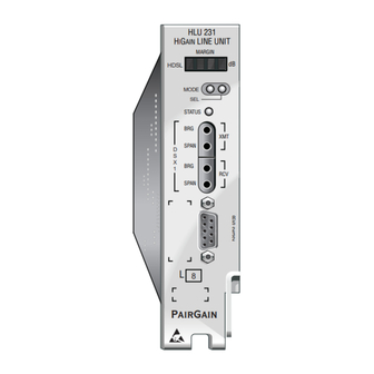
Figure 1. HLU-611 Front Panel. The PairGain HLU-611
is the Central Office side of a single pair repeaterless T1
transmission system.
SECTION 150-611-100
Revision 02
September 8, 1995
U
INE
NIT
Page 1
Advertisement
Table of Contents

Related Manuals for PairGain HIGAIN-2 HLU-611


Summary of Contents for PairGain HIGAIN-2 HLU-611
-
Page 1: Table Of Contents
10. INSTALLATION 11. TESTING CAUTION This product incorporates static sensitive components. Proper electrostatic discharge procedures must be followed. Figure 1. HLU-611 Front Panel. The PairGain HLU-611 is the Central Office side of a single pair repeaterless T1 transmission system. Page 1... -
Page 2: Product Overview
• DS1 LOS detector (125 consecutive 1. DESCRIPTION AND FEATURES zeros) 1.01 PairGain’s HiGain-2 Line Unit Model HLU- • Margin threshold alarm 611 Issue 1, List 1 (Figure 1), is the Central • Smart-Jack AIS option Office side of a single pair repeaterless T1 transmission system. -
Page 3: Specifications
PairGain representative will void the warranty. Span Voltage -170 Vdc maximum. 5.03 If a unit needs repair, call PairGain for a Margin Indicator Return Material Authorization (RMA) number and return the defective unit, freight prepaid, Displays span SNR margin for both spans relative... -
Page 4: Technical Assistance
A block diagram of the HLU-611 is shown in request for technical assistance is handled by an on- Figure 2. The HiGain-2 HLU-611 receives a duty Customer Service Engineer through a callback 1.544 Mbps DS1 data stream from the DSX-1 digital process. - Page 5 Section 150-611-100 Revision 02 7.03 The HLU-611 contains a demultiplexer that 7.09 The HLU-611 contains two separate power generates a 1.568 kbps data stream. The converters. The main power supply data stream contains VHDSL frames that are converts -48 V local battery to logic power for the HLU-611 circuits.
- Page 6 Section 150-611-100 Revision 02 7.12 7.17 The normally open alarm contacts available In Central Office locations, the maximum power dissipation for open faced, natural across pins 20 and 21 comprise the HLU- convection cooled mountings is limited to 120 W / 611’s Minor Alarm output.
-
Page 7: Options
Section 150-611-100 Revision 02 The HLU 611’s STATUS LED flashes RED for the can be terminated and the next loopback option duration of a minor alarm condition. Alarms 4 and 5 presented by depressing the MODE button. If can be inhibited by selecting NONE for the ESAL neither button is depressed for a period of 30 seconds, this manual loopback session terminates system option. - Page 8 Section 150-611-100 Revision 02 returns to its normal mode, without installing any occur at the DS1 output of the HLU. The HRU’s new changes, if neither button is depressed for 30 DS1 output will not be blocked. Also, all blocked seconds.
-
Page 9: Loopbacks
A3LB supports the additional 1 in 6 smart jack NLOC and NREM are issued from the HLU DS1 loopback command. Refer to the PairGain HiGain-2 interface. CLOC and CREM are issued from the Intelligent Repeater Application Note # 910 Part # HRU DS1 interface. -
Page 10: Installation And Test
Also, verify that the pre-equalizer is Kentrox T-Term, Wescom 342-30 shelves, or properly set. All installations should be set to the PairGain HLS-410 (19”) or HLS-419 (23”). The largest value that does not exceed the distance from HLU-611 slot pin-outs are shown in Figure 4. - Page 11 Section 150-611-100 Revision 02 11.04 The transmit and receive T1 DSX-1 ports show the performance data and alarm history have splitting access and bridging miniature screens. All the performance data shown in Figures 210 jacks as shown in Figure 2. Connecting one 8, 11 and 12 can be cleared to zero by selecting the (C)lear option from the HLU Status Screen shown in cable between the two BDG jacks and another...
- Page 12 Section 150-611-100 Revision 02 TABLE 2. SYSTEM OPTION SETTINGS MODE CHOICE DESCRIPTION EXT* Replaces the internal equalizer with a 12 Vpk-pk drive source for an external equalizer. Sets the Equalizer to DSX-1 for 0-133 feet. Sets the Equalizer to DSX-1 for 133-266 feet. Sets the Equalizer to DSX-1 for 266-399 feet.
- Page 13 Section 150-611-100 Revision 02 TABLE 2. SYSTEM OPTION SETTINGS (CONTINUED) MODE CHOICE DESCRIPTION DIS* Opens the minor alarm relay contacts if closed, and prevents another relay alarm closure from occurring. Enables activation of the minor alarm relay when a minor alarm condition occurs. AUTO The HLU-611 and HRU-612 independently monitor their incoming DS1 bit streams for the Binary Eight Zero Substitution (B8ZS) pattern.
- Page 14 Section 150-611-100 Revision 02 TABLE 3. HLU-611 TEST PROCEDURES FOR GNLB OPTION Step Action Have the C.O. tester send the HRU (3 in 7) in-band loop-up code for five seconds. Observe that the HLU displays the “NREM” message indicating an HRU loopback is in effect (see Figure 5). Have the C.O.
- Page 15 Section 150-611-100 Revision 02 TABLE 4. HLU-611 TEST PROCEDURES FOR A1LB OPTION Step Action Send into the HLU the inband ARMING and NIU (Network Interface Hit) LPBK code 11000 for at least five seconds, or at least four repetitions of the 16 bit ESF Data Link ARMING code 0001 0010 1111 1111.
- Page 16 Section 150-611-100 Revision 02 TABLE 4. HLU-611 TEST PROCEDURES FOR A1LB OPTION (CONTINUED) Step Action Using the following codes, a network tester can activate loopbacks NLOC or NREM or SMJK (if enabled) shown in Figure 5. A customer tester can activate loopbacks CLOC or CREM. Addressable 1 (A1LB) Repeater Loopback Commands ARMING or NIU LPBK (inband) Arming code...
- Page 17 Section 150-611-100 Revision 02 TABLE 5. HLU-611 TEST PROCEDURES FOR A2LB OPTION Step Action Send into the HLU the inband ARMING and NIU (Network Interface Hit) LPBK code 11000 for at least five seconds, or at least four repetitions of the 16 bit ESF Data Link ARMING code 0001 0010 1111 1111.
- Page 18 Section 150-611-100 Revision 02 TABLE 5. HLU-611 TEST PROCEDURES FOR A2LB OPTION (CONTINUED) Step Action Using the following codes, a network tester can activate loopbacks NLOC or NREM or SMJK (if enabled) shown in Figure 5. A customer tester can activate loopbacks CLOC or CREM. Addressable 2 (A2LB) Repeater Loopback Commands ARMING or NIU LPBK (inband) Arming code...
- Page 19 Section 150-611-100 Revision 02 TABLE 6. HLU-611 TEST PROCEDURES FOR A3LB OPTION Step Action The HiGain-2 Line Hit can be looped back (NLOC in Figure 5) by sending the (Addressable Office Repeater) LPBK activation code 1111(F) 1111(F) 0001(1) 1110(E) for at least five seconds. This causes the HLU to enter its NLOC state shown in Figure 5.
- Page 20 Section 150-611-100 Revision 02 TABLE 7. HLU-611 TEST PROCEDURES FOR A4LB OPTION Step Action The HiGain-2 Line Hit can be looped back (NLOC in Figure 5) by sending the (Addressable Office Repeater) LPBK activation code 1111(F) 1111(F) 0001(1) 1110(E) for at least five seconds. This causes the HLU to enter its NLOC state shown in Figure 5.
- Page 21 Section 150-611-100 Revision 02 TABLE 8. HLU-611 TEST PROCEDURES FOR A5LB OPTION Step Action Send into the HLU the inband ARMING and NIU (Network Interface Hit) LPBK code 11000 for at least five seconds, or at least four repetitions of the 16 bit ESF Data Link ARMING code 0001 0010 1111 1111.
- Page 22 Section 150-611-100 Revision 02 TABLE 8. HLU-611 TEST PROCEDURES FOR A5LB OPTION (CONTINUED) Step Action Using the following codes, a network tester can activate loopbacks NLOC or NREM or SMJK (if enabled) shown in Figure 5. A customer tester can activate loopbacks CLOC or CREM. Addressable 5 (A5LB) Repeater Loopback Commands ARMING or NIU LPBK (inband) Arming code...
- Page 23 Section 150-611-100 Revision 02 TABLE 9. HLU 4 CHARACTER FRONT PANEL MESSAGES Message Full Name Description CREM Customer Remote Loopback Signal from customer is looped back to customer at HLU-611. NLOC Network Local Loopback DSX signal is looped back to DSX at HLU. CLOC Customer Local Loopback Signal from Customer is looped back to customer at HRU-612.
- Page 24 Section 150-611-100 Revision 02 TABLE 9. HLU 4 CHARACTER FRONT PANEL MESSAGES (CONTINUED) Message Full Name Description PWR FEED Power Feed Short Indicates a short across the VHDSL pair. This same SHRT message can occur with an HRU that is drawing the correct amount of power over good cable pairs, but can’t communicate with the HRU.
- Page 25 Section 150-611-100 Revision 02 TABLE 10. HLU-611 STATUS MENU DEFINITIONS Message Full Name Description ALARMS NONE No Alarms LLOS Local Loss of Signal No signal from local T1 interface. RLOS Remote Loss of No signal from remote T1 interface. Signal LOSW Loss of Sync Word The VHDSL’s loop has lost sync.
- Page 26 Section 150-611-100 Revision 02 Figure 6. HLU-611 Main Menu. Figure 7. HLU Status Display. Page 26...
- Page 27 Section 150-611-100 Revision 02 Figure 8. Set Clock Menu. Figure 9. System Settings Menu. Page 27...
- Page 28 Section 150-611-100 Revision 02 FIGURE 10. Performance Data. Figure 11. Performance Data History. Page 28...
- Page 29 Section 150-611-100 Revision 02 Figure 12. HLU Alarm History. Copyright © 1995, PairGain Technologies, Inc. PairGain is a registered trademark, CopperOptics and HiGain-2 are trademarks of PairGain Technologies, Inc. Page 29...
Need help?
Do you have a question about the HIGAIN-2 HLU-611 and is the answer not in the manual?
Questions and answers