Table of Contents
Advertisement
Quick Links
Advertisement
Table of Contents

Related Manuals for Symbol LS 4071


Summary of Contents for Symbol LS 4071
- Page 1 LS 4071 Product Reference Guide...
- Page 2 LS 4071 Product Reference Guide 70-19303-02 Revision A — December 1999 Symbol Technologies, Inc. One Symbol Plaza, Holtsville N.Y. 11742...
- Page 3 LS 4071 Product Reference Guide 70-19303-02 Revision A December 1999...
- Page 4 (licensed program). Except as noted below, such license may not be assigned, sublicensed, or otherwise transferred by the user without prior written consent of Symbol. No right to copy a licensed program in whole or in part is granted, except as permitted under copyright law.
-
Page 5: Table Of Contents
Symbol Support Centers ........ - Page 6 Required Accessories............4-7 Optional Accessories .
- Page 7 Buffer Data ..............5-48 Clear Transmission Buffer .
- Page 8 Appendix A. UCC/EAN-128 ..............A-2 AIM Code Identifiers.
-
Page 9: About This Manual
Call the Support Center from a phone near the scanning equipment so that the service person can try to talk you through your problem. If the equipment is found to be working properly and the problem is symbol readability, the Support Center will request samples of your bar codes for analysis at our plant. -
Page 10: Symbol Support Centers
If the original shipping container was not kept, contact Symbol to have another sent to you. Symbol Support Centers For service information, warranty information or technical assistance contact or call the Symbol Support Center in: United States Canada Symbol Technologies, Inc. - Page 11 92184 Antony Cedex, France +358 9 5407 580 (Outside Finland) 01-40-96-52-21 (Inside France) +33-1-40-96-52-50 (Outside France) Germany Italy Symbol Technologies GmbH Symbol Technologies Italia S.R.L. Waldstrasse 68 Via Cristoforo Columbo, 49 D-63128 Dietzenbach, Germany 20090 Trezzano S/N Navigilo 6074-49020 (Inside Germany) Milano, Italy...
- Page 12 It shall not apply to any product (i) which has been repaired or altered unless done or approved by Symbol, (ii) which has not been maintained in accordance with any operating or handling instructions supplied by Symbol, (iii) which has been subjected to unusual physical or electrical stress, misuse, abuse, power shortage, negligence or accident or (iv) which has been used other than in accordance with the product operating and handling instructions.
-
Page 13: Warranty Coverage And Procedure
North America. Shipments from the US or other locations will be made F.O.B. Symbol’s manufacturing plant. Symbol will use new or refurbished parts at its discretion and will own all parts removed from repaired products. Customer will pay for the replacement product in case it does not return the replaced product to Symbol within 3 days of receipt of the replacement product. - Page 14 LS 4071 Product Reference Guide...
-
Page 15: Chapter 1 The Ls 4071 Scanner
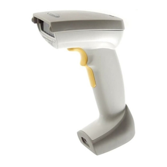
Chapter 1 The LS 4071 Scanner Scanning Made Easy The LS 4071 scanner lets you scan a bar code and transmit the data to a base station up to 10 feet (3 meters) away, without a physical cable to limit your movement. -
Page 16: Rechargeable Battery Pack
12-hour shift. When fully depleted, the battery pack can be recharged to full charge within 2 hours, with the LS 4071 inserted into the RL 47X base station. Alternatively, the battery module can be recharged in the Universal Four-Slot Charger/... -
Page 17: The Base Station
The LS 4071 Scanner The Base Station The base station receives scan data from the scanner via an RF transmission and acknowledges receipt with an audible beep. It then transmits that data to the host device through an attached cable. It also acts as a holder for the scanner. - Page 18 LS 4071 Product Reference Guide...
-
Page 19: Chapter 2 Set Up
Remove the scanner from its packing and inspect it for damage. If the scanner was damaged in transit, call the Symbol Support Center at one of the telephone numbers listed on page viii. KEEP THE PACKING. It is the approved shipping container and should be used if you ever need to return your equipment for servicing. - Page 20 LS 4071 Product Reference Guide 4. The Synapse adapter cables have a flying power lead. Connect this lead to the receptacle in the Synapse cable, as shown below. See the Synapse guide for details. Synapse Adapter Cable Flying Power Lead Figure 2-2.
-
Page 21: Charging The Battery
Set Up Charging the Battery Before its first use, the LS 4071 batteries must be charged. To do so: 1. Connect the power supply to the power input jack on the RL 47X base station. 2. Connect the power supply to a receptacle supplying AC power of the proper voltage level. -
Page 22: Battery Life
As they begin to age, batteries do not hold a charge as long as when they were fresh; you have to charge them more often. New battery packs can be obtained from Symbol Technologies. See your Symbol representative for more information. -
Page 23: Connecting To A Host
Set Up Connecting to a Host With some terminal types, the LS 4071 is unable to answer host terminal polls until the appropriate host type is selected. This may result in an error message generated by the host. To correct this situation, select the proper parameter set and initialize the host terminal. - Page 24 LS 4071 Product Reference Guide IBM 468X/9X (Contd) PORT 5B PORT 9B PORT 17 Figure 2-5. IBM 4683 Rear Panel With Cover Removed Figure 2-6. IBM 4684 Rear Panel With Cover Removed...
-
Page 25: Wand Emulation, Ocia, Ocr, Keyboard Wedges
Set Up IBM 468X/9X (Contd) Figure 2-7. IBM 4693 Rear Panel With Cover Removed PORT 9E Figure 2-8. IBM 4694 Rear Panel With Cover Removed Wand Emulation, OCIA, OCR, Keyboard Wedges See the instructions packed with the appropriate Synapse cable. Adapter cable required. - Page 26 LS 4071 Product Reference Guide...
-
Page 27: Chapter 3 Scanning
3.0 seconds (default). 3. Scan Make sure the symbol you want to scan is within the scanning range. See the LS 4071 Decode Zone diagram on page 3-4. The scanner has read the symbol when: The yellow LED on the rear of the scanner turns green for a short period •... -
Page 28: Aiming
LS 4071 Product Reference Guide Aiming Scan the Entire Symbol Your scan beam must cross every bar and space on the symbol. • The larger the symbol, the farther away you should hold the scanner. • Hold the scanner closer for symbols with bars that are close together. -
Page 29: Hold At An Angle
Scanning Hold at an Angle Do not hold the scanner directly over the bar code. Laser light reflecting directly back into the scanner from the bar code is known as specular reflection. This strong light can “blind” the scanner and make decoding difficult. The area where specular reflection occurs is known as a “dead zone.”... -
Page 30: Ls 4071 Decode Zone
40 Mil Minimum Element 38.1 55 Mil Minimum Element Width 12.7 25.4 38.1 50.8 63.5 76.2 88.9 101.6 114. Depth of Field in Inches / Centimeters Depth of field as a function of minimum element width. Figure 3-2. LS 4071 Decode Zone... -
Page 31: What If
• Make sure the device is programmed to read the type of bar code you • want to scan. Check the symbol to make sure it is not defaced. • Try scanning similar symbols of the same code type. •... -
Page 32: Programming The System
Note: If after performing these checks the symbol still does not scan, contact your distributor or call the Symbol Support Center. See page viii for the telephone number. Programming the System An LS 4071 is programmed by scanning sequences of bar codes; see Chapter 5. -
Page 33: Chapter 4 Maintenance And Specifications
Chapter 4 Maintenance and Specifications Maintenance Do not allow any abrasive material to touch the scanner window. • Remove any dirt particles with a damp cloth. • Wipe the scanner window using a damp cloth, and if necessary, a non- •... -
Page 34: Changing Battery Packs
LS 4071 Product Reference Guide Changing Battery Packs Once a battery is fully charged, it will generally last up to 12 hours without being returned to the base. By returning it to the base during the day, you extend this time. -
Page 35: To Change A Battery Pack
Maintenance and Specifications To Change a Battery Pack: 1. Remove boot from lower handle of scanner. Gently pull the boot from the back of the scanner. Avoid using sharp objects, as they might damage the boot. Slide the back of the boot off the scanner and remove by pushing forward. - Page 36 LS 4071 Product Reference Guide 3. Remove battery pack. Remove the battery pack from its compartment. Disconnect it from the scanner. Do not remove the wire harness. Disconnect here Wire harness Figure 4-4. Removing the Battery Pack 4. Install new battery pack.
- Page 37 Maintenance and Specifications 5. Install battery pack cover. Place the cover on the bottom of the scanner and gently push forward until it engages (snaps into place). To Replace Figure 4-5. Replacing the Battery Cover 6. Re-install boot. Slide boot onto the front of the base of the scanner. Be sure the charging contacts are visible through the front of the boot.
-
Page 38: Charge Status Led Indications
LS 4071 Product Reference Guide Charge Status LED Indications On the base station, there is a yellow LED indicator which uses flashing patterns to display the charger status, as shown in the table below. Table 4-1. Charge Status LED Indications... -
Page 39: Accessories
Maintenance and Specifications Accessories Required Accessories LS 4071 scanners are sent as a package with required accessories, listed in the Product Ordering Guide. Optional accessories are available at extra cost. Optional Accessories Optional accessories, listed in the Product Ordering Guide, include various stands and holders, which are supplied at extra cost. -
Page 40: Technical Specifications
Full ASCII, Trioptic Code 39, Code 93, Codabar, Interleaved 2 of 5, Code 128, EAN 128, Discrete 2 of 5, and MSI Plessey. Set code length(s) for any linear code type. The LS 4071 can auto- discriminate between all of the above code types except for Code 39 and Code 39 Full ASCII. - Page 41 Maintenance and Specifications Table 4-2. (Continued)Technical Specifications Item Description Operating Temperature 32° to 104°F 0° to 40°C Storage Temperature -40° to 140°F -40° to 60°C Humidity 5% to 95% (non-condensing) Durability (Scanner) 4-ft. drop to concrete 1.2 m Dimensions See figure below Laser Classifications CDRH Class II IEC Class 1...
-
Page 42: Base Pin Outs
LS 4071 Product Reference Guide Base Pin Outs The following table shows the pin outs for each base station. Table 4-3. Pin Outs RL474 RL475 Reserved Reserved Power Out Power Out Ground Ground Synapse Data Synapse Data Synapse Clock Synapse Clock... -
Page 43: Beeper Indications
4 Beeps - long low tone Base A transmission error has been detected in a scanned symbol. The data is ignored. This occurs if a unit is not properly configured. Check option settings. 5 Beeps - low tone Base Convert or format error. - Page 44 LS 4071 Product Reference Guide Table 4-4. (Continued) Beeper Indications Code 39 Buffering Hi/lo tone Scanner New Code 39 data was entered into the buffer. 3 Beeps - long high tone Scanner Code 39 buffer is full. Lo/hi/lo tone Scanner The buffer was erased, or there was an attempt to transmit an empty buffer.
-
Page 45: Chapter 5 Parameter Menus
Chapter 5 Parameter Menus Operational Parameters The LS 4071 is shipped with the default settings beginning on page 5-2. These default values are stored in non-volatile memory and are preserved even when the scanner is powered down. You can change these default values by scanning the appropriate bar codes included in this manual. - Page 46 LS 4071 Product Reference Guide The following table lists the defaults for all parameters. If you wish to change any option, scan the appropriate bar code(s). Table 5-1. Default Table Parameter Default Page Number Set Default Parameter All Defaults Host Type...
- Page 47 Parameter Menus Table 5-1. Default Table Parameter Default Page Number Transmit UPC-A Check Digit Enable 5-28 Transmit UPC-E Check Digit Enable 5-28 UPC-A Preamble System Character 5-29 UPC-E Preamble System Character 5-30 Convert UPC-E to A Disable 5-31 EAN-8 Zero Extend Disable 5-32 Convert EAN-8 to EAN-13 Type...
- Page 48 LS 4071 Product Reference Guide Table 5-1. Default Table Parameter Default Page Number Code 93 Code 93 Disable 5-51 Set Length(s) for Code 93 4-55 5-52 Interleaved 2 of 5 Interleaved 2 of 5 Enable 5-54 Set Length(s) for I 2 of 5...
- Page 49 Parameter Menus Table 5-1. Default Table Parameter Default Page Number MSI Plessey MSI Plessey Disable 5-68 Set Length(s) for MSI Plessey Any Length 5-70 MSI Plessey Check Digits 5-71 Transmit MSI Plessey Check Digit Disable 5-72 MSI Plessey Check Digit Algorithm Mod 10/Mod 10 5-73 Data Options...
- Page 50 LS 4071 Product Reference Guide Table 5-1. Default Table Parameter Default Page Number RS-232C RS-232 Host Type Standard 5-11 Baud Rate 9600 5-82 Parity None 5-83 Check Receive Errors Disable 5-85 Hardware Handshaking None 5-87 Software Handshaking None 5-89 Host Serial Response Time-out 2 Sec.
-
Page 51: Set Default Parameter
Parameter Menus Set Default Parameter Scanning this bar code returns all parameters to the values listed in the default table beginning on page 5-2. SET ALL DEFAULTS... -
Page 52: Host Type
LS 4071 Product Reference Guide Host Type IBM 46XX Host Types To select one of the following as a POS Interface, scan the appropriate bar code below. Note: To properly communicate with 468X/9X terminals, the driver corresponding to the port being used must be loaded and enabled when you are configuring your terminal system. -
Page 53: Rs-232C Host Types
Parameter Menus Host Type RS-232C Host Types Three RS-232C hosts are set up with their own parameter default settings. Selecting the ICL, Fujitsu or Nixdorf RS-232C terminal sets the defaults listed below. These defaults take precedence over Standard RS-232 defaults. So, if you’ve selected Fujitsu RS-232C, then select the Standard RS-232 defaults, the Fujitsu defaults still take precedence. - Page 54 LS 4071 Product Reference Guide Host Type RS-232C Host Types Selecting the ICL, Fujitsu, or Nixdorf RS-232C terminal enables the transmission of Code ID Characters as listed below. These Code ID Characters are not programmable and are separate from the Transmit Code ID feature. The Transmit Code ID feature should not be enabled for these terminals.
- Page 55 Parameter Menus Host Type RS-232C Host Types To select an RS-232C Host Interface, scan one of the following bar codes. STANDARD RS-232C ICL RS-232C NIXDORF RS-232C Mode A NIXDORF RS-232C Mode B FUJITSU RS-232C 5-11...
-
Page 56: Beeper Tone
LS 4071 Product Reference Guide Beeper Tone To select a decode beep frequency (tone), scan the LOW FREQUENCY, MEDIUM FREQUENCY, or HIGH FREQUENCY bar code. LOW FREQUENCY MEDIUM FREQUENCY HIGH FREQUENCY 5-12... -
Page 57: Beeper Volume
Parameter Menus Beeper Volume To select a beeper volume, scan the LOW VOLUME, MEDIUM VOLUME, or HIGH VOLUME bar code. This selection affects the scanner beeper, base beeper, or both if so selected. LOW VOLUME MEDIUM VOLUME HIGH VOLUME 5-13... -
Page 58: Laser On Time
LS 4071 Product Reference Guide Laser On Time This parameter sets the maximum time decode processing continues during a scan attempt. It is programmable in 0.1 second increments from 0.5 to 9.9 seconds. To set a Laser On Time, scan the bar code below. Next scan two numeric bar codes beginning on page 5-98 that correspond to the desired time on. -
Page 59: Base Beep After Good Decode
BASE BEEP AFTER GOOD DECODE Do Not Beep After Good Decode Scan this symbol if you do not want the base unit to beep after a good decode. The beeper still operates during parameter menu scanning and indicates error conditions. -
Page 60: Scanner Beep After Good Decode
Scan this symbol if you want the scanner to beep after a good decode. SCANNER BEEP AFTER GOOD DECODE Do Not Beep After Good Decode Scan this symbol if you want the scanner not to beep after a good decode. The beeper still operates during parameter menu scanning and indicates error conditions. -
Page 61: Base Beep Type
Parameter Menus Base Beep Type Select the type of beep for the base unit. This parameter is useful when two or more systems are installed in proximity to each other. Unique beep patterns can be set up to distinguish each system’s receipt of bar code data. Beep 1 Beep 2 Beep 3... -
Page 62: Transmit "No Read" Message
When enabled, if a symbol does not decode, “NR” is transmitted. Any prefixes or suffixes which have been enabled are appended around this message. ENABLE NO READ Do Not Transmit “No Read” Message When disabled, if a symbol does not read, nothing is sent to the host. DISABLE NO READ 5-18... -
Page 63: Linear Code Type Security Level
Linear Code Type Security Level (Does not apply to Code 128) The LS 4071 offers four levels of decode security for linear code types (e.g. Code 39, Interleaved 2 of 5). Higher security levels are selected for decreasing levels of bar code quality. As security levels increase, the scanner’s aggressiveness decreases. - Page 64 LS 4071 Product Reference Guide Linear Code Type Security Level (Cont’d) Linear Security Level 2 The following code types must be successfully read twice before being decoded: Code Type Length LINEAR SECURITY LEVEL 2 Linear Security Level 3 Code types other than the following must be successfully read twice before being decoded.
- Page 65 Parameter Menus Linear Code Type Security Level (Cont’d) Linear Security Level 4 The following code types must be successfully read three times before being decoded: Code Type Length LINEAR SECURITY LEVEL 4 5-21...
-
Page 66: Bi-Directional Redundancy
LS 4071 Product Reference Guide Bi-directional Redundancy This parameter is only valid when a Linear Code Type Security Level (see page 5-19) is enabled. When this parameter is enabled, a bar code must be successfully scanned in both directions (forward and reverse) before being decoded. -
Page 67: Enable/Disable Upc-E/Upc-A
Parameter Menus Enable/Disable UPC-E/UPC-A To enable or disable UPC-E or UPC-A, scan the appropriate bar code below. ENABLE UPC-E DISABLE UPC-E ENABLE UPC-A DISABLE UPC-A 5-23... -
Page 68: Enable/Disable Ean-8/Ean-13
LS 4071 Product Reference Guide Enable/Disable EAN-8/EAN-13 To enable or disable EAN-8 or EAN-13, scan the appropriate bar code below. ENABLE EAN-8 DISABLE EAN-8 ENABLE EAN-13 DISABLE EAN-13 5-24... -
Page 69: Enable/Disable Bookland Ean
Parameter Menus Enable/Disable Bookland EAN To enable or disable EAN Bookland, scan the appropriate bar code below. ENABLE BOOKLAND EAN DISABLE BOOKLAND EAN 5-25... -
Page 70: Decode Upc/Ean Supplementals
If UPC/EAN without supplemental characters is selected, and the • LS 4071 is presented with a UPC/EAN plus supplemental symbol, the UPC/EAN is decoded and the supplemental characters ignored. An autodiscriminate option is also available. If this option is selected, •... -
Page 71: Decode Upc/Ean Supplemental Redundancy
Decode UPC/EAN Supplemental Redundancy With Autodiscriminate UPC/EAN Supplementals selected, this option adjusts the number of times a symbol without supplementals is decoded before transmission. The range is from two to 20 times. Five or above is recommended when decoding a mix of UPC/EAN symbols with and without supplementals, and the autodiscriminate option is selected. -
Page 72: Transmit Upc-A/Upc-E Check Digit
LS 4071 Product Reference Guide Transmit UPC-A/UPC-E Check Digit Scan the appropriate bar code below to transmit the symbol with or without the UPC-A or UPC-E check digit. TRANSMIT UPC-A CHECK DIGIT DO NOT TRANSMIT UPC-A CHECK DIGIT TRANSMIT UPC-E CHECK DIGIT... -
Page 73: Upc-A Preamble
Three options are given for lead-in characters for UPC-A symbols transmitted to the host device: transmit system character only, transmit system character and country code (“0” for USA), and no preamble transmitted. The lead-in characters are considered part of the symbol. NO PREAMBLE (<DATA>) SYSTEM CHARACTER (<SYSTEM CHARACTER>... -
Page 74: Upc-E Preamble
Three options are given for lead-in characters for UPC-E symbols transmitted to the host device: transmit system character only, transmit system character and country code (“0” for USA), and no preamble transmitted. The lead-in characters are considered part of the symbol. NO PREAMBLE (<DATA>) SYSTEM CHARACTER (<SYSTEM CHARACTER>... -
Page 75: Convert Upc-E To Upc-A
Parameter Menus Convert UPC-E to UPC-A This parameter converts UPC-E (zero suppressed) decoded data to UPC-A format before transmission. After conversion, data will follow UPC-A format and be affected by UPC-A programming selections (e.g., Preamble, Check Digit). Scanning DO NOT CONVERT UPC-E TO UPC-A allows you to transmit UPC-E (zero suppressed) decoded data. -
Page 76: Ean Zero Extend
LS 4071 Product Reference Guide EAN Zero Extend If this parameter is enabled, five leading zeros are added to decoded EAN-8 symbols to make them compatible in format to EAN-13 symbols. Disabling this parameter returns EAN-8 symbols to their normal format. -
Page 77: Convert Ean-8 To Ean-13 Type
Convert EAN-8 to EAN-13 Type When EAN Zero Extend is enabled, this parameter gives you the option of labeling the extended symbol as either an EAN-13 bar code, or an EAN-8 bar code. When EAN Zero Extend is disabled, this parameter has no effect on bar code data. -
Page 78: Upc/Ean Security Level
LS 4071 Product Reference Guide UPC/EAN Security Level The LS 4071 offers four levels of decode security for UPC/EAN bar codes. Increasing levels of security are provided for decreasing levels of bar code quality. There is an inverse relationship between security and scanner aggressiveness, so be sure to choose only that level of security necessary for any given application. - Page 79 Parameter Menus UPC/EAN Security Level (Cont’d) UPC/EAN Security Level 2 If you are experiencing mis-decodes of poorly printed bar codes, and the mis- decodes are not limited to characters 1, 2, 7, and 8, select this security level. UPC/EAN SECURITY LEVEL 2 UPC/EAN Security Level 3 If you have tried Security Level 2, and are still experiencing misdecodes, select this security level.
-
Page 80: Upc/Ean Coupon Code
LS 4071 Product Reference Guide UPC/EAN Coupon Code When enabled, this parameter will decode UPC-A, UPC-A with 2 supplemental characters, UPC-A with 5 supplemental characters, and UPC-A/ EAN128 bar codes. UPC-A with supplemental characters need not be enabled. ENABLE UPC/EAN COUPON CODE... -
Page 81: Enable/Disable Code 128
Parameter Menus Enable/Disable Code 128 To enable or disable Code 128, scan the appropriate bar code below. ENABLE CODE 128 DISABLE CODE 128 5-37... -
Page 82: Enable/Disable Ucc/Ean-128
LS 4071 Product Reference Guide Enable/Disable UCC/EAN-128 To enable or disable UCC/EAN-128, scan the appropriate bar code below. (See Appendix A for details on UCC/EAN-128.) ENABLE UCC/EAN-128 DISABLE UCC/EAN-128 5-38... -
Page 83: Lengths For Code 128
Parameter Menus Lengths for Code 128 No length setting is required for Code 128. The default setting is Any Length. 5-39... -
Page 84: Enable/Disable Code 39
LS 4071 Product Reference Guide Enable/Disable Code 39 To enable or disable Code 39, scan the appropriate bar code below. ENABLE CODE 39 DISABLE CODE 39 5-40... -
Page 85: Enable/Disable Trioptic Code 39
Parameter Menus Enable/Disable Trioptic Code 39 Trioptic Code 39 symbols always contain six characters. Trioptic Code 39 and Code 39 Full ASCII cannot be enabled simultaneously. If you get an error beep when enabling Trioptic Code 39, disable Code 39 Full ASCII and try again. To enable or disable Trioptic Code 39, scan the appropriate bar code below. - Page 86 LS 4071 Product Reference Guide Set Lengths for Code 39 Lengths for Code 39 may be set for any length, one or two discrete lengths, or lengths within a specific range. The length of a code refers to the number of characters (i.e., human readable characters), including check digit(s) the code...
-
Page 87: Set Lengths For Code 39
Parameter Menus Set Lengths for Code 39 (Cont’d) Length Within Range - This option allows you to decode a code type within a specified range. For example to decode Code 39 symbols containing between 4 and 12 characters, first scan Code 39 Length Within Range. -
Page 88: Code 39 Check Digit Verification
LS 4071 Product Reference Guide Code 39 Check Digit Verification When enabled, this parameter checks the integrity of a Code 39 symbol to ensure it complies with specified algorithms. Only those code 39 symbols which include a modulo 43 check digit are decoded when this parameter is enabled. -
Page 89: Transmit Code 39 Check Digit
Parameter Menus Transmit Code 39 Check Digit Scan this symbol if you want to transmit the check digit with the data. TRANSMIT CODE 39 CHECK DIGIT (ENABLE) Do Not Transmit Code 39 Check Digit Scan this symbol if you want to transmit the data without the check digit. -
Page 90: Enable/Disable Code 39 Full Ascii
LS 4071 Product Reference Guide Enable/Disable Code 39 Full ASCII To enable or disable Code 39 Full ASCII, scan the appropriate bar code below. When enabled, the ASCII character set assigns a code to letters, punctuation marks, numerals, and most control keystrokes on the keyboard. -
Page 91: Code 39 Buffering (Scan & Store)
The leading space is not buffered. Decode of a valid Code 39 symbol with no leading space causes transmission in sequence of all buffered data in a first-in first-out format, plus transmission of the “triggering”... -
Page 92: Buffer Data
TRANSMIT BUFFER bar codes are length 1. Be sure Code 39 length is set to include length 1. Buffer Data To buffer data, Code 39 buffering must be enabled, and a symbol must be read with a space immediately following the start pattern. Unless symbol overflows the transmission buffer, the unit gives lo/hi •... -
Page 93: Transmit Buffer
No transmission occurs. Data in buffer is not affected. • Attempt to Transmit an Empty Buffer If the symbol just read was the transmit buffer symbol and the Code 39 buffer is empty: A short lo/hi/lo beep signals that the buffer is empty. -
Page 94: Convert Code 39 To Code 32
Note: Code 39 must be enabled in order for this parameter to function. Do Not Convert Code 39 to Code 32 Scan this symbol if you do not want to convert Code 39 to Code 32. DO NOT CONVERT CODE 39 TO CODE 32 (DISABLE) -
Page 95: Enable/Disable Code 93
Parameter Menus Enable/Disable Code 93 To enable or disable Code 93, scan the appropriate bar code below. ENABLE CODE 93 DISABLE CODE 93 5-51... - Page 96 LS 4071 Product Reference Guide Set Lengths for Code 93 Lengths for Code 93 may be set for any length, one or two discrete lengths, or lengths within a specific range. The length of a code refers to the number of characters (i.e., human readable characters), including check digit(s) the code...
-
Page 97: Set Lengths For Code 93
Parameter Menus Set Lengths for Code 93 (Cont’d) Length Within Range - This option allows you to decode a code type within a specified range. For example to decode Code 93 symbols containing between 4 and 12 characters, first scan Code 93 Length Within Range. -
Page 98: Enable/Disable Interleaved 2 Of 5
LS 4071 Product Reference Guide Enable/Disable Interleaved 2 of 5 To enable or disable Interleaved 2 of 5, scan the appropriate bar code below. ENABLE INTERLEAVED 2 OF 5 DISABLE INTERLEAVED 2 OF 5 5-54... - Page 99 Parameter Menus Set Lengths for Interleaved 2 of 5 Lengths for I 2 of 5 may be set for any length, one or two discrete lengths, or lengths within a specific range. The length of a code refers to the number of characters (i.e., human readable characters) the code contains and includes check digits.
-
Page 100: Set Lengths For Interleaved 2 Of 5
LS 4071 Product Reference Guide Set Lengths for Interleaved 2 of 5 (Cont’d) Length Within Range - This option allows you to decode a code type within a specified range. For example to decode I 2 of 5 symbols containing between 4 and 12 characters, first scan I 2 of 5 Length Within Range. -
Page 101: I 2 Of 5 Check Digit Verification
Parameter Menus I 2 of 5 Check Digit Verification When enabled, this parameter checks the integrity of an I 2 of 5 symbol to ensure it complies a specified algorithm, either USS (Uniform Symbology Specification), or OPCC (Optical Product Code Council). -
Page 102: Transmit I 2 Of 5 Check Digit
LS 4071 Product Reference Guide Transmit I 2 of 5 Check Digit Scan this symbol if you want to transmit the check digit with the data. TRANSMIT I 2 of 5 CHECK DIGIT (ENABLE) Do Not Transmit I 2 of 5 Check Digit Scan this symbol if you want to transmit the data without the check digit. -
Page 103: Convert I 2 Of 5 To Ean-13
Parameter Menus Convert I 2 of 5 to EAN-13 This parameter converts a 14 character I 2 of 5 code into EAN-13, and transmits to the host as EAN-13. In order to accomplish this, the I 2 of 5 code must be enabled, one length must be set to 14, and the code must have a leading zero and a valid EAN-13 check digit. -
Page 104: Enable/Disable Discrete 2 Of 5
LS 4071 Product Reference Guide Enable/Disable Discrete 2 of 5 To enable or disable Discrete 2 of 5, scan the appropriate bar code below. ENABLE DISCRETE 2 OF 5 DISABLE DISCRETE 2 OF 5 5-60... - Page 105 Parameter Menus Set Lengths for Discrete 2 of 5 Lengths for D 2 of 5 may be set for any length, one or two discrete lengths, or lengths within a specific range. The length of a code refers to the number of characters (i.e., human readable characters) the code contains, and includes check digits.
-
Page 106: Set Lengths For Discrete 2 Of 5
LS 4071 Product Reference Guide Set Lengths for Discrete 2 of 5 (Cont’d) Length Within Range - This option allows you to decode a code type within a specified range. For example to decode D 2 of 5 symbols containing between 4 and 12 characters, first scan D 2 of 5 Length Within Range. -
Page 107: Enable/Disable Codabar
Parameter Menus Enable/Disable Codabar To enable or disable Codabar, scan the appropriate bar code below. ENABLE CODABAR DISABLE CODABAR 5-63... -
Page 108: Set Lengths For Codabar
LS 4071 Product Reference Guide Set Lengths for Codabar Lengths for Codabar may be set for any length, one or two discrete lengths, or lengths within a specific range. The length of a code refers to the number of characters (i.e., human readable characters) the code contains. It also includes any start or stop characters. - Page 109 Parameter Menus Set Lengths for Codabar (Cont’d) Length Within Range - This option allows you to decode a code type within a specified range. For example to decode Codabar symbols containing between 4 and 12 characters, first scan Codabar Length Within Range. Then scan 0, 4, 1 and 2 (single digit numbers must always be preceded by a leading zero).
-
Page 110: Clsi Editing
If enabled, this parameter strips the start and stop characters and inserts a space after the first, fifth, and tenth characters of a 14-character Codabar symbol. Note: Symbol length does not include start and stop characters. ENABLE CLSI EDITING DISABLE CLSI EDITING... -
Page 111: Notis Editing
Parameter Menus NOTIS Editing If enabled, this parameter strips the start and stop characters from a decoded Codabar symbol. ENABLE NOTIS EDITING DISABLE NOTIS EDITING 5-67... -
Page 112: Enable/Disable Msi Plessey
LS 4071 Product Reference Guide Enable/Disable MSI Plessey To enable or disable MSI Plessey, scan the appropriate bar code below. ENABLE MSI PLESSEY DISABLE MSI PLESSEY 5-68... -
Page 113: Set Lengths For Msi Plessey
Parameter Menus Set Lengths for MSI Plessey Lengths for MSI Plessey may be set for any length, one or two discrete lengths, or lengths within a specific range. The length of a code refers to the number of characters (i.e., human readable characters) the code contains, and includes check digits. - Page 114 LS 4071 Product Reference Guide Set Lengths for MSI Plessey (Cont’d) Length Within Range - This option allows you to decode a code type within a specified range. For example to decode MSI Plessey symbols containing between 4 and 12 characters, first scan MSI Plessey Length Within Range.
-
Page 115: Msi Plessey Check Digits
Parameter Menus MSI Plessey Check Digits These check digits, at the end of the bar code verify the integrity of the data. At least one check digit is always required. Check digits are not automatically transmitted with the data. ONE MSI Plessey CHECK DIGIT TWO MSI Plessey CHECK DIGIT 5-71... -
Page 116: Transmit Msi Plessey Check Digit
LS 4071 Product Reference Guide Transmit MSI Plessey Check Digit Scan this symbol if you want to transmit the check digit with the data. TRANSMIT MSI Plessey CHECK DIGIT (ENABLE) Do Not Transmit MSI Plessey Check Digit Scan this symbol if you want to transmit the data without the check digit. -
Page 117: Msi Plessey Check Digit Algorithm
Parameter Menus MSI Plessey Check Digit Algorithm When the two MSI Plessey check digits option is selected, an additional verification is required to ensure integrity. Either of the two following algorithms may be selected. MOD 10/MOD 11 MOD 10/MOD 10 5-73... -
Page 118: Transmit Code Id Character
ID character is inserted between the prefix and the decoded symbol. The user may select no code ID character, a Symbol Code ID character, or an AIM Code ID character. The Symbol Code ID characters are listed below; see Appendix A for AIM Identifiers. - Page 119 Parameter Menus Transmit Code ID Character (Cont’d) SYMBOL CODE ID CHARACTER AIM CODE ID CHARACTER NONE 5-75...
-
Page 120: Pause Duration
LS 4071 Product Reference Guide Pause Duration This parameter allows a pause to be inserted at any point in the data transmission. Pauses are set by scanning a two digit number (i.e. two bar codes), and are measured in 1/10 second intervals. For example, scanning bar codes “0”... -
Page 121: Prefix/Suffix Values
Parameter Menus Prefix/Suffix Values A prefix/suffix may be appended to scan data for use in data editing. These values are set by scanning a four digit number (i.e. four bar codes) that corresponds to key codes for various terminals. See Appendix A for conversion tables. -
Page 122: Scan Data Transmission Format
LS 4071 Product Reference Guide Scan Data Transmission Format To change the Scan Data Transmission Format, scan the SCAN OPTIONS bar code below. Then select one of four options. When you have made your selection, scan the ENTER bar code on the next page. If you make a mistake, scan the DATA FORMAT CANCEL bar code on the next page. - Page 123 Parameter Menus Scan Data Transmission Format (Cont’d) <PREFIX> <DATA> <PREFIX> <DATA> <SUFFIX> ENTER DATA FORMAT CANCEL 5-79...
-
Page 124: Transmit Ascii/Intermediate Data
LS 4071 Product Reference Guide Transmit ASCII/Intermediate Data Intermediate data is required to communicate with Wand and Scanner Emulation synapse cables. All other configurations require ASCII data output (default). To select either option, scan the appropriate bar code below. ASCII DATA... -
Page 125: Rs-232C Parameters
Parameter Menus RS-232C Parameters Baud Rate Baud rate is the number of bits of data transmitted per second. The scanner's baud rate setting should match the data rate setting of the host device. If not, data may not reach the host device or may reach it in distorted form. BAUD RATE 300 BAUD RATE 600 BAUD RATE 1200... - Page 126 LS 4071 Product Reference Guide RS-232C Parameters Baud Rate BAUD RATE 4800 BAUD RATE 9600 BAUD RATE 19,200 5-82...
-
Page 127: Parity
Parameter Menus RS-232C Parameters Parity A parity check bit is the most significant bit of each ASCII coded character. Select the parity type according to host device requirements. If you select ODD parity, the parity bit has a value 0 or 1, based on data, to ensure than an odd number of 1 bits are contained in the coded character. - Page 128 LS 4071 Product Reference Guide RS-232C Parameters Parity Select MARK parity and the parity bit is always 1. MARK Select SPACE parity and the parity bit is always 0. SPACE If no parity is required, select NONE. NONE 5-84...
-
Page 129: Check Receive Errors
Parameter Menus RS-232C Parameters Check Receive Errors Select whether or not the parity, framing, and overrun of received characters are checked. The type of parity used is selectable through the PARITY parameter. CHECK FOR RECEIVED ERRORS DO NOT CHECK FOR RECEIVED ERRORS 5-85... -
Page 130: Hardware Handshaking
LS 4071 Product Reference Guide RS-232C Parameters Hardware Handshaking The data interface consists of an RS-232C port. The port has been designed to operate either with or without the hardware handshaking lines, RTS, Request to Send, and CTS, Clear to Send. - Page 131 Parameter Menus RS-232C Parameters Hardware Handshaking Scan the bar code below if no Hardware Handshaking is desired. NONE Scan the bar code below to select Standard RTS/CTS Hardware Handshaking. STANDARD RTS/CTS When RTS/CTS Option 1 is selected, the base asserts RTS before transmitting and ignores the state of CTS.
- Page 132 LS 4071 Product Reference Guide RS-232C Parameters Hardware Handshaking When Option 2 is selected, RTS is always high or low (user-programmed logic level). However, the base waits for CTS to be asserted before transmitting data. If CTS is not asserted within two seconds (default), the base issues an error indication and discards the data.
-
Page 133: Software Handshaking
Parameter Menus RS-232C Parameters Software Handshaking This parameter offers control of the data transmission process in addition to, or instead of, that offered by hardware handshaking. There are five options. If Software Handshaking and Hardware Handshaking are both enabled, Hardware Handshaking takes precedence. None When this option is selected, data is transmitted immediately. - Page 134 LS 4071 Product Reference Guide RS-232C Parameters Software Handshaking When this option is selected, the base waits for an ENQ character from the host before transmitting data. If an ENQ is not received within two seconds, the base issues an error indication and discards the data. The host must transmit an ENQ character at least every two seconds to prevent transmission errors.
- Page 135 Parameter Menus RS-232C Parameters Software Handshaking XON/XOFF An XOFF character turns the base transmission off until the base receives an XON character. There are two situations for XON/XOFF: XOFF is received before the base has data to send. When the base has data •...
-
Page 136: Host Serial Response Time-Out
LS 4071 Product Reference Guide RS-232C Parameters Host Serial Response Time-out This parameter specifies how long the base waits for an ACK, NAK or CTS before determining that a transmission error has occurred. This only applies when in one of the ACK/NAK Software Handshaking modes, or RTS/CTS Hardware Handshaking option. -
Page 137: Rts Line State
Parameter Menus RS-232C Parameters RTS Line State This parameter is used to set the idle state of the Serial Host RTS line. To select LOW RTS line state, scan the bar code below. HOST: LOW RTS To select HIGH RTS line state, scan the bar code below. HOST: HIGH RTS 5-93... -
Page 138: Stop Bit Select
LS 4071 Product Reference Guide RS-232C Parameters Stop Bit Select The stop bit(s) at the end of each transmitted character marks the end of transmission of one character and prepares the receiving device for the next character in the serial data stream. The number of stop bits (one or two) selected depends on the number the receiving terminal is programmed to accommodate. -
Page 139: Ascii Format
Parameter Menus RS-232C Parameters ASCII Format This parameter allows the base to interface with devices requiring a 7-bit or 8- bit ASCII protocol. 7-BIT 8-BIT 5-95... -
Page 140: Beep On
LS 4071 Product Reference Guide RS-232C Parameters Beep on <BEL> When this parameter is enabled, the base issues a beep when a <BEL> character is detected on the RS-232C serial line. <BEL> is issued to gain a user's attention to indicate an illegal entry or other important event. -
Page 141: Intercharacter Delay
Parameter Menus RS-232C Parameters Intercharacter Delay Select the intercharacter delay option matching host requirements. The intercharacter delay gives the host system time to service its receiver and perform other tasks between characters. The delay period can range from no delay to 99 ms in 1 ms increments. After scanning the bar code below, scan two bar codes beginning on page 5-98 to set the desired time-out. -
Page 142: Numeric Bar Codes
LS 4071 Product Reference Guide Numeric Bar Codes For parameters requiring specific numeric values, scan the appropriately numbered bar code(s). 5-98... - Page 143 Parameter Menus Numeric Bar Codes (Cont’d) 5-99...
-
Page 144: Cancel
LS 4071 Product Reference Guide Numeric Bar Codes (Cont’d) Cancel If you make an error, or wish to change your selection, scan the bar code below. CANCEL 5-100... - Page 145 Appendix A The following topics are addressed in this appendix: UCC/EAN-128 ......A-2 AIM Code Identifiers .
- Page 146 UCC/EAN-128 is a convention for printing data fields with standard Code 128 bar code symbols. UCC/EAN-128 symbols are distinguished by a leading FNC 1 character as the first or second character in the symbol. Other FNC 1 characters are used to delineate fields.
- Page 147 Appendix A UCC/EAN-128 (Continued) Table A-1. Reading Standard Code128 & UCC/EAN 128 Standard UCC/EAN- Effect and Example Code 128 Disable Disable No Code 128 symbols can be read. Disable Enable Read only symbols with leading FNC 1. Examples: FNC1 FNC1 ABCD E will be read as ABCD FNC1...
- Page 148 LS 4071 Product Reference Guide AIM Code Identifiers Each AIM Code Identifier contains the three-character string ]cm where: = Flag Character (ASCII 93) = Code Character (see Table A-2) m = Modifier Character (see Table A-3) Table A-2. Code Characters...
- Page 149 Code 128 Standard data packet, No Function code 1 in first symbol position Function code 1 in first symbol character position Function code 1 in second symbol character position Example: A Code (EAN) 128 bar code with Function 1 character in the...
- Page 150 LS 4071 Product Reference Guide Table A-3. Modifier Characters Code Type Option Value Option Codabar No check digit processing. Reader has checked check digit Reader has stripped check digit before transmission Example: A Codabar bar code without check digit, 4123, is transmitted...
- Page 151 Appendix A Table A-3. Modifier Characters Code Type Option Value Option UPC/EAN, Bookland EAN Standard packet in full EAN country code format, which is 13 digits for UPC-A and UPC-E (not including supplemental data) Two digit supplement data only Five digit supplement data only EAN-8 data packet Example: A UPC-A bar code 012345678905 is transmitted as...
- Page 152 LS 4071 Product Reference Guide Table A-4. ASCII Character Set ASCII Full ASCII Keystroke ASCII Full ASCII Keystroke Code 39 Code 39 Value Value Encode Char. Encode Char 1000 CTRL 2 1024 CTRL X 1001 CTRL A 1025 CTRL Y...
- Page 153 Appendix A Table A-4. (Continued) ASCII Character Set ASCII Full ASCII Keystroke ASCII Full ASCII Keystroke Code 39 Code 39 Value Value Encode Char. Encode Char 1048 1073 1049 1074 1050 1075 1051 1076 1052 1077 1053 1078 1054 1079 1055 1080 1056...
- Page 154 LS 4071 Product Reference Guide Table A-4. (Continued) ASCII Character Set ASCII Full ASCII Keystroke ASCII Full ASCII Keystroke Code 39 Code 39 Value Value Encode Char. Encode Char 1098 1113 1099 1114 1100 1115 1101 1116 1102 1117 1103...
- Page 155 Appendix A Table A-4. (Continued) ASCII Character Set ALT Keys Keystroke ALT Keys Keystroke ALT Keys Keystroke 2064 ALT 2 2075 ALT K 2086 ALT V 2065 ALT A 2076 ALT L 2087 ALT W 2066 ALT B 2077 ALT M 2088 ALT X 2067...
- Page 156 LS 4071 Product Reference Guide Table A-4. (Continued) ASCII Character Set PF Keys Keystroke PF Keys Keystroke PF Keys Keystroke 4001 PF 1 4009 PF 9 4017 PF 17 4002 PF 2 4010 PF 10 4018 PF 18 4003 PF 3...
- Page 157 Appendix A Table A-4. (Continued) ASCII Character Set Numeric Keystroke Numeric Keystroke Numeric Keystroke Keypad Keypad Keypad 6042 6049 6056 6043 6050 6057 6044 Undefined 6051 6058 Enter 6045 6062 6059 Num Lock 6046 6063 6060 6047 6064 6048 6065 Extended Keystroke Extended...
- Page 158 LS 4071 Product Reference Guide A-14...
- Page 159 (so that the maximum possible exposure level cannot be exceeded under any condition), or are safe by virtue of their engineering design. CHECK DIGIT - A digit used to verify a correct symbol decode. The scanner inserts the decoded data into an arithmetic formula and checks that the resulting number matches the encoded check digit.
- Page 160 ASCII set and a higher coding density than Code 39. CONTINUOUS SYMBOLOGY - A bar code or symbol in which all spaces within the symbol are parts of characters. There are no intercharacter gaps in a continuous code. The absence of gaps allows for greater information density.
- Page 161 PROGRAMMING MODE - The state in which a scanner is configured for parameter values. See SCANNING MODE. QUIET ZONE - A clear space, containing no dark marks, which precedes the start character of a bar code symbol and follows the stop character.
- Page 162 SCANNER - An electronic device used to scan bar code symbols and produce a digitized pattern that corresponds to the bars and spaces of the symbol. Its three main components are: 1.
- Page 163 Appendix B TRIOPTIC CODE 39 - A specially-formatted Code 39 symbol which uses a “$” as the start/stop character (normal Code 39 uses a “*” to delimit the symbol). This symbol generally contains 8 characters, 2 of which are the start/stop character.
- Page 164 LS 4071 Product Reference Guide...
- Page 165 MSI plessey check digits ..5-71 scan the entire symbol... . 3-2 NOTIS editing ....5-67 ambient light immunity numeric bar codes .
- Page 166 ....4-11 LS 4071 Decode Zone ... . .3-1, 3-4 beeper operation ....4-8 LS 4074 .
- Page 167 ....4-8 scan the entire symbol....3-2 Scanning Made Easy .
- Page 168 We’d like to know what you think about this Manual. Please take a moment to fill out this questionaire and fax this form to: (516) 738-3318, or mail to: Symbol Technologies, Inc. One Symbol Plaza M/S B-4 Holtsville, NY 11742-1300 Attn: Technical Publications Manager IMPORTANT: If you need product support, please call the appropriate customer support number provided.
Need help?
Do you have a question about the LS 4071 and is the answer not in the manual?
Questions and answers