
Related Manuals for HP Z24m G3


Summary of Contents for HP Z24m G3
- Page 1 Maintenance and Service Guide Z24m G3 model SUMMARY This guide provides information about spare parts, removal and replacement of parts, diagnostic tests, problem troubleshooting, and more.
- Page 2 AMD is a trademark of Advanced Micro sure to read “Important Safety Information”. Devices, Inc. Bluetooth is a trademark owned by its proprietor and used by HP Inc. under license. NVIDIA is a trademark and/or registered trademark of NVIDIA Corporation in the U.S.
-
Page 3: Table Of Contents
Table of Contents 1 Getting started ................................1 Important safety information ..........................1 Important service information and precautions ....................1 RoHS (2002/95/EC) requirements .......................... 2 General descriptions .............................. 2 Firmware updates ..............................2 Before returning the repaired product to the customer ..................2 2 Monitor features ................................ -
Page 4: Getting Started
Getting started Read this chapter to learn about safety information and where to find additional HP resources. Important safety information Carefully read the cautions and notes within this document to minimize the risk of personal injury to service personnel. The cautions and notes are not exhaustive. Proper service methods are important to the safe, reliable operation of equipment. -
Page 5: Rohs (2002/95/Ec) Requirements
Level 2: Circuit board or standard parts replacement Firmware updates Firmware updates for the monitor are available at support.hp.com. If no firmware is posted, the monitor does not need a firmware update. Before returning the repaired product to the customer Perform an AC leakage current check on exposed metallic parts to be sure the product is safe to operate without the potential of electrical shock. -
Page 6: Monitor Features
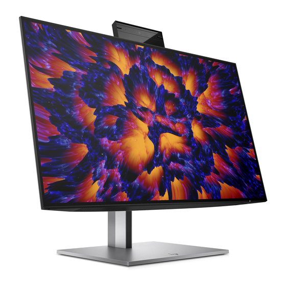
60.5 cm (23.8 in) diagonal viewable screen area with 2560 × 1440 resolution, plus full-screen ● support for lower resolutions; includes custom scaling for maximum image size while preserving original aspect ratio HP Eye Ease with Eyesafe® certification (default mode) to reduce blue light to keep your eyes ● comfortable ●... - Page 7 HP Quick Release 2 device to attach the monitor head to the stand with a click and then remove it ● with the sliding tab release VESA® mounting bracket for attaching the monitor head to a wall-mount device or swing arm ●...
-
Page 8: Front Components
Front components To identify the components on the front of the monitor, use this illustration and table. Table 2-1 Front components, camera model and their descriptions Component Description Tilt levers Allows you to tilt the camera. Camera light On: The camera is in use. Camera RGB lens Transmits your image in a video conference. -
Page 9: Rear And Side Components
RJ-45 port Connects an Ethernet network cable. Green (left): The network is connected. Amber (right): Activity is occurring on the network. NOTE: MAC Address Pass through for HP models only. NOTE: This network port is fully energy efficient according to... - Page 10 the standards of the Energy Efficient Ethernet (IEEE 802.3az- 2010) as long as all connected devices support this feature USB port Connects a USB cable to a peripheral device, such as a keyboard, mouse, or USB hard drive. (10) USB port with battery fast Connects a USB device, provides high-speed data transfer, and charging 1.2 charges small devices such as a smartphone, even when the...
-
Page 11: Locating The Serial Number And Product Number
Locating the serial number and product number The serial number and product number are located on the rear of the monitor. You may need these numbers when contacting HP about the monitor model. For worldwide models (including India): Barcode label & Spec label... -
Page 12: Illustrated Parts Catalog
Illustrated parts catalog To identify the monitor major components, use this illustration and table. Table 3-1: Monitor major components and their descriptions Item Description Part number #ASSY Panel Z24m #Webcam Module Z24m #Audio BD Z24m #ASSY Audio BRKT Z24m #Screw #Screw #ASSY IF BD Z24m #ASSY Driver BD Z24m... -
Page 13: How To Order Parts
#ASSY Power BD Z24m #Screw #ASSY Speaker Z24m #ASSY Webcam Switch BD Z24m How to order parts The HP authorized repair center can purchase the power board from HP. Power board Description HP spare part number Manufacturer part number PWR BD MG238HC-BQCW(C)Z24m G3 BOE N12332-001 755.08102.0001... - Page 14 You can purchase cables from the HP part store at https://partsurfer.hp.com/Search.aspx. NOTE: HP continually improves and changes product parts. For complete and current information about supported parts for your computer, go to http://partsurfer.com, select your country or region, and then follow the on-screen instructions.
-
Page 15: Removal And Replacement Procedures
Removal and replacement procedures Adherence to these procedures and precautions is essential for proper service. Preparation for disassembly Use this information to properly prepare to disassemble and reassemble the monitor. 1) Read the “Important safety information” and “Important service information and precautions” sections in the “Getting started”... - Page 16 2) Remove Rear Cover From Display Head: Use the tool to remove the hinge cover, then release the four screws from back bracket and remove the hinge, then Loose all the hooks by hand for pulling the rear cover...
- Page 17 3) Remove USB board unit from rear cover by unlocking 2pcs screws. Tear off the EMI gasket, then loose the two hooks by hand, and then disconnect the cable...
- Page 18 4) Release OSD key board from rear cover: remove 2pcs screws to release the OSD board, and then remove the OSD key. 5) Disassemble speaker module: remove 4pcs screws and unplug the audio cable from the connector, then remove the two speakers from the holders. 6) Remove Audio board Module: disconnect the seven inside cables from the connectors, then remove 2pcs screws and put it aside.
- Page 19 7) Disassemble Audio Board Module: disconnect the cable, then remove 2pcs screws and release the audio board from the small bracket. 8) Remove the bracket chassis module from the unit: remove 4pcs screws, then disconnect EDP cable away from the connector of panel module. 9) Release bottom bezel assembly by unlocking 6pcs screws.
- Page 20 11) Remove Webcam Module: disconnect panel lamp cable from the connector of the panel, then tear off 1pcs AL foil and 2pcs acetate tape, then unlock 4pcs screws with panel and 3pcs screws with the middle bezel. 12) Disassemble bracket chassis module: Remove 2pcs screws for unlocking the AC power outlet, then remove the Mylar tape from the bracket, and use a screwdriver to remove 9pcs screws, then remove power board, driver board and interface board from main bracket and disconnect all cables.
- Page 21 13) Disassemble Webcam Module: please refer to the following step.
-
Page 22: Power Board
Before removing the power board, follow these steps: Prepare the monitor for disassembly. See Preparation for disassembly on page 12. ▲ Remove the power board: 1) HP Z24m G3 power board connector position is as follows: 2) Locate the part number location on the board. -
Page 23: Connector Repair
3) Pin solder with soldering iron and absorber. 4) Lift the connector up and away from the PCB. Connector repair This procedure includes HDMI, Display Port, Display Port out, USB-C, USB-A and RJ45 connectors. The connectors are on the main board (board part number 7ZB.08101.0009). The connector identifiers are as follows: Connector Location... -
Page 24: Hdmi Connector Hdmi1
Before repairing connectors, follow these steps: Prepare the monitor for disassembly. See Preparation for disassembly on page 12. ▲ HDMI connector HDMI1 Repair the HDMI connector: 1) Use a soldering iron and a de-soldering pump to remove as much solder as possible from the pin. 2) Use a hot air gun to melt the solder on the pins. -
Page 25: Dp Connector Dp1
3) Lift the HDMI connector from the PCB. 4) Place the new component on the PCB. Be sure that it matches the PCB footprint. 5) Solder the new component. DP connector DP1 Repair the DP connector: 1) Use a soldering iron and a de-soldering pump to remove as much solder as possible from the pin. 2) Use a hot air gun to melt the solder on the pins. -
Page 26: Usb-C Connector Usb1
2) Use a hot air gun to melt the solder on the pins. 3) Lift the Mini DP connector from the PCB. 4) Place the new component on the PCB. Be sure that it matches the PCB footprint. 5) Solder the new component. USB-C connector USB1 Repair the USB-C connector: 1) Use a soldering iron and a de-soldering pump to remove as much solder as possible from the pin. -
Page 27: Usb-A Connector Usb2/Usb3
5) Solder the new component. USB-A connector USB2/USB3 Repair the USB-A connector: 1) Use a soldering iron and a de-soldering pump to remove as much solder as possible from the pin. You can gently push down with the soldering iron once everything is molten to move USB-A connector out of the through holes. -
Page 28: Function Test
3) Place the new component on the PCB. Be sure that it matches the PCB footprint. 4) Solder the new component. Function test After repair, be sure to confirm that all functions are working. Table 4-1: Function test Test item Operating description Tool used HDMI test... - Page 29 button has no effect, press and hold the power button for 10 seconds to disable the Power button lockout feature. Master power switch is set to off. Set the master power switch on the rear of the monitor to the On position.
-
Page 30: Index
Index components RC removal, 12 front, 5 rear components, 6 rear, 6 removal connector repair, 20 power board, 19 features, 3 RC, 12 firmware updates, 2 removal and replacement procedures, 12 front components, 5 returning to customer, 2 function test, 25 RoHS (2002/95/EC) requirements, 2 how to order parts, 10 safety information, 1...
Need help?
Do you have a question about the Z24m G3 and is the answer not in the manual?
Questions and answers